CMS Optical Links - Lessons learned from Mass Production J. Troska, S. Dris, K. Gill, R. Grabit, D. Ricci, F. Vasey CERN, 1211 Geneva 23, Switzerland
[email protected]
Abstract The CMS Tracker will install over 40000 optical links in its data-readout and control system, representing an unprecedented deployment of this technology in a Particle Physics Experiment. After reviewing the Quality Process employed in this project, a summary of the performance data measured during production will be shown. The analysis of this data will then be used to illustrate how the performance of the installed system may be predicted, giving confidence that the specified functionality will be attained in the final system. Completion of the production has allowed reflection upon the processes used and improvements for future such projects will be given in the form of some lessons learned.
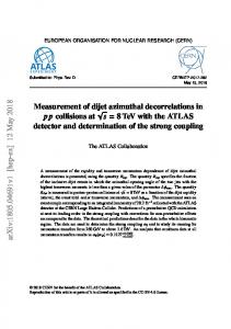
These modules are directly mounted on the 9U Front-End Driver (FED) VME boards that form the CMS Tracker interface to the CMS Data Acquisition (DAQ) system. The Bi-directional Digital Control system re-uses the same fibre plant as the Readout system described above. Control data generated on the Front-End Controller (FEC) 9U VME board in the Counting room. These data are converted to optical by the transmitter side of a bi-directional 4-channel optical Transceiver (DTRx). They are received by individually pigtailed photodiodes and interpreted by the Rx40 receiver ASIC mounted on Digtial Optohybrids distributed throughout the Tracker volume. After passing around the electrical control ring the signals are re-transmitted to the Receiver part of the DTRx on the FEC by the analogue laser transmitter and driver that are re-used in a digital fashion.
I. INTRODUCTION The CMS Tracker[1] is currently in the final stages of assembly of its sub-structures in preparation for installation within CMS as a whole in time for first collisions at the LHC in 2007. The readout and control system of the Tracker uses optical data transmission with a channel density unparalleled anywhere – 40000 analogue readout channels are combined with 3000 digital control channels. Once the success of the design of the Tracker systems was proven in system tests the optical components on which it is based were adopted for use by other Sub-detectors of CMS. With the addition of readout and control systems for ECAL, Preshower, RPC and Totem the total quantities increased by an additional 22000 fibre channels that re-use the Tracker components for Digital transmission systems. This scale of production of components has not been seen before in particle physics and with the production now complete it is timely to sum-up the project and reflect upon the lessons learned so that they may serve future projects of this scale and/or nature. The CMS Tracker Optical Readout and Controls systems[2] are shown schematically in Figure 1. The readout system consists of laser transmitters coupled to a Linear Laser Driver (LLD) on the Analogue Optohybrid that is connected to the Silicon Microstrip Detector Modules distributed throughout the Detector Volume. The lasers are individually pigtailed with MU connectors that allow for the highest connection density available from a standardised optical connector at the first patch panel that is also distributed across the detector volume at the edges of the various mechanical support structures of the tracker. At this distributed patch panel the individual lasers connect to optical fan-outs that bring the fibres into 12-fibre ribbon cables. These cables connect via MFS-type connectors to high-density rugged multi-ribbon cables at the In-line Patch Panel located inside the CMS cryostat just beyond the level of the ECAL. The Multi-ribbon cables containing a vertical stack of 8 ribbons span the 40-65m to the shielded counting room where each ribbon connects to an Analogue Receiver (ARx) Module. 529
Figure 1: Showing the CMS Tracker Optical Readout and Control Systems.
It is also important to note that there are a few peculiarities that distinguish how a particle physics collaboration (albeit represented by CERN) is constrained in its dealings with industrial partners responsible for turning designs into reality on a large scale. The first important constraint to note is that the timescales from first discussion of feasibility with a manufacturer to the placing of a large-volume order and then completion of production is measured in significant multiples of years. This may prove to be difficult for industrial partners to manage, especially in the fast-moving high-technology area. To mitigate this it is imperative to build a good, strong, relationship with the manufacturer from the start – this will also become important when overcoming the inevitable problems when they occur during production.
Prototyping Prototype Validation Publications
Pre-production
Market Survey
Purge & Test by Manufacturer
Sample Validation Invitation to Tender
Qualification
Advance Rad-Hardness Validation
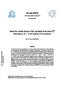
Performance in terms of uniformity of measured parameters remained excellent throughout production, as shown in Figure 4 and Figure 5. Values measured during production remained centred within the specification window. 0 0.06
0.04
Assembly
Figure 2: Showing the Project Quality Process, moving from Prototyping via Pre-Production and Production to Assembly.
0.03
0.032W/A
0.03
0.02
0.019W/A
0.02
0.01
0.013W/A
0.01 0
Apr 04 Jan 05 Oct 05 Delivery Date
Figure 4: Showing the production trend (left) in terms of minimum, (inverted triangles) maximum (triangles and mean (circles) values of the laser slope efficiency over time for all delivered batches. The corresponding histogram for all delivered lasers is shown on the right. The specification is shown for both readout (top family) and control (bottom family) lasers 0
100 Laser Threshold Current (mA)
40 20
12
12 10mA
10
Jan 03
Jan 04 Jan 05 Delivery Date
Jan 06
Jan 07
Figure 3: Showing the delivery of components over time. Each symbol represents a delivery that required QC testing at CERN.
Figure 3 shows all deliveries of all components over time. Since each marker also represents a Quality Control (QC) test carried out at CERN, the QC workload can be seen to be nonnegligible during the entire 4-year production period.
III. PRODUCTION DATA A. Laser Diodes The contract for supply of laser diodes was awarded to ST Microelectronics of Milan, Italy, in 2002 for a total quantity of 45000 for the CMS Tracker Readout and Control systems. The same component was then also re-used by the ECAL readout and the ECAL and RPC control systems, leading to an 530
10
8
8
6
6
4
4 Jan 03
0
Count 5000 10000
Jan 04 Jan 05 Delivery Date
Laser Threshold Current (mA)
Pigtail Laser ARx Harness Fanout Cable PIN DTRx
0.05 0.04
Jul 03
Full test
Percentage of Total Quantity
0.048W/A
0
Lot validation
60
0.06
0.05
Production Purge & Test by Manufacturer
80
Count 5000 10000
Laser Slope Efficiency (W/A)
The Quality Plan [3] put in place in order to ensure the required quality during mass production of optical link components led to the flow of actions shown in Figure 2. The project was divided into four distinct phases, starting with Prototyping and ending with the Assembly of the components into the structures of the CMS Tracker. Industrial partners were vital to provide the production capacity needed for the large number of components in the system. For this reason all components are COTS or COTS-based with minimal modifications. Testing of the key performance parameters was carried out by the manufacturers at the 100% level, with the measured data being made available to CERN. Validation was then carried out at CERN by measurement of a similar parameter set on a per-batch sampling-basis to maintain confidence in the manufacturing data.
increase in total quantity to over 65000 lasers. After some initial difficulties for the manufacturer to ramp-up production due to staff training issues and vacations, the target rate of 3000/month was achieved and maintained for over one year. Lasers were assembled from COTS laser die manufactured by Mitsubishi Electric of Japan and Terminated Fibre Pigtails manufactured by Sumitomo Electric of Japan.
Laser Slope Efficiency (W/A)
II. QUALITY PROCESS
Jan 06
Figure 5: Showing the production trend and histogram for the threshold current of the laser diodes. All lasers have room temperature threshold currents below the specified 10mA.
B. Analogue Receiver Modules The CMS Tracker Readout system requires a total of 4500 analogue receiver modules (ARx12). NGK Ltd of Japan delivered the intitial quantity of 85% in the first 6 production batches up to July 2004 and subsequently had to wait for almost a full year before the order confirmation was granted by the Tracker for the full quantity. This explains the first gap in Figure 6 and Figure 7. A final purchase was made for spares in 2006 before the supplier closed their optoelectronics manufacturing facility. This component is the only one to have passed the qualification testing in the first pass, a testament to the high production quality achieved.
Count 2000 4000
48
48
44
42 A/W
44 40
36
36
32
32
28
28 27 A/W
24 20
24 20
Jul 03
Apr 04 Jan 05 Oct 05 Delivery Date
Figure 8 shows that the high performance of the singlefibre sMU was achieved throughout the production. Figure 9 shows the same for the ribbon connectors mounted on rugged fanouts. The low losses achieved are in marked contrast to the expectation that the distribution would be a rectangle within the specification window. 0
Figure 6: The production trend and histogram for the responsivity of 12-channel Analogue Receiver Modules show all channels of all modules to be have min. 27 and max. 42 A/W responsivity.
140
160 140
120
120
Typ. 100MHz
80
100 80
Jul 03
Apr 04 Jan 05 Oct 05 Delivery Date
Figure 7: The production trend and histogram for the bandwidth of 12-channel Analogue Receiver Modules show that the typical spec of 100MHz is comfortably met.
C. Rugged Fanouts Single-fibre connectors are used in the CMS Tracker to connect the highly distributed transmitters and receivers of both the control and readout systems to high-density 12-fibre ribbons. The connector type chosen by CMS for this task is the industry-standard MU, which provides the highest stacking density of any standard connector. This high density is required due to space constraints inside the Tracker. The optical fibre (SMF-28 from Corning USA) was ribbonised and made into a rugged cable by Ericsson of Sweden. Production of the sMU-MFS (single-fibre to multi-fibre ribbon) fanouts proceeded in two steps: in the first Sumitomo of Japan produced symmetric harnesses with individual fibres broken-out of the ruggedised ribbon at both ends and connectorised with sMU connectors; this assembly was then cut by Diamond of Switzerland who terminated the ribbon directly with the chosen ribbon connector (MFS). Both manufacturers required some ramp-up time for their production process to reach the specified performance. Once this stage was overcome both manufacturers were able to sustain a high production rate over approximately one year. The last deliveries were delayed by the need to reach a 531
0.6dB
0.6
0.6
0.4
0.4
0.2
0.2 0.0 May 04
Jan 05 Sep 05 Delivery Date
Figure 8: The production trend and histogram of the single-fibre connectors (sMU) on rugged fanouts shows that the insertion loss spec. of 0.6dB is comfortably met. 0
Count 5000
2.0
10000 2.0
1.6
1.6 1.2dB
1.2
1.2
0.8
0.8
0.4
0.4
0.0 Jan 04
MFS Insertion Loss (dB)
100
Module Bandwidth (MHz)
Module Bandwidth (MHz)
Count 2000 4000
0.8
0.0
MFS Insertion Loss (dB)
0
160
Count 5000
0.8
sMU Insertion Loss(dB)
40
Module Responsivity (A/W)
Module Responsivity (A/W)
0
consensus within the user community for final needs and funding.
sMU Insertion Loss(dB)
Figure 6 and Figure 7 show that the production is well centred within the specification window for the gain (Figure 6), and in excess of the typical specification on bandwidth (Figure 7).
0.0 Sep 04 May 05 Jan 06 Delivery Date
Figure 9: The production trend and histogram of the 12-fibre ribbon connectors (MFS) on rugged fanouts, showing the improvement in insertion loss achieved as production proceeded, always staying within the spec. of 1.2dB maximum.
D. Multi-Ribbon Cable Rugged high-density multi-ribbon cables carry the signals over the longest span in the CMS Tracker Readout and Control links. These cables were the last items to be produced due to the long time required to obtain accurate lengths for these cables. Lengths must be known before cable production since the termination must be carried out in a controlled manufacturing environment. As for the Fanouts, the optical fibre used is SMF-28 from Corning USA that was ribbonised and made into a rugged 8-ribbon cable by Ericsson of Sweden. Performance of ribbon connectors is generally worse in terms of insertion loss than that of single-fibre connectors due to the difficulty in achieving geometrical alignment between multiple fibres simultaneously. Insertion loss of the connectors manufactured by Diamond of Switzerland (shown in Figure 10 and Figure 11) was uniformly good throughout
production for the connectors at both ends of the cable (MFS at front-end & MPO at back end).
800
1.2dB
-1.2 -0.8
-1.2 -0.8
-0.4
-0.4
400 200 0 0.60
1.10
-1.2
-0.8
-0.8
-0.4
-0.4
MPO Insertion Loss (dB)
1.2dB
0.0 May 05 Nov 05 May 06 Delivery Date
Figure 11: The production trend and histogram of the MPO ribbon connectors on the multi-ribbon cable – all below max. of 1.2dB.
E. Photodiodes Once development of the digital control system of the CMS Tracker had been completed, several other sub-detectors in CMS decided to use it (ECAL, RPC & TOTEM). This led to an overall doubling of the required number of digital control links and thus of components. This change was known before the production of photodiodes had ramped-up and the bulk of the production could occur at once. The last quantities of spares and late additions were delivered in mid-2005. Production uniformity was good, with Fermionics of California, USA, taking sufficient margin for device responsivity w.r.t. the specification - as shown in Figure 12. Other parameters showed a similarly good overall performance which gives confidence that the digital link will operate with sufficient margin.
The digital transceiver (DTRx4) is the only part in the entire system that was a pure COTS part from NGK of Japan. This module was designed for digital operation at 2.5Gb/s per channel, which would yield a bi-directional 10Gb/s link with 4+4 (Tx+Rx) channels between modules. The first task of qualification was thus to ensure that the modules would operate at the CMS Tracker Control System data rate of 80MB/s. Production of DTRX4 started before funding was fully available for the parts of CMS that were late to make use of the Tracker Control System, which led to a distinct step in the production with a 6-month gap. Finally, funding for spares was long in being made available and came just in time for the last buy notice that preceeded the closure of the manufacturing facility. Once again the manufacturer's production measurements (Figure 13) show that production met the specified performance targets. The Optical Modulation Amplitude is the size of the signal produced by the Transmitter portion of the DTRx. 120 100 80 60 40 20 0 -20
-16 -12 -8 -4 Average DTRx Module OMA (dBm)
Max. -3dBm
-1.6
Min. -12dBm
Count 5000 10000
F. Digital Transceiver Modules
Count
0
-1.2
0.70 0.80 0.90 1.00 Photodiode Responsivity (A/W)
Figure 12: Showing the histogram of Photodiode Responsivity for all delivered components.
-1.6 MPO Insertion Loss (dB)
600
0.0 May 05 Nov 05 May 06 Delivery Date
Figure 10: The production trend and histogram of the MFS ribbon connectors on the multi-ribbon cable – all below max. of 1.2dB.
0.0 Nov 04
Count
-1.6 MPO Insertion Loss (dB)
MFS Insertion Loss (dB)
-1.6
0.0 Nov 04
1000
Count 5000 10000
Min. 0.75A/W
0
1200
0
Figure 13: Showing the histogram of the average Optical Modulation Amplitude (OMA) for all delivered DTRx modules.
IV. VERIFICATION OF FULL SYSTEM FUNCTIONALITY In the analogue readout system of the CMS Tracker the gain is a critical parameter. The overall gain is the product of the gains of all of the components in the chain, as represented schematically in Figure 14. 532
sufficiently detailed level to overcome the inevitable problems related to the ramp-up of production. Figure 14: Schematic view of optical readout chain.
Since we have access to the production data (that includes the gain of each component) we can simulate the statistical gain distribution of all links that will be installed [4]. For the case where all gains are combined and no tuning is carried out we achieve the solid line histogram shown in Figure 15 that is centred on the target typical gain of 0.8V/V. As shown in [4], we can tighten the final “in-use” spread to only ± 20% so that the final distribution is bounded by the dot-dash lines of Figure 15.
Count
Typ. 0.8V/V
Un-switched case
0.8 Analogue Readout Link Gain (V/V)
Ramping up of production took longer than predicted in all cases. This was due to a number of things, including optimism about the complexity of producing custom parts and poor quality of initially delivered components. The timescales on which problems were solved was measured in months, due to the complexity of the processes & components and the need to understand the root causes of problems. The funding profiles available to large particle physics experiments appear to leave large gaps in procurements as decisions to fund additional parts and/or spares take time. Where the manufacturer is dealing with a relatively standard product, such as connectors, this only poses a problem of fitting the new requirements into their production plan. However, where the components are customized the knowledge of how to produce them may go stale, leading to poorer performance of components produced later.
Spread with Gain Switching Achieve 0.8±0.16 V/V
0.0
The procedures used to qualify and accept production components must be in place before production starts for discussion with the manufacturer. Failure to do this leads to delays as the discussion on how to do testing is re-opened when a component fails a test.
Overall, production of components took 4 years to complete and, barring problems in start-up and re-starting, went very smoothly thanks to good preparation.
1.6
Figure 15: Gain distribution of analogue readout links based on production data of components, showing that a tight tolerance around the target typical gain of 0.8V/V will be achieved.
Having access to the detailed performance measurements has been invaluable to implementing a fully functional analogue readout system. The high delivered performance of all components, especially the optical connectors, would have caused the final installed links to have too high a gain and thus a reduced dynamic range had it not been for the fact that it could be detected early enough to act. By reducing the size of the load resistor at the end of the chain it has been possible to produce a system that will meet the overall dynamic range requirement by re-centring the histogram in Figure 15 on the target gain of 0.8V/V.
VI. SUMMARY & CONCLUSIONS Component production for the CMS Tracker optical links is now complete, a process that has taken 4 years overall – not including the time needed for contract negotiation and placement. This seemingly lengthy time period was necessary to ensure the high quality of all produced parts. It has proven to be invaluable to have traceability of component performance through production testing carried out at the 100% level. This has allowed us to verify the proper functioning of all links (assemblies of components) built.
ACKNOWLEDGEMENTS
This would not have been possible without the detailed production measurements carried out by all the manufacturers. System testing using samples from production also allowed the scaling of gains measured during production at room temperature to the low (-10C) operating temperature of the final installed system.
The excellent overall production quality reported here would not have been possible without the diligent and professional attitude shown by all manufacturers mentioned in the text, an effort for which we gratefully acknowledge their contribution.
Using the production measurements of digital link components it is also possible to predict the margin of operation of the installed digital control system. By comparing the signal output of the DTRx module with the minimum allowed signal size (sensitivity) of the front-end receiver with which it must operate we calculate a system margin of 6.8dB including connectors. The digital control system thus has a comfortable margin of operation.
[1[ CMS Tracker Technical Design Report and Addendum, CERN/LHCC 98-6 and CERN/LHCC 200-016
V. LESSONS LEARNED For a large-scale production such as this it is imperative to have detailed specifications, derived from user requirements, in order to have fruitful discussions with manufacturers at a 533
REFERENCES
[2] J.Troska et al., “Optical Readout and Control Systems for the CMS Tracker”, IEEE Trans. Nucl. Sci., Vol.50, No.4, pp.1067-1072 [3] CMS Tracker Quality Plan, EDMS Document Number: CMS-TK-MA-0001 v.1.2 [4] S.Dris et al., “Predicting the In-System Performance of the CMS Tracker Analog Readout Optical Links”, Proc. LECC 2004