component-based software system for business reporting. ... not know how their components will be assembled, deployed, or used to ensure broad .... a component depends on the failure probability of the hardware nodes it is allocated on.
Life-Cycle Aware Modelling of Software Components Heiko Koziolek1 , Steffen Becker2 , Jens Happe1 , Ralf Reussner1 1
Chair for Software Design and Quality? Am Fasanengarten 5, University of Karlsruhe (TH), 76131 Karlsruhe, Germany 2 FZI Forschungszentrum Informatik Haid-und-Neu-Straße 10-14, 76131 Karlsruhe, Germany {koziolek,sbecker,happe,reussner}@ipd.uka.de
Abstract. Current software component models insufficiently reflect the different stages of component life-cycle, which involves design, implementation, deployment, and runtime. Therefore, reasoning techniques for component-based models (e.g., protocol checking, QoS predictions, etc.) are often limited to a particular life-cycle stage. We propose modelling software components in different design stages, after implemenatation, and during deployment. We allow the composition of models of different development stages. Thus, abstract models for newly designed components can be combined with refined models for already implemented components. Furthermore, we propose explicit modelling of a component’s context, which influences extra-functional properties, but should stay separated from component specifications. As a proof-of-concept, we have implemented the new modelling techniques as part of our Palladio Component Model (PCM). In this paper, we show how these techniques improve analysing a component-based software system for business reporting.
1
Introduction
Methods for model-based reasoning about component-based software architectures shall enable software architects to assess functional properties (e.g., correctness, interoperability, etc.) and extra-functional (e.g., performance, reliability, etc.) properties already during design [24]. By composing individual component specifications and running different analysis and simulation tools, the properties of the whole system shall be evaluated based on the properties of its individual parts. These methods shall avoid the implementation of designs, which exhibit insufficient functional or extra-functional properties. During component-based system design, software architects specify new components and incorporate existing components in their architectures [5]. To support this mixed (i.e., top-down and bottom-up) development process, modelling and analysis methods must account for different stages in the component life-cycle. A step-wise refinement of component specifications is desirable as components progress from the design to implementation stage. To enable the prediction of extra-functional properties, the software architect needs additional information about a component regarding ?
This work is supported by the German Research Foundation (DFG), grant GRK 1076/1
its assembly, deployment, and usage, which can already be modelled during early development stages. This contextual information about a component cannot be supplied by component developers as part of a component specification, because they should not know how their components will be assembled, deployed, or used to ensure broad reuse. Existing models for component-based systems support different stages in the component life-cycle only insufficiently [12]. Industrial component models, such as EJB [7], COM [6], or CCM [17], only refer to component implementations, but not to component designs. Furthermore, their support for functional and extra-functional analysis is limited. Other component models (e.g., SOFA [19], ROBOCOP [4]) mix up component specifications and contextual information in a single model that does not account for the different developer roles supplying this information (e.g., software architect, component developer). This approach requires to change the component specifications manually, if the components are composed into a specific context. We propose modelling software components during different design stages and allow combining coarse specifications of new components with refined specifications of already implemented components to improve functional and extra-functional analysis. If the development of a component-based system progresses, coarse models of individual components can be refined with additional information thereby increasing the accuracy of analysis methods. Furthermore, we propose modelling contextual information of software components in separated context models aligned with different developer roles participating in the development process (i.e., software architect, system deployer, and domain expert). Our model allows to automatically adapt parametrised specifications of individual software components (supplied by component developers) to these third-party defined context models to correctly reflect the functional and extra-functional properties of a software component in a specific deployment context. Thus, the component specification by the component developer stays free from any contextual information. Our approach improves functional and extra-functional reasoning for componentbased software architectures, as it better reflects the different life-cycle stages of a software component than existing approaches. It allows a division of the modelling effort to different developer roles, who can work independently and focus on their specific viewpoint of the system. Component specifications by component developers including extra-functional properties are completely reusable with our approach as they are not tied to a specific context. They can be stored in repositories, so that different software architects can include them into their models. The contributions of this paper are (i) a component type hierarchy that enables modelling software components at different design stages, and (ii) an explicit context model for software components that enables different developer roles to add information necessary for analysis without altering component specifications. We meta-modelled both concepts and added them to our Palladio Component Model (PCM) [3]. To illustrate the benefits of our approach, we model the components of a business reporting system during different stages of their life-cycle in this paper.
This paper is organised as follows. Section 2 introduces the running example of a business reporting system, which motivates the need for the new modelling concepts. Section 3 introduces our concepts for modelling software component during different development stages. Section 3.1 sketches the development process targeted by our method and the involved developer roles. Afterwards, Section 3.2 introduces the PCM type hierarchy, before Section 3.3 presents the PCM context model consisting of specifiable and computable parts. Section 3.4 briefly explains the possibilities for analyses based on the model. Section 4 compares our approach with related work, before Section 5 concludes the paper.
2
Running Example
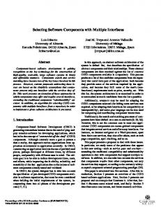
To illustrate the new concepts introduced in this paper, we will use the so-called ”Business Reporting System” (Fig. 1) as a running example. It is a typical 4-tier architecture including a web server, load balancer, multiple application servers, and a database server, and is loosely based on an industrial case study. Webserver WebForm1
WebForm2
Monitoring
WebForm3
resourceDemand= 100 CPU Units
LoadBalancer Dispatcher
Internal Computation
AppServer1 Business Reporting
probability=0.1
AppServer2 Monitoring
Business Reporting
Report2
probability=0.9
Monitoring
Report2
Required ServiceCall Report1
Required Service Call
Report1 Cache
Cache
Cache
Cache
iterations=3
DatabaseServer DatabaseComponent
Fig. 1. Example Model of a Component-based Software Architecture
The Business Reporting System manages the business data of a company. It supports monitoring the current status as well as generating condensed reports for larger periods of time. The architecture includes replication and caching for increased performance and reliability. Although being a simple example, the Business Reporting System includes multiple instances of some components at different locations. Thus, these component instances reside in different contexts. As functional and extra-functional analysis depends on the context of a component, but component developers should not know the context their
components will be deployed in, contextual information has to be supplied by other developer roles. The design comprises a replicated application server. Both application servers contain the same components, but each server hosts its own instances. A single QoS specification for the component is therefore not sufficient to model the actual performance or reliability of the component instances. The application servers run on different hardware, which influences the performance and reliability properties of the components. Therefore, the component QoS specification by the component developer needs to be adaptable to different deployment environments. For example, the failure probability of a component depends on the failure probability of the hardware nodes it is allocated on. Besides different allocations of the same component to different hardware nodes, components can be composed multiple times in the same architecture. Software architects can compose them with other components (i.e., horizontal composition) or nest them into composite components (i.e., vertical composition). Consider the component Cache on application server 1, which is on the one hand horizontally composed with the component Monitoring and on the other hand vertically composed into the component BusinessReporting. According to their compositions, these components may behave differently. For example, the response time perceived at the component’s provided services depends on the execution times of the connected required services. Clients can also use the same component differently in a single architecture. The term ”use” subsumes the number of users or other components concurrently requesting service, parameter values they use, and the propagation of requests to other components via required interfaces. Usage may alter a components extra-functional properties. For example, the run time of a component service sorting arrays depends on the size of the arrays provided as parameter values. Furthermore, depending on input parameter values, a component may propagate a different number of requests to other components, which can lead to increased network traffic. Propagation of requests cannot be determined using only black-box specifications. Therefore, several component-based prediction approaches use an abstract behavioural specification for component services [1], which describes the sequence of using required services and the use of hardware resources. This enables specifying the propagation of user requests. Fig. 1 contains an example of such a behavioural abstraction for the Monitoring component on the right hand side. The depicted control flow graph subsumes all internal computations by the component in a single activity (”internal computation”) and calls required services explicitly (”required service call”). The branch transition probabilities, loop iteration numbers, and resource demands are needed for QoS prediction, but depend on how the component service is used by its clients. Thus, they cannot be specified by the component developer as they may change depending on the usage of the component. For example, the abstract behavioural specification of the Monitoring component instance on application server 1 possibly has different branch probabilities, because the Dispatcher component may direct computational intense requests to this server.
Most component models do not reflect the context (i.e., assembly, deployment, and usage) of a component explicitly, but instead rely on fixed specifications. However, contextual information cannot be contributed by the component developer, as it should remain open how the component is assembled, allocated, and used to assure broad reuse. This paper demonstrate how the contextual influences of a componet’s performance can be parameterised. Each role involved in the component based development process provides its part of the information. Model transformations combine the specifications to evaluate the performance and reliability of a component-based software architecture in a given context.
3
Meta-Modelling Components during Life-Cycle
This section first sketches the component-based development process with the involved developer roles (Section 3.1). Afterwards, it introduces new concepts for modelling software components during design (Section 3.2) and deployment (Section 3.3). Finally, this section describes techniques for functional and extra-functional analysis based on the newly introduced models (Section 3.4). 3.1
Component-based Development Process
The component-based development process involves several developer roles with specific responsibilities. The following roles are particularly relevant in our setting [11]: – Component Developers specify and implement software components either from scratch or using existing components. They develop components for a market as well as per request. They make as few as possible assumptions about a specific deployment environment to ensure broad reuse. – Software Architects lead the development process for a component-based application. They design the software architecture and delegate tasks to other involved roles. For the design, they decompose the planned application’s specification into single component specifications. – System Deployers set up the hardware and middleware resources the components shall be allocated on. They determine which resources are needed, and how the components shall be distributed among them. – Domain Experts participate in the requirements analysis, since they have special knowledge of the application’s business domain. They analyse the anticipated behaviour of the users interacting with the application. – QoS Experts collect QoS-relevant information from the different developer roles and assess the extra-functional properties of the system. In practice, the process has to consider the desired reuse of components as well as new requirements. Software architects can use existing components from repositories or specify new ones for specific requirements, which shall be implemented by component developers. During the specification of a software architecture, some of the used
components are already specified and implemented while others are only sketched. As a consequence, the component-based development process does not follow a strict separation into classical top-down (i.e., going from requirements to implementation) and bottom-up (i.e., assembling existing component to create an application) categories. Instead, it is a mixture of both approaches. Any software component model should account for the different developer roles and the mixed top-down and bottom-up development process. Supporting different developer roles is beneficial as it allows reducing the complexity of modelling, because the roles only need to provide information about their restricted viewpoint of the whole system and can work independently. Supporting the mixed development process is beneficial as it allows software architects to reason about the properties of their architecture during early development stages when some components are not implemented yet, but at the same time allows to rely on refined models of already implemented (e.g., thirdparty) components. However, at this stage it is less costly to change design decisions. 3.2
Component Design
Complete Provides Type Type ImplementationType
Component Type
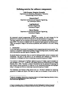
To support model-based reasoning about component-based designs in a mixed topdown and bottom-up development process, it is necessary to model components in different development stages. It must be possible to successively refine components from early development stages. There are at least three different stages of component specification as depicted in Fig. 2 and described in the following from top to bottom.
Recommendatory Recommendatory Required Interfaces Required Interfaces
IBusinessReport
n
(may be used, but others may be used as well)
m n
IBusinessReport
Restricting Restricting Required Interfaces Required Interfaces
IDB
(only (only the the specified specified interfaces interfaces may may be be used) used)
BusinessReporting
m
IDB
Report1
IBusinessReport
Compulsory Required Interfaces (must be used in a certain way, e.g. according to protocol)
Report2
Cache
Fig. 2. Component specification in different development stages
1. Bundling Provided Services into Components: At the first stage, software architects specify components based on their desired functionality using provided interfaces. The architects might be unsure, which other components are required to provide this functionality, but nevertheless they want to include the desired functionality in
their model for early reasoning. Fig. 2 contains the BusinessReporting component from Fig. 1 as an example. We call such component specifications, which include provided interfaces, but only optionally include required interfaces provides component types. These components are merely stubs for reasoning and can for example contain estimated QoS-annotations (e.g., execution times, failure probabilities) for early QoS predictions. 2. Full Specification of Required Services: At the second stage, it becomes clear to the software architect, which components are additionally required to provide a certain functionality. In this stage, the implementation of the component is still unknown and there are multiple possibilities to realise a component conforming to the specified interfaces. For example, component developers can use different algorithms and data structures behind the same interfaces. The specified required interfaces in this stage can (but need not) be used by component developers implementing the component. However, they may not use additional required interfaces to remain type-conform. We call such component specifications, which include provided interfaces and required interfaces, complete component types, as all their interfaces are known. Software architects can pass these component specifications to component developers as requirements specifications. A complete component conforms to a provided component (and thus can substitute it), if and only if it provides at least the services specified in the provided type. With complete component type, functional and extra-functional analysis can be refined, as for example estimated QoS-annotations can now also refer to required services. 3. Modelling Component Implementations: At the third stage, a component specification has been implemented, and a model of the implementation (with refined information) should be included in the architectural design model to improve the accuracy of analyses. Developers can either assemble other components to implement a component (i.e., a so-called composite component) or directly implement them (i.e., a socalled basic component). The models of these component implementations can be refined with service effect specifications (SEFF), which are a high-level abstractions of the behaviour of component services and model how provided services of a component call the required interfaces. SEFFs are useful for many kinds of functional and extra-functional analysis (e.g., protocol checking [20], reliability prediction [22], performance prediction [2], testability [23]). A basic or composite component impl-conforms to a complete type (and thus can substitute it) if and only if it provides at least the services specified in the provided interfaces of the complete type and it requires at most the services specified in its the required interfaces of the complete type. This principle is known as contra variance [24]. The conforms as well as the impl-conforms are n:m relations. Each basic or composite component can conform to multiple complete types and each complete type can be implemented multiple times. Realisation: Fig. 3 shows the realisation of the formerly described component type hierarchy in the PCM meta-model. Abstract meta-classes are colored in light grey. We have introduced an explicit abstract class for the concept of providing and requiring an interface, as it is common for all types of components.
ProvidedRole
*
*
Interface
*
RequiredRole *
InterfaceProvidingEntity
InterfaceProvidingRequiringEntity
InterfaceRequiringEntity
ProvidesComponentType * * CompleteComponentType
ServiceEffect Specification *
* * ImplementationComponentType
BasicComponent
CompositeComponent
Fig. 3. PCM Component Type Hierarchy (Meta-Model)
PCM Interfaces mostly follow the syntax and semantics of CORBA IDL [17], therefore we omit the full meta-model for interfaces for clarity. PCM Interfaces are first-class entities and may exist independently from components. The specification of a RequiredRole to an Interfaces has different semantics according to the underlying component type (i.e., recommended, restricted, or compulsory as described above). Meta-classes for QoS annotations (e.g., for provides and complete component type) have been omitted for brevity. Component developers specify QoS properties of BasicComponents using ServiceEffectSpecifications. Their meta-model is extensively described in [3]. Tools can compute the QoS properties of CompositeComponents by combining the ServiceEffectSpecifications of the included BasicComponents. 3.3
Component Deployment
While component developers supply individual component specifications, further information about each component in an architecture is necessary to enable analyses. This information refers to the component context. It is only available when the component is composed into a specific architecture and thus cannot be supplied by the component developer. A context model necessary for reasoning about component-based designs consists of elements that have to be specified manually, and parts that can be computed. Tab. 1 depicts different elements of such a model. The following describes them in detail. The assembly context refers to a component’s binding to other components and nesting inside components. The manually specifiable part includes both the connections to other components via provided and required interfaces and the containment relationship between vertically composed components. The computable part refers to the parametric contracts introduced by Reussner [21]. For example, parametric contracts allow to restrict the set of required services of a component if provided services using them are not needed in a particular context.
Assembly Context
Allocation Context
Specified by Software Architect: • Horizontal Composition: Binding to other Components • Vertical Composition: Encapsulation in Composite Components
Computed by Tools: • Parametric Contracts o Provided/Required Services o Provided/Required Protocols o …
Specified by System Deployer: • Allocation to Hardware Resources • Configuration o Component, Container o Communication o Security, Concurrency o … Computed by Tools: • Allocation-dependent QoS Characteristics o Timing Values for Resource Demands o Failure Probabilities o …
Usage Context Specified by Domain Expert: • Usage at System Boundaries o User Arrival Rate o Number of Users o Request Probabilities o Parameter Values
Computed by Tools: • Usage inside Components o Branch Probabilities o Loop Iteration Numbers o Input/Output Parameters o Usage-dependent Resource Demands
Table 1. Component Context Model
A basic or composite component type can have multiple assembly contexts in the same architecture model. In this case, each assembly context refers to a copy of the same component implementation. In the architectural model from Fig. 1, the component type Cache would be referenced by four different assembly contexts, as there are four different instances of the component in the architecture, but type Cache itself only exists once. The allocation context refers to a component’s binding to hardware/software resources. It requires manual specification of a component’s allocation and configuration options related to hardware and software resources. Tools can compute allocationdependent QoS characteristics of a component by combining information from the component specification and the hardware environment. For example, a resource demand provided by a component developer (e.g., 500 CPU Units) can be transformed into a timing value (e.g., 0.25 seconds), if the speed of the underlying hardware resource is known (e.g., 2000 CPU Units/seconds). A basic or composite component type can have multiple allocation contexts in the same architecture, in which case each allocation context refers to a copy of the same component implementation running on different resources. As an example, the component type BusinessReporting from Fig. 1 resides in two different allocation contexts, as it is allocated once on application server 1 and once on application server 2. The usage context refers to the number of clients using a component, their sequence of calling provided services, and the input parameter values they use. Domain experts only need to specify this information at the system boundaries, tools can then propagate it through the component-based architectural model using SEFFs. Section 3.4 will detail on this. As an example, the Monitoring component instances from Fig. 1 may be used differently (i.e., reside in different usage contexts), because the Dispatcher may direct different kinds of requests to each instance.
Specified by Domain Expert
CompositeComponent
System 1
* Specified by Software Architect
ComposedStructure
1
*
1
*
Allocation
* InterfaceProviding RequiringEntity
1
*
1
ProvidedRole
+providedRole
1
*
*
1
*
1
UsageModel
ResourceEnvironment
*
AssemblyContext +providingChild
1
AllocationContext
* ResourceContainer
1 +requiringChild
AssemblyConnector
+requiredRole
1
RequiredRole
Specified by System Deployer
Fig. 4. PCM Context Model, Specifiable Parts (Meta-Model)
Realisation: Fig. 4 shows the realisation of the manually specifiable parts of the context model in the PCM. It should be understood as a first initial implementation of the context concept, which can be extended in the future. The software architect composes components using AssemblyContexts, which reference a particular component type. Each AssemblyContext models a single instance of a the component type. AssemblyConnectors bind components together as they reference two AssemblyContexts and the ProvidedRole and RequiredRole of the encapsulated components. Composed AssemblyContexts form a ComposedStructure, which can either be a CompositeComponent ready for further composition, or a System, which is the top-most composite structure of an architectural model (i.e., it cannot be encapsulated into another ComposedStructure). System deployers model the ResourceEnvironment that contains a number of ResourceContainers (e.g., servers), which in turn may contain different hardware resources (e.g., CPU, HDs, not depicted here). The deployers allocate AssemblyContexts (i.e., composed component instances) to ResourceContainers using AllocationContexts. Domain experts model the number and type of user requests at the system boundaries. In the PCM, they specify this information in the so-called UsageModel, which references the System. It allows specifying the sequence of user requests to components at the system boundaries (e.g., the WebForm components in Fig. 1), as well as parameter values. The full PCM usage model is described in [3]. The following section describes the propagation of values specified in the UsageModel to individual AssemblyContexts. 3.4
Computed Context Models and Analysis
Tools can compute information for functional and extra-functional analysis out of the specifications provided by the different developer roles in the formerly described manually specified context model. This information depends on a component instance’s
assembly context, allocation context, and usage context. As the domain expert has specified the usage at the system boundaries, component developers have specified SEFFs, and the software architect has specified the component assembly, parameter values from the usage model can be propagated through the architecture. With the allocation contexts provided by the system deployer, the execution times for component services can be computed out of the parametrised resource demands specified by the component developers.
1
Computed by Tools
+actually ProvidedRole
*
AllocationContext
1
* ComputedAssemblyContext *
1
AssemblyContext
1
* ComputedUsageContext
1
*
ComputedAllocationContext
*
+actually RequiredRole
* BranchProbability branchProbability:Double
* LoopIteration
* Input
*
* Output
ResourceDemand
*
* * ProvidedRole
* RequiredRole
1 AbstractBranch Transition
1 Abstract LoopAction
1
1
RandomVariable
1 Parametric ResourceDemand
Fig. 5. PCM Context Model, Computable Parts (Meta-Model)
The PCM supports three different types of computed contexts as depicted in Fig. 5, which allow interoperability checking as well as performance or reliability predictions for component-based architectures. We have implemented tools to compute these context models given a fully specified PCM instance [9]. The ComputedAssemblyContext enables interoperability checks between components [20]. PCM components allow adapting their provided or required interfaces depending on their AssemblyContext. If certain provided services of a component are not used in a given context, the component can restrict its required interfaces. Then, it only requires interfaces, which are actually used by the called provided interfaces. This is expressed as the reference to RequiredRole in Fig. 5. The restriction of interfaces also works into the opposite direction. If certain required interfaces are not provided within a specific environment, the component can restrict its provided interfaces to those interfaces for which all required services are available. Thus, the component is still usable in a restricted way, although not all required services are available. This concept is known as parametric contracts [21]. The according adaptation of component protocols is currently not implemented in the PCM. The ComputedUsageContext refers to branch probabilities, loop iterations number, and input/output parameter specifications for PCM SEFFs in a specific context. These values are necessary for example for performance and reliability prediction. PCM SEFFs allow component developers to specify these values in dependency to parameter values [3]. Thus, the specifications can be computed for different usages.
Because SEFFs include the number of requests to required services, and the ComputedUsageContext additionally specifies the input parameters for calls to required services, tools can use these two models to propagate the parameter values specified in the UsageModel by the domain expert through the whole architecture. Details about this solving of dependencies can be found in [9]. As an example, it is possible to adjust the branch probabilities and loop iterations number for the abstract behavioural specification of the Monitoring component in Fig. 1 according to the parameter values with which the WebForm components have been called. The ComputedAllocationContext contains the ResourceDemands of a component in a specific AllocationContext. A resource demand is the amount of time the component requests from a hardware resource, such as a CPU or hard disk. It is needed for performance and reliability prediction. The actual processing time depends on the hardware the component is allocated on. Thus, component developers specify only ParametricResourceDemands for their components, for which the actual resource demand can be computed once the system deployer has specified the speed of the hardware resources in the ResourceEnvironment. Once tools have computed all contexts given a fully specified PCM instance, different analysis tools can process the resulting model for different analysis purposes. For example, we have implemented a discrete-event simulation for PCM instances for performance predictions [3]. There is also a model transformation for PCM instances with computed contexts to Layered Queueing Networks (LQN) for performance prediction [10]. Prototypical tools for interoperability checks [20] and reliability prediction [22] have been implemented using earlier version of the PCM meta-model.
4
Related Work
We compare the component type hierarchy and component context model proposed in this paper with common definitions of software components (i.e., [24, 5, 12]), to different realisations of component definitions in current software component models (e.g., EJB, CCM, Fractal, and also UML), and to Architecture Description Languages (ADL) [14]. Common Component Definitions: Szyperski’s well-known definition of software components [24] does not explicitly distinguish between component type and implementation. It mainly defines how a component should be specified with provided and required interfaces (i.e., the complete component type), but does not refer to the whole life-cycle of a software component. The runtime stage of a component is explicitly excluded (”no persistent state”). The definition calls for only explicit context dependencies of component specifications, which is supported by our component model. However, we have added an explicit context model necessary for QoS-predictions, which is not mentioned in Szyperski’s definition. Cheesman et al. [5] distiguish four different stages in the component life-cycle: component specification, component implementation, installed component, and component object. Our component type-hierarchy and context model support modelling
components and reasoning on their properties in the first three of these stages (i.e., with complete component types, basic components, and assembly contexts). So far, our context model does not support the runtime stage of components (for modelling component objects). In addition to their viewpoint, we distinguish between different stages of component specification and explicitly model component allocation to hardware resources and usage. Lau et al. [12] distinguish between component design, deployment, and runtime as the stages of component life-cycle. Except for the runtime stage, our model supports reasoning on the design and deployment level. In addition to Lau’s view, the PCM allows reasoning for mixed architectures of software components modelled at the design or implementation stage. At the deployment stage, we also consider the allocation to hardware resources as opposed to solely the component’s assembly. Software Component Models: Lau et al. [12] have also classified existing software component models according to their support for the different life-cycle stages, which serves as a basis to analyse the component type concept and specification of contextual information in these models. The following briefly analyses UML, industrial component models, such as EJB, COM, and CCM, and component models from research, such as FRACTAL, SOFA, and ROBOCOP. The UML [16] supports modelling software components with component diagrams. With additional UML profiles (e.g., UML SPT [15]), designers may also specify QoS attributes to reason about extra-functional properties. However, the UML does not explicitly support modelling different life-cycle stages of a software component. While it is in principle possible to model multiple component instances of the same type in a single component diagram, there are no analysis tools known to us supporting this situation. Furthermore, UML always involves monolithic models specified by a single developer role, as there is no separation of the language into role-specific parts and most UML tools have no support for inter-model references. The UML with SPT allows modelling component allocation but not resource demands depending on parameters defined in component interfaces, which complicates the specification of component QoS properties. Component models used in industry, such as EJB [7], COM [6], and CCM [17], target the implementation of component-based systems, and do not explicitly support early reasoning about component-based designs. None of these models allows vertical component composition (i.e., composite components). Component allocation and usage is only implicit in these models. Additionally, it is not mandatory to explicitly specify required interfaces. EJB and COM rely on UML diagrams as component specifications and themselves only support component implementation. EJB deployment descriptors contain similar information as the assembly contexts proposed in this paper, and Enterprise Java also targets a separation of different developer roles. COM does not explicitly deal with different developer roles, but it is possible for developers to use components from other developers. Fractal [18] is a component model targeting the runtime stage of software components. It allows horizontal and vertical component composition as well as multiple instances per component type. However, Fractal does not include information about com-
ponent allocation to hardware resources or component usage. There is no type hierarchy for Fractal components, as it is assumed that an implementation of each component is available. SOFA [19] does not distinguish between different design stages, but does support horizontal and vertical composition. Composite components in SOFA directly link to component types, which is problematic if two instances of the same component type are used in one composite component. Without further measures like unique IDs, component connectors inside the composite component cannot refer to the different instances unambiguously. As Fractal, SOFA does not support modelling component allocation. It is possible to model component usage in SOFA using a protocol specification at the system level, which however does not take parameter values into consideration. ROBOCOP [4] targets performance prediction for embedded, component-based software architectures. It does not include an explicit context model, but allows specifying the allocation and usage of software components within a single model. ROBOCOP does not support vertical component compositions, and the meta model does not explicitly account for different developer roles. There are no different design stages for software components in ROBOCOP. ROBOCOP components reference their QoS annotations, therefore it is necessary to change the component specification if the context changes. Opposed to this, the PCM computes the QoS annotations such as resource demands given separated component and context specifications. Architecture Description Languages: Medividovic and Taylor have provided a classification and comparison framework for ADLs [14]. While all ADLs differentiate between component types and component instances, only a few of them provide facilities for refining component specifications according to their life-cycle. For example, Aesop [8] allows component subtypes and enforces preservation of component behaviour. C2 [13] supports different subtyping relationships for interfaces, behaviours and implementations. However, these approaches are tied to object-oriented inheritance relationships and do not explicitly distinguish between discrete component life-cycle stages. Modelling extra-functional properties as well as properties of the allocation or usage context is mostly neglected in ADLs [14]. While some ADLs allow annotating components with extra-functional properties, these annotations are not parametrised and have to be changed manually if the context of a component changes. Classical ADLs usually do not specify deployment relationships between components and hardware resources. Furthermore, they offer limited support for separated modelling by different developer roles.
5
Conclusions
We have proposed a refined modelling of component types during different development stages and an explicit context model for software components to improve early analysis of functional and extra-functional properties. During component design, we distinguish between (i) provides component types with optional required interfaces, (ii) complete component types with restricted required interfaces, and (iii) implementation
component types with compulsory required interfaces that have to be called in a specified way. During component deployment, we support modelling contextual information for each component instance by different developer roles (software architect, system deployer, domain expert). We have implemented the proposed component type hierarchy and context model as part of the Palladio Component Model. The new modelling method improves the possibilities for analysing componentbased designs as it is well-aligned with the component-based development process. The different component type levels allow reasoning on the properties of software architectures with already implemented and only designed components. This reflects the typically mixed (top-down and bottom-up) development process of component-based systems. The splitting of the modelling task to different developer roles during component deployment allows these roles to work independently from each other and focus on their viewpoint of the system. For the future, we plan to validate our developer role concept in an industrial setting that involves distributed modelling by different developers. The proposed context model is a first, initial attempt to model different kinds of contextual information necessary for various reasoning techniques. We plan to enhance the allocation context model to reflect more features of the middleware, which are for example important for QoS predictions. The context model so far does not support the runtime stage of the component life-cycle. A component runtime context model would include information about component internal state and concurrently running processes and is subject to future research.
References 1. Steffen Becker, Lars Grunske, Raffaela Mirandola, and Sven Overhage. Performance Prediction of Component-Based Systems: A Survey from an Engineering Perspective. In Ralf Reussner, Judith Stafford, and Clemens Szyperski, editors, Architecting Systems with Trustworthy Components, volume 3938 of LNCS, pages 169–192. Springer, 2006. 2. Steffen Becker, Heiko Koziolek, and Ralf Reussner. Model-based Performance Prediction with the Palladio Component Model. In Proceedings of the 6th International Workshop on Software and Performance (WOSP2007). ACM Sigsoft, February 5–8 2007. 3. Steffen Becker, Heiko Koziolek, and Ralf Reussner. The Palladio Component Model for Model-Driven Performance Prediction. Journal of Systems and Software, 2008. Accepted for publication, To Appear. 4. Egor Bondarev, Peter H. N. de With, and Michel Chaudron. Predicting Real-Time Properties of Component-Based Applications. In Proc. of RTCSA, 2004. 5. John Cheesman and John Daniels. UML Components: A Simple Process for Specifying Component-based Software. Addison-Wesley, Reading, MA, USA, 2000. 6. Microsoft Corp. The COM homepage. http://www.microsoft.com/com/, last retrieved 200610-30. 7. Sun Microsystems Corp., The Enterprise Java Beans homepage, 2007. Last retrieved 200801-06. 8. David Garlan, Robert Allen, and John Ockerbloom. Exploiting style in architectural design environments. SIGSOFT Softw. Eng. Notes, 19(5):175–188, 1994. 9. Heiko Koziolek. Parameter Dependencies for Reusable Performance Specifications of Software Components. PhD thesis, University of Oldenburg, 2008.
10. Heiko Koziolek, Steffen Becker, Jens Happe, and Ralf Reussner. Model-Driven Software Development: Integrating Quality Assurance, chapter Evaluating Performance and Reliability of Software Architecture with the Palladio Component Model, page To appear. IDEA Group Inc., December 2008. 11. Heiko Koziolek and Jens Happe. A Quality of Service Driven Development Process Model for Component-based Software Systems. In Ian Gorton, George T. Heineman, Ivica Crnkovic, Heinz W. Schmidt, Judith A. Stafford, Clemens A. Szyperski, and Kurt C. Wallnau, editors, Component-Based Software Engineering, volume 4063 of Lecture Notes in Computer Science, pages 336–343. Springer-Verlag, Berlin, Germany, July 2006. 12. Kung-Kiu Lau and Zheng Wang. Software component models. IEEE Transactions on Software Engineering, 33(10):709–724, October 2007. 13. Nenad Medvidovic, Peyman Oreizy, Jason E. Robbins, and Richard N. Taylor. Using objectoriented typing to support architectural design in the c2 style. In SIGSOFT ’96: Proceedings of the 4th ACM SIGSOFT symposium on Foundations of software engineering, pages 24–32, New York, NY, USA, 1996. ACM. 14. Nenad Medvidovic and Richard N. Taylor. A classification and comparison framework for software architecture description languages. IEEE Transactions on Software Engineering, 26(1):70–93, January 2000. 15. Object Management Group (OMG). UML Profile for Schedulability, Performance and Time, January 2005. 16. Object Management Group (OMG). Unified Modeling Language Specification: Version 2, Revised Final Adopted Specification (ptc/05-07-04), 2005. 17. Object Management Group (OMG). CORBA Component Model, v4.0 (formal/2006-04-01), 2006. 18. Object Web. The Fractal Project Homepage, 2006. Last retrieved 2008-01-06. 19. Frantisek Plasil and Stanislav Visnovsky. Behavior Protocols for Software Components. IEEE Transactions on Software Engineering, 28(11):1056–1076, 2002. 20. Ralf H. Reussner. Automatic Component Protocol Adaptation with the CoCoNut Tool Suite. Future Generation Computer Systems, 19:627–639, July 2003. 21. Ralf H. Reussner, Iman H. Poernomo, and Heinz W. Schmidt. Reasoning on Software Architectures with Contractually Specified Components. In A. Cechich, M. Piattini, and A. Vallecillo, editors, Component-Based Software Quality: Methods and Techniques, number 2693 in LNCS, pages 287–325. Springer-Verlag, Berlin, Germany, 2003. 22. Ralf H. Reussner, Heinz W. Schmidt, and Iman Poernomo. Reliability Prediction for Component-Based Software Architectures. Journal of Systems and Software – Special Issue of Software Architecture – Engineering Quality Attributes, 66(3):241–252, 2003. 23. Judith A. Stafford and John D. McGregor. Top-down analysis for bottom-up development. In Proc. 9th International Workshop on Component-Oriented Programming (WCOP’04), 2004. 24. Clemens Szyperski, Dominik Gruntz, and Stephan Murer. Component Software: Beyond Object-Oriented Programming. ACM Press and Addison-Wesley, New York, NY, 2 edition, 2002.