based on a potential field generated by several basic ... tial field methods is the occurrence of local minima, ... derstood in different ways: Simmons et al.
Local Minima Detection in Potential Field Based Cooperative Multi-robot Exploration ´ Miguel Juli´a, Arturo Gil, Luis Pay´a and Oscar Reinoso, Systems Engineering Department Miguel Hern´andez University 03202 Elche (Alicante), SPAIN Email: {mjulia, arturo.gil, lpaya, o.reinoso}@umh.es
Abstract: In this paper we present an approach for multi-robot cooperative exploration. The approach is based on a potential field generated by several basic behaviours. The main drawback when using potential field methods is the occurrence of local minima, which may trap the robots and stop the exploration process. A technique that enables to detect and escape from these situations is proposed. Several simulations are presented that demonstrate the validity of the approach. Key-Words: Cooperative Exploration, Local Minima Detection, Potential Fields, Mobile Robots
1. INTRODUCTION Lately, a large number of applications have emerged that require the utilization of groups of mobile robots. In these applications, the robots must be able to proceed autonomously in a coordinated manner to complete a particular mission [1, 2]. Most of these applications require the robot team to be able to explore an environment autonomously. Employing multiple robots instead of a single robot in exploration is an advantage because the exploration time can be reduced significantly. Exploration techniques work basically using the frontier concept introduced by Yamauchi [3]. He divided the map into a regular grid and that are labeled as free, occupied or unknown. Frontier cells are free cells that lie next to an unknown cell. Based on this concept, there is a group of methods that employ path planning techniques in order to explore frontier cells [4, 5, 6]. In this case, the main difficulty is to decide how to assign each robot to a different frontier. In this category, we can find different ways to make the robot-frontier assignment: the
robots can go to the nearest frontier [3] or a cost-utility model can be employed. Normally, the cost is the length of the path to a frontier cell, whereas utility could be understood in different ways: Simmons et al. [4] consider the utility as the expected visible area behind the frontier. Burgard et al. [5] consider in the utility function the proximity of frontiers assigned to other robots. Zlot et al. [6] suggest using a market economy where the robots negotiate their assignments. Another group of exploration techniques makes use of potential field methods [7]. These methods take into account several behaviours to generate a resultant potential field. The most common behaviours in exploration are attractive fields to frontiers and repulsive fields from obstacles and other robots. This leads to the avoidance of other robots and collisions and also improves the exploration by dispersing the robots. As stated by many authors, the main drawback of this technique is the occurrence of local minima in the potential field, which may trap the robot and block the exploration process. There exist hybrid methods that follow a potential field based technique until a local minimum is found. For example, Lau [8] proposes a method based on potential fields. When a local minimum appears the system switches from the potential field approach to a path planning state. The work described in this article uses a similar idea. It differs from Lau’s approach [8] in the behaviours used and in the technique to locate local minima. The main contribution of this paper is a new method for local minima detection in potential field systems. The technique is based on the estimation of the potential field at the robot’s neighbourhood and allows to improve the trajectories performed by the robots in the presence of non-linearities in the field. We integrate these techniques
in a multi-robot behavior based exploration system. The remainder of the paper is structured as follows. Section 2 presents the behaviour based exploration algorithm. In Section 3 we explain the way to detect local minima using the potential field, and how this potential field can be used to improve the control system. A technique to escape from local minima is also presented. Next, Section 4 presents simulation results to prove the functionality of the method proposed. Finally, the main conclusions and future work are presented.
Table 2.1: Forces defined for each behavior Go to unexplored areas: pk ~k1 = 1 PM ν−ei ~si −~ F i=1 M ν r3 i,k
Go to frontier: ~k2 = 1 P MF F i=1 MF
~ si −~ pk 3 ri,k
Avoid other robots: pk ~k3 = 1 PX − p~j −~ F j=1 X r3 j,k
Avoid obstacle: pk ~k4 = 1 PMO − ~si −~ F i=1 MO r3 i,k
Improve imprecise landmarks: pk ~k5 = 1 Pnt σ l ~ql −~ F l=1 nt r3 l,k
2. BEHAVIOUR-BASED ALGORITHM In order to build a map, we must know the position and orientation of all the robots with respect to a global reference frame. This enables to put the observations together to build a coherent map. In typical environments (e.g. office like environments) we can find a set of highly distinctive elements that can be easily extracted with the sensors of a robot. These elements are typically denoted as landmarks. In our application, we assume that the robots are able to detect a set of distinctive 3D visual landmarks and are able to obtain relative measurements to them using stereo cameras. These landmarks can be extracted as interest points found in the images of the environment [9]. The robot team is able to cooperatively build a map with vision-based information. We assume that the localization is known. Landmark based maps do not represent the free or occupied areas in the environment. This is the reason why we make use of a grid map to represent free and occupied cells detected using the information of the sonar. In addition, all the cells have a numerical value associated that indicates their degree of exploration, which is increased each time it falls into the field of view of the robot, until it reaches a limit value when the cell is considered to be fully explored. Thus, a cell with a exploration degree of zero is considered unexplored. We define the frontier cells as explored cells that lie next to an unexplored cell that does not belong to an obstacle. Our approach to the problem of multi-robot exploration consists of five basic behaviours whose composition results in the trajectory of each robot in the environment: Go to unexplored areas: Each cell attracts each robot with a force that depends on the degree of exploration of the cell. Go to frontier: This behaviour attracts the robots to frontier cells since these are the cells that give way to areas of interest.
M: MF : MO : X: nt : ei : ν: σl: ~si : p ~j : ~ pk : ~ ql : ri,k : rj,k : rl,k :
Number of cells in the map. Number of frontier cells. Number of obstacle cells in the range. Number of robots. Current number of imprecise landmarks. Exploration level of cell i. Maximum exploration level. Landmark position measure uncertainty. Position vector of the i-th cell. Position vector of the j-th robot. Position vector of the k-th robot. Position vector of the l-th landmark Distance from i-th cell to robot k. Distance from robot j-th to robot k. Distance from l-th landmark to robot k.
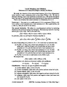
Avoid other robots: This behaviour results in a repulsive force between robots that normally allows to spread the robots around the environment. Avoid obstacles: Each cell within a specific range that is identified as belonging to an obstacle, applies a repulsive force over each robot. This range allows to easily adjust the system, but introduces a non-linearity. Go to imprecise landmarks: This behaviour tries to improve the quality of the exploration of those areas where some landmarks have been extracted but whose accuracy is not high enough. This allows to achieve a better map while the environment is explored by the team. Table 2.1 shows how the forces are calculated for each behaviour. The robots keep a constant linear speed. The heading of the robot is indicated by the direction of the resultant force. The resultant force is the combination of those five behaviours on each robot: F~kA = k1 F~k1 + k2 F~k2 + k3 F~k3 + k4 F~k4 + k5 F~k5 . (2.1) The composition of the behaviours is carried out taking into account a set of weights ki whose values have been deduced experimentally (Table 2.2). Fig. 2.1 shows the bird’s eye view of an exploring situation with three robots.
Table 2.2: Weights assigned to each behaviour. k1 k2 k3 k4 k5 1 2.5 0.8 40 1 Go To Frontier
30
Go To Unexplored Areas 25
Avoid Other Robots
(m)
Avoid Obstacles 20
Go To Imprecise Landmarks Resultant Force
15
Current Heading
Figure 3.1: Local potential field images for the exploring situation presented in the map. Robot 1 detects a local minimum.
10 −2
0
2
4
6
8
10
12
14
16
(m)
Figure 2.1: Weighted outputs of the behaviours and resultant force in an exploring situation. Also, the landmarks that have been detected until that moment are shown.
3. DETECTION AND ESCAPE FROM LOCAL MINIMA The potential field model described in the previous section allows to explore successfully simple environments. When we explore complex environments as, for example, a whole floor with corridors, some problems arise. Local minima are likely to appear in a typical situation where there exists a wall and there is a frontier behind it. When a local minimum appears the robot is blocked and it can not continue with the exploration. In this case the robot would stay there indefinitely until other robot removes this frontier, and meanwhile this robot would not contribute to the exploration. If all the robots get blocked by local minima then the exploration process stops.
3.1 Detection If there exist a local minimum in the potential field at a point, the resultant force in this point is zero. The kinematic constraints of the robot and the fact that it works with constant linear speed make that the robot does not go exactly to the local minimum. Instead of getting blocked, the robots move in circles trapped in the local minimum. For that reason, the condition that the resultant force is equal to zero can not be used as a local minima detector. Taking this fact into account, a local minimum could be detected when the movement traced by the robot in a given period of time falls below a small area of a specified size [8]. In this case, the time needed to detect
this situation is significantly high because it is necessary to wait this period of time before detecting a local minimum. In this article a faster method is presented. The method is based on the estimation of the potential field at the robot’s neighbourhood. The force field is defined as the gradient of the poten~ = ∇U ~ . We are interested in computing the tial field: F potential field based on the forces defined in Section 2. A discrete integration method is used to calculate it. We evaluate this potential field only at a small neighborhood area centered on the robot’s cell. As we need to evaluate all the forces for each cell in the neigbourhood, the smaller is this area the smaller is the potential field calculation time. In practice, a neighbourhood area of 7x7 cells was chosen. The resultant force is evaluated only for these neighbouring cells. The evaluation is made as if the robot were in that cell. They are integrated in the local potential field representation superposing a serial of small discrete surfaces centered on each cell with slope in the direction of the resultant force for each cell. The sum of the contribution for each cell in the neighbourhood area gives a bidimensional array that represents the potential field. Normalizing this array, the local potential field could be represented as a grey-level image where local minima can be observed with dark values. Figure 3.1 shows local potential field images obtained by this method in an exploring situation. As it can be observed in the figure, robot 1 is over a local minimum caused by a frontier behind a wall near it. In the local potential field representation for robot 1 could be clearly observed the minimum in the center of the image marked with black color. Once obtained the local field image for each robot it is easy to find local minima. At a normal exploring situation the minimum of the local potential field representation is placed at one of the exterior pixels of the image.
When the minimum is situated on a central pixel of the image a local minimum is detected. In this sense, the robot will be trapped at a local minimum when there exist a minimum in the central pixel.
3.2 Escaping from Local Minima In the previous section, a method to detect local minima was presented. It is now necessary to propose a method for escaping from this situation. In this sense, when a local minimum is detected, the robot switches to a new state in which it follows a planned path to a target point, that enables the robot to get out of the local minimum. This new state is triggered when a local minimum is detected. When the target cell is reached the robot returns to the potential field based exploration technique. The target cell could be set to the nearest frontier cell or following other of the assignment techniques used by the path planning approaches to the exploration problem. In this paper, a simple assignment to the nearest frontier cell is used. The A* algorithm [10] was used for path planning. The cost for moving from one cell to another √ is set to 1 for horizontal and vertical movements and 2 for diagonal movements. The total cost for a given cell is the sum of the cost of arriving to that cell and the estimated cost to the goal. This last cost is estimated heuristically as the euclidean distance from the cell to the goal. A set of cells obtained by graphically dilating the obstacle cells on the map (in order that the path planned keeps sufficiently far from the obstacles) in addition with the unexplored cells are set as forbidden (infinite cost) in the algorithm. Figure 3.2 shows on the left how the presence of local minima blocks an exploration process with four robots when the technique for detecting and escape from local minima is not used. As it was expected, most of the map remains unexplored. However, when using the proposed approach (right figure) the exploration is completed.
3.3 Trajectory Improvement Once solved the question of detecting and escaping from local minima, a second problem, consisting in the oscillation in the trajectories of the robots, came up in our method due to the presence of non linearities in the field. Non-linearities are introduced, mainly, by setting a maximum distance of influence in the Avoid Obstacles behavior. The maximum distance of influence was introduced in order to easily adjust the weights of the behaviors (There is no sense in avoiding obstacles when obstacles are far enough, but it is vital to avoid them when
Figure 3.2: Exploration blocked by local minima (left) and exploration with detection and escape from local minima (right). The exploration level is expressed in gray levels. The dark zones remain unexplored. The remaining frontier cells are also emphasized. they are close). This non linearity in the model of this behavior produces a discontinuity in the potential field at this maximum distance of influence of the obstacles. We control the robot by modifying its steering with the direction of the resultant force on the robot’s position while keeping linear speed constant. Using this control type the trajectory of the robot presents oscillations every time it travels over one of those discontinuities that appear near an obstacle. The oscillations are caused by the Avoid Obstacles force that appears only at one side of the discontinuity and repulses the robot from the obstacle. Once the robot is at the other side of the discontinuity this force disappears and the robot tries to cross the discontinuity again. To avoid this problem, the information of the potential field is used. Instead of modifying the steering of the robot with the direction of the resultant force on the position of the robot, the new steering will be set by the line that joins the center of the local potential field image with the external pixel with the minimum value. The dimension of the area of neighbourhood plays an important role in the control as it defines the level of filtering in the movements. It is not necessary to use the same dimension that the local minima detector. Figure 3.3 shows a detailed image of a robot trajectory travelling near a wall. In the left image, the oscillations in the robot’s trayectory when it travels over the discontinuity in the potential field are shown. The right picture shows the improvement in the trajectory when using the control system explained above and how it corrects the oscillating behaviour.
16
14
14
12
12
Y (m)
Y (m)
16
10
10
8
8
6
6
0
2
4
6 X (m)
8
10
12
0
2
4
6 X (m)
8
10
12
Figure 3.3: This figure shows the oscillations (left) over the non-linearities in the potential field and how the control system improvement allows to filter them (right). Figure 4.2: Mean number of cells per time unit for 3 to 7 robots in proposed method (black) and path planning method (grey).
Figure 4.1: Scenarios
4. EXPERIMENTS AND RESULTS In this section, we analyze simulation results using the exploration method proposed in this paper. To demonstrate the validity of the approach, it will be compared with a pure path planning approach. The scenarios chosen to test the method are shown in Figure 4.1. Scenarios that represent hypothetical real places like Scenario 1 or Scenario 2 were chosen at the same time that other artificial scenarios as for example Scenario 3 which may cause a lot of local minima or a completely random scene as Scenario 4. Note that each scenario is going to present a different number of frontiers during the exploration because of its structure. For example, Scenario 3 is more prone to present a greater number of frontiers than Scenario 2 as it has more bifurcations. The test was made changing the number of robots in the team in order to analyze the response for big and small groups. The test was repeated several times changing the initial positions. The mean number of cells explored per time unit was analysed for each scenario and number of robots. The exploration method proposed was always compared with a pure path planning approach, choosing always the nearest frontier as target point. Figure 4.2 shows the results of the test. It could be observed how each scenario presents a different exploration speed and it varies in a different way as the number of robots raises. Scenario 1 and Scenario 4 present faster exploration
speed when using the potential field approach in large groups of robots. The open space structure that both scenarios present improves the coordination when the number of robots increases. Remember that the unique coordination method included in the potential field approach is the Avoid Other Robots behavior which improves the exploration when robots have enough space to move apart from each other in the direction of the repulsion. The path planning approach is heavily affected by the number of frontiers that each scenario is able to present, the exploration speed saturates when the number of robots grow over the number of frontiers as could be seen for Scenario 1. Potential fields have better performance for small groups in Scenario 3. The great number of frontiers and the narrowness of the corridors make the exploration slower for the path planning method while the potential field approach is improved because of the structure of the scene that is favorable to the coordination. However, in this scenario a greater number of local minima is likely to appear when the number of robots raises, this fact reduces the performance for large groups. Scenario 2 is the slowest one, the disposition of the corridor is not favorable for the coordinating behavior Avoid Other Robots. Local minima reduce the performance of the potential field based method below the response for the path planning approach. As a conclusion, our approach is faster than path planning methods for large groups of robots on those scenarios that favour the coordination provided by the Avoid other Robots behavior.
5. CONCLUSIONS AND FUTURE WORK In this paper a method for multi-robot cooperative exploration has been presented. The method is based on the computation of a set of behaviours designed to rapidly explore the whole environment. As stated before, potential field methods have a main disadvantage: when exploring complex environments, a robot may be trapped at local minima in the potential field and may not move, thus stopping the exploration process. To solve this problem, we have presented a method that enables to detect the situation in which the robot is trapped at a local minimum. In this case, a new state is triggered that enables the robot to escape from the local minimum. Our approach considers the potential field at the robot’s neighborhood to detect local minima. In addition, the trajectories performed by the robot in the presence of nonlinearities in the field are improved by this method, obtaining straighter trajectories than those obtained with the basic behaviour-based method. Several simulation results demonstrate the validity of the approach. The approach presented allows tho explore the environment faster than path planning methods for large groups of robots on scenarios that favour the repulsion between robots. As future works we consider the extension of the approach in dynamic environments, adding techniques to learn automatically the multiple settings of the system. New behaviors will be incorporated in order to improve the localization when considering error in the localization of the robots. Furthermore, semi-operated models will be studied, that integrate the commands expressed by a human operator in the exploration task, where these commands would be taken as an advice.
ACKNOWLEDGMENT
[2] Stroupe, A.W.; Ravichandran, R.; Balch, T.: Valuebased action selection for exploration and dynamic target observation with robot teams. Proceedings. IEEE International Conference on Robotics and Automation, 2004, vol.4, pp. 4190-4197, April 26May 1, 2004 [3] Yamauchi B.: A Frontier Based Approach for Autonomous Exploration. IEEE International Symposium on Computational Intelligence in Robotics and Automation, Monterey, CA, July 10-11, 1997. [4] Simmons R., Apfelbaum D., Burgard W., Fox D., Moors M., Thrun S. and Younes H.: Coordination for multi-robot exploration and mapping. In Proceedings of the AAAI National Conference on Artificial Intelligence, Austin, TX, 2000. [5] Burgard W., Moors M., Stachniss C. and Schneider F.: Coordinated multi-robot exploration. IEEE Transactions on Robotics, Vol. 21 No3 pp 376-386, June 2005. [6] Zlot R., Stentz A., Dias M. B. and Thayer S.: MultiRobot Exploration Controlled By A Market Economy. Proceedings of the IEEE International Conference on Robotics and Automation, 2002. [7] Arkin R. and Diaz J.: Line-of-Sight Constrained Exploration for Reactive Multiagent Robotic Teams. 7th International Workshop on Advanced Motion Control, AMC’02 , Maribor, Slovenia, July 2002. [8] Lau H.: Behavioural Approach for Multi-Robot Exploration. Australasian Conference on Robotics and Automation (ACRA 2003), Brisbane, December 2003. [9] Mart´ınez Mozos O., Gil A., Ballesta M., and Reinoso O.: Interest Point Detectors for Visual SLAM. Proc. of the Conference of the Spanish Association for Artificial Intelligence (CAEPIA), Salamanca, Spain, November 2007.
This work has been supported by the Spanish Govern- [10] Hart P. E., Nilsson N. J. and Raphael B.: A Formal Basis for the Heuristic Determination of Minimum ment (Ministerio de Educaci´on y Ciencia). Project: ’SisCost Paths. IEEE Transactions on Systems Science temas de percepci´on visual m´ovil y cooperativo como soand Cybernetics SSC4 (2): pp. 100107, 1968. porte para la realizaci´on de tareas con redes de robots’. Ref.: DPI2007-61197. REFERENCES [1] Howard A., Parker L.E. and Sukhatme G.S.: The SDR experience: Experiments with a large-scale heterogenous mobile robot team. In Proc. of the International Symposium on Experimental Robotics, 2004.