Measurement Unit (IMU) and a Laser-based Vision System. (LVS). The LVS .... and distinguish true linear acceleration from angular acceleration and body roll or ...
�����0HGLWHUUDQHDQ�&RQIHUHQFH�RQ�&RQWURO�DQG $XWRPDWLRQ��-XO\����������������$WKHQV���*UHHFH
7������
Localization of an Underwater Vehicle using an IMU and a Laser-based Vision System George C. Karras, Kostas J. Kyriakopoulos National Technical University of Athens, School of Mechanical Eng, Athens, Greece
Abstract— This paper describes the development of a position tracking system designed for a Remotely Operated Vehicle (ROV). The sensor package consists of an Inertial Measurement Unit (IMU) and a Laser-based Vision System (LVS). The LVS consists of two undewater Laser pointers and a single CCD camera mounted on the ROV. The LVS fuses data deriving from the projection of the laser pointers on the image plane while it tracks a target at the same plane using computer vision algorithms. The LVS calculates the position vector of the vehicle at a low frequency, with respect to the center of the tracked object. The IMU measures the accelerations and angular velocities of the vehicle at a high frequency. The fusion of the two sensors is based on a Multisensor Kalman filter where the measured acceleration and angular velocity of the IMU is fed directly to the filter. The result is the calculation of the position vector at a high frequency, which can be used for a smooth closed loop steering control of the vehicle. The integration of the system was proved successful through an extensive experimental procedure. Keywords: Laser pointers, underwater vision, IMU, ROV, Multisensor Kalman Filter, guidance and control
I. I NTRODUCTION The use of underwater robotic vehicles in oceanic surveys, inspections, pipe and cable tracking, has been established in the field of marine engineering since many years before. An underwater vehicle may carry a variety of sensors depending on the technology of the vehicle and the requirements of the mission. The main role of the above sensors is to provide the vehicle steering controller with a sufficient position vector during a navigation or a stabilization process. Two common categories of navigation sensors are dead reckoning sensors and external sensors. Dead reckoning sensors provide robust and high frequency navigation data but accumulate errors with time, while external sensors provide absolute information and bound navigation errors but output at low frequency. These two types of sensors are usually integrated into one system to overcome their respective weakness and to fully utilize their strengths. The most common dead reckoning sensor an underwater vehicle carries is the IMU. An IMU measures the linear acceleration and the angular velocity of the vehicle using three accelerometers and three gyroscopes. Typical underwater external sensors used to correct accumulated errors from the integration of the IMU measurements, are Doppler Velocity Log Sensors (DVL), Ultra Short Baseline (USBL) and Differential Global Position Systems (DGPS/GPS) in the case where the vehicle is operating at shallow waters. Usually underwater vehicles operate in extremely difficult circumstances,
������������;����������������,(((
such as the inspection of a ship hull or a propeller shaft. Under such circumstances where centimeter precision is required, the previous mentioned external sensors may not be able to provide the navigation system with correct information due to low resolution and/or limited strength of the acoustic signal. In such cases a combination of devices like cameras and laser pointers can provide a sufficient position estimation, with limited working range but more accurate measurements and at higher frequency than an acoustic sensor. Many studies related on the use of IMU have been reported. These studies were mainly concerned with the GPS/IMU integration especially using a Kalman Filter [1], [2]. Also an important work has been done in the initial calibration and alignment of an IMU [3]. In [4] a GPS/IMU integration is proposed for an autonomous land vehicle, estimating the position and velocity of the vehicle feeding a Multisensor Kalman filter directly with the accelerations measured from the IMU. The integration of DVL/IMU for an underwater vehicle was studied in [5], [6] using a Kalman filter. Laser ranging systems can be found in a variety of previous studies. In [7] a methodology of orientation estimation is introduced projecting a laser stripe on the image plane. An approach for developing a ranging system using a single laser pointer was made in [8]. Moreover in [9] a methodology was introduced in order to correct the perpendicular distance and the yaw angle of an underwater vehicle using two laser pointers. In [10] a target-referenced localization of an underwater vehicle is proposed using stereoscopic cameras, and the orientation estimation was made using a compass and an inclinometer. The purpose of this paper is to introduce a methodology for defining the position and velocity vector of an ROV, using a Laser-based Vision System (LVS) and the accelerations and angular velocities measured from a low cost IMU. The LVS calculates the position vector of the vehicle with respect to a target - referenced coordinate system at a low frequency. In parallel the IMU measures the inertial linear accelerations and angular velocities of the vehicle at a high frequency. Then both sensors data are fused in a system that is based on a Multisensor Kalman Filter (MKF). The experimental results prove that the position vector calculated by the MKF, can be successfully used as the feedback input in a closed loop position control system. In addition, the experimental results show that the system is able to calculate a satisfactory estimate of the position and velocity
�����0HGLWHUUDQHDQ�&RQIHUHQFH�RQ�&RQWURO�DQG $XWRPDWLRQ��-XO\����������������$WKHQV���*UHHFH
7������
Fig. 3.
Fig. 1.
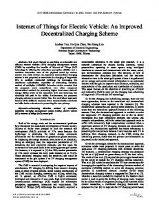
Calculation of x position and ψ orientation
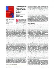
Body-fixed and earth-fixed reference frames
ν=
£
u
υ
w
r
¤T
(4)
A. Laser based Vision System (LVS)
Fig. 2.
Laser mount
vector of the vehicle, even though there is no update measurement from the LVS for a period of approximately 10 sec, which is a significant delay considering an error convergence requirement of centimeter precision in a dynamically unstable environment. The vehicle used is a 3-degrees of freedom (DOF) ROV (VideoRay Pro, VideoRay LLC). The paper is organized as follows: Section II gives a description of the methodology proposed, with the appropriate segregation of the distributed sub-problems. Section III illustrates the efficiency of the approach through a number of experimental results, while Section IV concludes the paper. II. M ETHODOLOGY Generally the position vector of a marine vehicle, with respect to an earth-fixed frame, is defined as follows: n = [x y z φ θ ψ]T
(1)
where x, y, z stand for the position and φ, θ, ψ for the orientation of the vehicle (Fig.1) Similarly the velocity vector is defined as follows: £ ¤T ν= u υ w p q r (2)
where u, υ, w stand for the linear and p, q, r for the angular velocities of the vehicle [11]. The ROV used, is a 3 DOF non holonomic vehicle and the angles and angular velocities about y and x axes are statically stable and equal to zero due to the vehicle configuration. So the position and velocity vectors of this vehicle can be rewritten as follows: n = [x y z ψ]T
(3)
The LVS system consists of a CCD camera and two laser pointers which are parallel to the camera axis (Fig.2). The LVS calculates the position vector of the vehicle with respect to the center of a target which lies on the image plane and is selected interactively by the user. Each laser pointer projects a high intensity dot on the surface the target lies on. The two laser dots are visible in the optical field of the camera. Through an experimental procedure a mapping between the position of each laser dot on the image plane, and the range of the laser pointer from the target plane is obtained. The mapping is achieved by polynomials instead of the triangulation technique, which is subject to inaccurate results due to hardware constraints. Using the ranges of each laser pointer and their distance (i.e L1 , L2 , dH respectively as shown in Fig.3), the position along the x-axis and the orientation about z-axis (yaw angle) of the vehicle can be computed [14]. The target is tracked by using the Active Contours computer vision algorithm [12]. The Active Contours are usually known as Snakes. A Snake is an energy minimizing spline guided by external constraint forces, and influenced by image forces that pull it toward features such as lines and edges. The Active Contours algorithm is implemented in the system software. The streaming video is acquired from the ROV camera. Using the mouse pointing device, a user draws a circle inside the image. The implemented software gives the ability to the user to choose where to place the center of the circle and adjust its radius, by using only the computer mouse. The circle is then used as the spline. The user draws the circle in order to enclose the target. With a simple mouse click the Active Contours algorithm is applied, the circle is being attracted by the target, locks onto its edges and localize it accurately (see Fig.4). The position of the Snake is controlled via the spline control points. The center of the Snake (sx , sy ) coincides with the center of the target. The next step is to combine the information provided by the two laser pointers and the Active Contours computer vision algorithm with the camera calibration model equations. The result is the calculation of the position along the y and z axis. The complete position vector with
�����0HGLWHUUDQHDQ�&RQIHUHQFH�RQ�&RQWURO�DQG $XWRPDWLRQ��-XO\����������������$WKHQV���*UHHFH
7������
is the known state transition matrix. In the simplest case the measurements are expressed as a linear relation with respect to the state space variables and are corrupted by noise. The measurements for a set of N sensors are given by the following equation: zik = Hi xk + bik , i = 1...N
Fig. 4.
with zik ∈