Lock-in Elimination by Orthogonal Polarization in Semiconductor Ring Laser Gyroscope Arpit Khandelwal, Azeemuddin Syed
Jagannath Nayak
Centre for VLSI and Embedded Systems Technology International Institute of Information Technology Gachibowli, Hyderabad, India - 500032 E-mail:
[email protected]
Inertial Systems Group, Research Center Imarat Defence Research and Development Organization Hyderabad, India - 500069
Abstract— We propose a novel method to eliminate the lock-in in a S emiconductor Fiber Ring Laser Gyroscope by orthogonally polarizing the counter-traveling waves in the ring cavity. Orthogonal polarization reduces the coupling between the waves which prevents them from locking. Keywords— Semiconductor ring laser gyroscope, lock-in, orthogonal polarization.
I. INT RODUCT ION Fiber optic Semiconductor Ring Laser Gyroscope (SRLG) is an inertial rotation sensor consisting of a Semiconductor Optical Amplifier (SOA) as the gain medium and a single mode optical fiber forming the external ring cavity [1]. It works on the principle of Sagnac Effect [2], which states that inertial rotation causes a frequency difference between two counter-traveling waves in a closed ring cavity. The magnitude of the frequency difference is proportional to the angular velocity of rotation and can be measured by external interference of the waves. In SRLG, the counter-traveling waves in the clockwise (CW) and counter-clockwise (CCW) direction are produced by the SOA and the external ring cavity is formed a single mode optical fiber. The compact size, low cost and low power consumption of SRLG have made it an attractive alternative to the bulky and costly He-Ne RLG [3]. Many different configurations of SRLG have been experimentally proposed, implemented and analyzed. Several modifications have been made in order to improve the performance of the SRLG but still the performance levels of SRLG have not matched to those of He-Ne RLG [4]. Thus, although SRLG is extensively used in some low performance applications like automobiles and robotics, high performance areas like navigation are still dominated by He-Ne RLG [4]. Various performance limiting phenomena in SRLG have been found out such as lock-in, gain competition [5], spatial and spectral hole burning [6,7]. But out of these, the primary drawback of SRLG which limits its ability to achieve high performance is the lock-in occurring at low rotation rates [8].
lower limit in the measurement sensitivity of the gyro which is known as lock-in threshold. The main reason for the lock-in in RLG is the coupling between the CW and CCW waves [8]. The coupling leads to energy exchange between them which causes them to oscillate at same frequency. This coupling is also present in He-Ne RLG, but its magnitude is very small because of the Doppler Broadening of the gaseous gain medium [10]. On the other hand, semiconductor gain medium is homogeneously broadened which leads to a much greater coupling between CW and CCW waves due to gain grating formation and cross saturation effects [10].
Lock-in is a phenomenon which occurs in a RLG at low inertial rotation rates. When the velocity of inertial rotation is lower than a certain threshold, the CW and CCW waves fail to oscillate independently and are locked at the same frequency. Thus, the beat signal corresponding to the small rotation rate is lost and hence rotation cannot be measured [9]. This leads to a
In this work, we propose a novel configuration to eliminate the coupling between the CW and CCW waves inside the SOA. This is achieved by polarizing the CW and CCW waves orthogonally to each other to reduce the interaction between them. The reduced coupling will prevent any energy exchange between the waves and will effectively eliminate lock-in
978-1-4673-6981-7/ 15/$31.00 ©2015
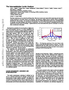
Fig. 1 Proposed SRLG configuration
Fig. 2 Output of SOA
Fig. 4 CCW wave after passing through FR
between them. This method can help to increase the sensitivity of the SRLG and improve its performance. II. PROPOSED CONFIGURAT ION AND WORKING The proposed experimental setup is shown in Fig. 1. Here, SOA is the semiconductor gain medium producing CW and CCW waves traveling in the external fiber cavity. As the SOA has wide amplification bandwidth, a filter is used to lower the bandwidth of operation and thus reduce the number of longitudinal modes oscillating simultaneously in the ring cavity. This is essential to reduce the undesired mode competition. Two non-reciprocal Faraday Rotators (nFR) are used to rotate the plane of polarization of the counter-traveling waves. A Yjunction coupler is used to interfere the two waves to obtain the beat signal. The photodiode (PD) converts the optical beat signal to an electrical signal which is analyzed on a spectrum analyzer (SA). The spectrum analyzer gives a sharp spike at the beat frequency which is used to calculate the rotation rate. For more accurate and completely digital measurements, spectrum analyzer can be replaced by a FFT module. The non-reciprocal Faraday Rotators are placed in two different fiber rings. One is placed in the ring cavity containing the gain medium (active cavity) and the other is placed in the ring containing the Y-junction coupler (passive cavity). This is done so that the CW and CCW waves can be brought into same
Fig. 3 CW wave after passing through FR
Fig. 5 Interaction of CW and CCW waves inside SOA
eigen state of polarization (ESOP) before they are interfered to obtain the beat signal. Also, both the rotators have opposite angles of rotation i.e.
450 and 450 .
Since the Faraday Rotators are non-reciprocal, the direction of rotation of the plane of polarization is opposite for the light waves entering from opposite ends. Thus, it can be seen from Fig. 1 that the plane of polarization of CW wave in the active ring cavity will be rotated by
450 and that of the CCW
wave will be rotated by 45 . Assuming the output of semiconductor gain medium to be linearly polarized, the corresponding ESOPs of the CW and CCW waves after passing through the FR are also shown in Fig. 1. 0
On the other hand, in the passive ring cavity, the plane of polarization of the CW wave will be rotated by
450 and
that of the CCW wave will be rotated by 45 . Thus, from Fig. 1, it can be seen that the two counter-traveling waves entering the gain medium SOA are orthogonally polarized to each other and those entering the output Y-junction coupler are polarized in the same direction. 0
III. M AT HEMAT ICAL REPRESENT AT ION The initial output of the SOA propagating in the z direction with angular frequency and propagation constant k can be represented as
E E0 cost kz
(1)
In order to represent the polarization of light waves and the transfer functions of polarization dependent elements we use the Jones Vectors [11]. Thus, assuming the initial output of the laser to be linearly polarized with angle of polarization , the amplitude of the wave in terms of Jones vector will be
cos E0 sin
(2)
Now, the Jones vector for the Faraday Rotator of an angle given as
cos sin F sin cos
is
(3)
When the light from SOA passes through the Faraday Rotator, its plane of polarization gets rotated by and its Jones vector now becomes
cos sin cos (4) E0 sin cos sin
cos E0 sin
450 in the X-Y plane. Fig. 3 and 4 show the CW and CCW after passing through the Faraday Rotator whose transfer function is given by (3). It can be clearly seen from the figures that the two waves are orthogonally polarized to each other as represented by (6) and (7). Finally, Fig. 5 shows the interaction of the CW and CCW waves inside the semiconductor gain medium after passing through the rotator. It can be seen that there is no interaction between the waves and hence they do not couple inside the gain medium as represented in (8). The ESOPs of the CW and CCW waves at the Y-junction coupler are along the same direction and hence they will interfere with each other to produce a signal at the beat frequency through which rotation can be sensed. V. CONCLUSIONS We have shown that the coupling between two counter-traveling CW and CCW waves inside the gain medium can be eliminated by orthogonally polarizing them. This eliminates the exchange of energy between the waves and thus helps to lower the lock-in threshold of the SRLG. Small amount of coupling can take place in the passive ring cavity leading to lock-in at very low rotation rates. A further improvement in the performance can be obtained be including a birefringent medium in the active ring. The birefringent medium will have different path lengths for CW and CCW waves of different ESOPs, which will inherently bias the gyro.
(5)
In our case, for the CW wave in the active loop,
450 and 450 . Similarly, for CCW wave, 450 and 450 . Thus the corresponding Jones vectors for the CW
and CCW waves are given by
cos 0 1 Ecw sin 0 0
(6)
cos 90 0 Eccw sin 90 1
(7)
When the CW and CCW waves interact in the gain medium after passing through FR, their resultant Jones vector becomes
1 * Eres Ecw Eccw 0 1 0 (8) 0 Thus, above equation (8) states that there is no resultant interaction and coupling between the CW and CCW waves inside the gain medium. IV. SIMULAT ION RESULT S The simulations of the above equations were performed and the results are shown in Fig. 2 – Fig. 5. Fig. 2 shows the initial output of the SOA which is assumed to be linearly polarized with the plane of polarization oriented along
REFERENCES [1]
Kozo T aguchi, Kaname Fukushima, Atsuyuki Ishitani, and Masahiro Ikeda, "Proposal of a semiconductor ring laser gyroscope," Opticaland quantum electronics, vol. 31, no. 12, pp. 1219-1226, 1999. [2] E. J. Post, “Sagnac effect,” Reviews of Modern Physics, vol.39,no.2,pp. 475, 1967. [3] M. N. Armenise, C. Ciminelli, F. Dell’Olio abd V. M. Passaro, Advances in gyroscope technologies, Springer Science and Business Media, 2010. [4] Caterina Ciminelli, Francesco Dell’Olio, Carlo E. Campanella,andMario N. Armenise, "Photonic technologies for angular velocity sensing," Advances in Optics and Photonics, vol. 2, no. 3, pp. 370-404, 2010. [5] Fuad Rawwagah, and Surendra Singh. "Nonlinear dynamics of a modulated bidirectional solid-state ring laser." JOSA B vol. 23, no.9 pp. 1785-1792, 2006. [6] Richard Schatz, "Longitudinal spatial instability in symmetric semiconductor lasers due to spatial hole burning." Quantum Electronics, IEEE Journal of , vol. 28, no. 6, pp. 1443-1449, 1992. [7] A. Uskov, Jesper Mørk, and Jannik Mark, "Wave mixing in semiconductor laser amplifiers due to carrier heating and spectral-hole burning." Quantum Electronics, IEEE Journal of, vol. 30, no. 8, pp. 1769-1781, 1994. [8] E. L Klochan, L. S. Kornienko, N. V. Kravtsov, E. G. Lariontsev,andA. N. Shelaev. "Oscillation regimes in a rotating solid-state ring laser." Zhurnal Eksperimentalnoi i Teoreticheskoi Fiziki, vol.65,pp.1344-1356, 1973. [9] W. W. Chow, J. Gea-Banacloche, L. M. Pedrotti, V. E. Sanders, Wo Schleich, and M. O. Scully, "T he ring laser gyro," Reviews of Modern Physics vol. 57, no. 1, pp. 61, 1985. [10] Anthony Siegman, Lasers, University Science Books, Mill Valley, 1986. [11] R. Clark Jones, "A new calculus for the treatment of optical systems." JOSA, vol. 31, no. 7, pp. 488-493, 1941.