Surface Reflection Elimination in Polarization Imaging of Superficial. Tissue. Stephen P. Morgan and Ian M. Stockford. School of Electrical and Electronic ...
Optics Letters 02/2003; 28(2):114-6. DOI:10.1364/OL.28.000114
Surface Reflection Elimination in Polarization Imaging of Superficial Tissue
Stephen P. Morgan and Ian M. Stockford. School of Electrical and Electronic Engineering, University of Nottingham, Nottingham, NG7 2RD, UK.
Abstract A major drawback in polarization gating of light backscattered from tissue is that surface reflections dominate the image. An optically flat plate and matching fluid applied to the tissue surface, combined with off-axis detection has previously been used to address this problem. This is often inappropriate or inconvenient for practical use and more importantly can affect the tissue optical properties. A method is demonstrated which combines images obtained with linearly and circularly polarized light to produce a polarization gated image that is free from surface reflections and does not require optically flat plates or matching fluid.
OCIS codes: (170.0170) Medical optics and biotechnology; (260.5430) Polarization.
1
Optics Letters 02/2003; 28(2):114-6. DOI:10.1364/OL.28.000114
Light scattering by tissue gradually randomizes the original polarization state of the illuminating light. Unscattered or weakly scattered light maintains its original polarization state whereas multiple scattered light is randomly polarized and contributes equally to both co- and cross- polarization states. A simple subtraction of co- and crosspolarization states removes the multiple scattered background and enables the weakly scattered component to be extracted. Polarization gating has been demonstrated as a simple and effective method of improving image resolution and extracting light that has propagated only within superficial tissue1-5. This light can potentially be used to characterize skin lesions and is the subject of current research for several groups2-5.To determine the diagnostic potential of polarized light techniques is beyond the scope of this letter, the contribution of this letter is to demonstrate a new method for eliminating surface reflections. A common method of eliminating surface reflections in conventional reflection mode imaging of tissue is to detect in cross polars6,7, however, this is inappropriate for polarization imaging as the co-polar component contains light that has propagated only through superficial tissue. An alternative approach is to apply an optically flat plate and matching fluid to the tissue and position the detector off-axis to the illumination5,8. This results in light from the surface being specularly reflected at the flat interface and not being detected. This is often inconvenient for clinicians and patients, and inappropriate for the tissue under investigation e.g. burn or wound characterization. More importantly,
2
Optics Letters 02/2003; 28(2):114-6. DOI:10.1364/OL.28.000114
compression of the skin can alter its optical and physical properties and affect diagnosis by evacuating the blood vessels and distorting collagen architecture In this letter we describe a method of extracting light that has propagated only within superficial tissue while removing surface reflections using only polarized light subtraction. This obviates the need for matching fluid and optically flat plates. In addition the method enables co-axial detection, which often simplifies systems, for example in endoscopy illumination and detection can use the same fiber bundle.
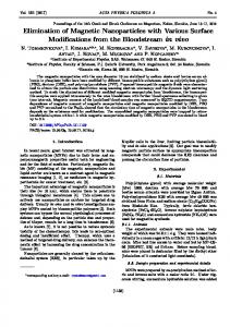
Fig. 1 demonstrates the different properties of light backscattered from linearly and circularly polarized illumination. For linearly polarized illumination (fig. 1a) both the surface reflection and weakly scattered light component maintain the original polarization state. Multiple scattered light is randomly polarized and contributes equally to both coand cross-linear polarization channels. Backscattered light from circularly polarized illumination has different properties (fig. 1b); light reflected directly from the surface undergoes a mirror reflection and emerges with its helicity reversed. Due to the highly forward scattering nature of tissue the majority of weakly scattered light maintains its original polarization state. However, it should be noted that there is a small proportion of light that emerges with its helicity reversed due to immediate backscattering from within the medium itself. Again multiple scattered light contributes equally to both co- and cross- circular polarization channels. The different detection channels and the properties of the emerging light in these channels are summarized in table 1.
3
Optics Letters 02/2003; 28(2):114-6. DOI:10.1364/OL.28.000114
The key to the technique described is the observation that circularly polarized illumination (channels 3 and 4) separates surface reflected light from weakly scattered light, whereas linearly polarized light (channels 1 and 2) does not. Conventional approaches1-5 subtract co- and cross-polarized components, usually channel 1 - channel 2. Channels 2 and 3 are states that are free from surface reflection and therefore performing a channel 3 - channel 2 subtraction allows both extraction of weakly scattered light and elimination of surface reflections. In a previous publication9 we have demonstrated using a polarization dependent Monte Carlo simulation that for typical tissue optical parameters the polarized light extracted using this technique corresponds to a depth of 7 scattering mean free paths (MFP) beneath the surface. It should be noted that due to polarization memory effects10,11 the depth defined by the circular polarization gate is larger than that defined by a linear polarization gate.
The experimental set up used to measure light in the four polarization channels is shown in fig. 2. Laser light (λ = 633nm) is passed through a rotating diffuser (ground glass disc) to eliminate speckle from the images. The polarization state of the light illuminating the sample is set by a quarter waveplate and linear polarizer. Light backscattered from the sample is analyzed using another quarter waveplate and linear polarizer before being imaged onto a CCD camera. The exposure time of the CCD is fixed at 64s for each polarization image and images are directly subtracted from one another, without any normalization. The scattering phantoms used are a suspension of polystyrene microspheres (g = 0.97, μs = 20mm-1) in a cuvette of dimensions 10mm x 47mm x 42mm.
4
Optics Letters 02/2003; 28(2):114-6. DOI:10.1364/OL.28.000114
To demonstrate the depth discrimination properties of the polarization gate we image an absorbing object (totally absorbing Perspex disc, diameter = 3mm, attached to a transparent Perspex rod) at three different depths (2, 10, 22 MFPs) within the medium. The depths are chosen to fall within the gates for linear, circular and multiple scattered light estimated from Monte Carlo simulations9. Clearly, these depths are less than the pathlength required to randomize the polarization state (i.e. 1 transport mean free path for linear polarization) as the imaging is in reflection geometry and photons emerging with pathlengths shorter than this distance contribute to the polarization maintaining component. Phantom images are shown in fig. 3 for light extracted using linear polarization subtraction (channel 1 – channel 2), circular polarization subtraction (channel 3 – channel 2) and multiple scattered light (channel 2 only) at the three different depths. The first object depth (2 MFPs, 1st column) is chosen such that the object falls within the depth defined by the linear polarization gate and therefore the object is visible in all images. At the second depth (10 MFPs, 2nd column) the object is no longer visible in the linear polarization image but is still visible in the other two. At the final depth (22MFPs, 3 rd column) the object is barely visible in the circular polarization image but is still visible in the multiple scattered light image. These results demonstrate the effect of the depth discrimination properties of the different polarization gates but do not show elimination of surface reflections as the surface of the cuvette is optically flat and detection is performed off-axis. It is therefore important to demonstrate the technique in a practical environment where surface reflections are a significant problem. Fig. 4 demonstrates images taken in the four
5
Optics Letters 02/2003; 28(2):114-6. DOI:10.1364/OL.28.000114
polarization channels, described in table 1, of a lentigo on a 31 year old, Caucasian male. As can be seen from the images in channels 1 and 4 (figs 4a and d) there is significant contribution from the surface. Channels 2 and 3 (figs 4b & c) contain no significant surface reflection and the difference in intensity between them can be attributed to weakly scattered, circularly polarized light. A linear subtracted image (channel 1 – channel 2) is shown in fig. 4e. The image is clearly dominated by the surface reflection, which provides no information about the underlying tissue and distorts conventional polarization images. A subtracted image (channel 3 – channel 2), containing light that has propagated only through superficial tissue but free from surface reflection is shown in fig 4f.
The polarization subtraction method described has been demonstrated to be an effective method of imaging superficial tissue. It is the subject of current research to determine whether polarization imaging is a useful tool for skin characterization. Previous methods5 have required off-axis detection whereas this approach eliminates surface reflections using polarization so on-axis detection is possible. For example a beamsplitter and a single set of polarizing optics could be used to simplify the system. In addition on-axis detection could be useful in endoscopy where illumination and detection could be performed using the same fiber bundle. It should be noted that some researchers1-4 choose to use a direct subtraction of polarization states so that absorption information from the polarized maintaining light can be obtained whereas others5 prefer to normalize the image by the total intensity in attempt to negate the effects of absorption. The former approach may yield spectroscopic
6
Optics Letters 02/2003; 28(2):114-6. DOI:10.1364/OL.28.000114
information whereas the latter may enhance scattering effects. We choose to demonstrate the surface reflection technique using the former but the approach is valid for both methods. Using the approach of taking images consecutively at different rotations of the quarter waveplates and polarizers makes the technique susceptible to movement artifacts. However, these effects could be eliminated by simultaneously imaging both co- and cross polar channels with a polarizing beamsplitter and fast switching the input polarization state using either a spatial light modulator or Pockels cell. It should also be noted that due to polarization memory effects9-11 the extracted circularly polarized light has probed slightly deeper than that probed by linearly polarized light and that this may vary for different tissue types. Previously we have demonstrated9 that the peak depths probed by linearly and circularly polarized light are 200m and 700m respectively for typical tissue optical properties. In addition the polarization memory effects mean that the amount of multiple scattered light is different in channels 2 and 3. However, this difference is relatively insignificant and the majority of multiple scattered light is eliminated to provide localization beneath the surface. In inhomogeneous tissue polarisation memory effects may be less prominent making the performance of linear and circular discrimination comparable; this is a study of current research.
A method of removing both light reflected from the tissue surface and light multiple scattered from deeper tissue using only the polarization properties of the backscattered light has been demonstrated. The technique is based upon the different scattering
7
Optics Letters 02/2003; 28(2):114-6. DOI:10.1364/OL.28.000114
properties of linear and circular polarization states. Performing a subtraction of the two backscattered polarization channels that do not contain a surface reflected component results in the extraction of weakly scattered light that has probed superficial tissue. This component is important for skin characterization. This method obviates the need for optically flat plates and matching fluid to be applied to the tissue. In addition on-axis detection is possible, which enables simpler optical systems to be developed.
References 1. J.M.Schmitt, A.H.Gandjbakhche and R.F.Bonner, Appl. Opt. 31, 6535 (1992). 2. S.G.Demos and R.R.Alfano, Appl. Opt. 36, 150 (1997). 3. S.G.Demos, H.B.Radousky and R.R.Alfano, Opt. Express 7, 23 (2000), http://www.opticsexpress.org/opticsexpress/ framestocv7n1.htm 4. S.P.Morgan, M.P.Khong and M.G.Somekh, Appl. Opt. 36, 1560 (1997). 5. S.L.Jacques, J.R.Roman and K.Lee, Lasers in Surg. & Med. 26, 119 (2000). 6. R.R. Anderson, Arch. Dermatol. 127, 1000 (1991). 7. W Groner, JW Winkelman, AG Harris, C Ince, GJ Bouma, K Messmer, RG Nadeau, Nature Med. 5, 1209 (1999). 8. W. Stolz, O. Braun-Falco, P. Bilek, M. Landthaler and A.B. Cognetta, Color Atlas of Dermatoscopy, Blackwell Science, (1993). 9. I.M.Stockford, S.P.Morgan, P.C.Y.Chang, J.G.Walker, to be published in J. Biomedical Optics, July 2002.
8
Optics Letters 02/2003; 28(2):114-6. DOI:10.1364/OL.28.000114
10. F. C. MacKintosh, J. X. Zhu, D. J. Pine, and D. A. Weitz, Phys. Rev. B 40, 9342 (1989). 11. S.P. Morgan and M.E. Ridgway, Opt. Expr. 7, 540 (2000).
Figure Captions Fig. 1 a) linear illumination & detection b) circular illumination & detection. Polarization maintaining light is localised in region 1, multiple scattered light propagates through deeper tissue (region 2). Circular polarization discriminates between polarization maintaining and surface reflected light. Fig. 2 Experimental set up. Laser light passes through a rotating ground glass diffuser. The polarization state of the illuminating light is set using a linear polarizer and quarter waveplate. Light emerging from the sample is analyzed before being imaged onto a CCD camera. Fig. 3 Images of object located at different depths (1st column – 2 MFPs, 2nd column – 10 MFPs, 3rd column – 22 MFPs) for different polarization gates (row 1 – linear polarization gate, row 2 – circular polarization gate, row 3 – multiple scattered light). Fig.4 Image of a lentigo in a) channel 1 b) channel 2 c) channel 3 d) channel 4 e) channel 1 – channel 2 f) channel 3 – channel 2
9
Optics Letters 02/2003; 28(2):114-6. DOI:10.1364/OL.28.000114
Full References 1. J.M.Schmitt, A.H.Gandjbakhche and R.F.Bonner, "Use of polarized light to discriminate short-path photons in a multiply scattering medium," Appl. Opt. 31, 6535 (1992). 2. S.G.Demos and R.R.Alfano, "Optical polarization imaging," Appl. Opt. 36, 150 (1997). 3. S.G.Demos, H.B.Radousky and R.R.Alfano, Opt. Express 7, 23 (2000), http://www.opticsexpress.org/opticsexpress/ framestocv7n1.htm 4. S.P.Morgan, M.P.Khong and M.G.Somekh, "Effects of polarization state and scatterer concentration on optical imaging through scattering media," Appl. Opt. 36, 1560 (1997). 5. S.L.Jacques, J.R.Roman and K.Lee, "Imaging superficial tissues with polarized light," Lasers in Surg. & Med. 26, 119 (2000). 6. R.R. Anderson, Arch. Dermatol. 127, 1000 (1991). 7. W Groner, JW Winkelman, AG Harris, C Ince, GJ Bouma, K Messmer, RG Nadeau, Nature Med. 5, 1209 (1999). 8. W. Stolz, O. Braun-Falco, P. Bilek, M. Landthaler and A.B. Cognetta, Color Atlas of Dermatoscopy, Blackwell Science, (1993). 9. I.M.Stockford, S.P.Morgan, P.C.Y.Chang, J.G.Walker, “Analysis of the spatial distribution of polarized light backscattered from layered scattering media,” to be published in J. Biomedical Optics, July 2002. 10. F. C. MacKintosh, J. X. Zhu, D. J. Pine, and D. A. Weitz, "Polarization memory of multiply scattered light," Phys. Rev. B 40, 9342 (1989).
10
Optics Letters 02/2003; 28(2):114-6. DOI:10.1364/OL.28.000114
11. S.P. Morgan and M.E. Ridgway, "Polarization properties of light backscattered from a two layer scattering medium," Opt. Expr. 7, 540 (2000).
11
Optics Letters 02/2003; 28(2):114-6. DOI:10.1364/OL.28.000114
Polarisation maintaining
Linear Illumination
Surface reflection 1
Polarisation maintaining
Circular Illumination
Surface reflection Multiple scattered
Multiple scattered
1 2
2
Fig. 1 a) linear illumination & detection b) circular illumination & detection. Polarization maintaining light is localised in region 1, multiple scattered light propagates through deeper tissue (region 2). Circular polarization discriminates between polarization maintaining and surface reflected light.
12
Optics Letters 02/2003; 28(2):114-6. DOI:10.1364/OL.28.000114
Fig. 2 Experimental set up. Laser light passes through a rotating ground glass diffuser. The polarization state of the illuminating light is set using a linear polarizer and quarter waveplate. Light emerging from the sample is analyzed before being imaged onto a CCD camera.
13
Optics Letters 02/2003; 28(2):114-6. DOI:10.1364/OL.28.000114
Fig. 3 Images of object located at different depths (1 st column – 2 MFPs, 2nd column – 10 MFPs, 3rd column – 20 MFPs) for different polarization gates (row 1 – linear polarization gate, row 2 – circular polarization gate, row 3 – multiple scattered light).
14
Optics Letters 02/2003; 28(2):114-6. DOI:10.1364/OL.28.000114
a)
b)
c)
d)
e)
f)
Fig.4 Image of a lentigo in a) channel 1 b) channel 2 c) channel 3 d) channel 4 e) channel 1 – channel 2 f) channel 3 – channel 2
15
Optics Letters 02/2003; 28(2):114-6. DOI:10.1364/OL.28.000114
Table 1: Polarization discriminating detection schemes
Channel
Illumination
Detection
1
Linear
Co - Linear
Categories of light Surface reflected, Polarization maintaining and multiple scattered light
2
Linear
Cross - Linear
Multiple scattered light
3
Circular
Co - Circular
4
Circular
Cross - Circular
16
Polarization maintaining and multiple scattered light Surface reflected, mirror reflected scattered and multiple scattered light