The illustrations, charts, sample programs and layout examples shown ... The
Logix5000 controller stores data in tags, in contrast to a PLC-5 controller, which ...
Reference Manual
Logix5000 Data Access
Purpose
This documents describes how to access data from a Logix5000 controller using the following methods: • CIP Services (inherent Logix5000 mode of communications) • Programmable Controller Communication Commands (PCCC), for compatibility with PLC and SLC controllers: – PLC-2 Commands – PLC-5 Commands – SLC Commands
When to Use this Document
Use this document when you need to write data to or read data from a Logix5000 controller via an external device.
How to Use this Document
This document uses the following acronyms and definitions:
This term:
Means:
PLC-5
a type of Allen-Bradley Programmable Logic Controller
PLC-2
an older type of Allen-Bradley Programmable Logic Controller
SLC
an Allen-Bradley Small Logic Controller
CIP
Control and Information Protocol
GEN STS
CIP message general status
IOI
Internal Object Identifier (I.e., How to address data in CIP messaging.)
segment
Part of an IOI
tag
character name of data
STS / EXT STS
status of the message transmission
TNS
16 bit unique transaction identifier
address offset
a 2 byte field which indicates byte offset from the start of a file or tag
system address
a multi-byte field which indicates where to start the operation
packet offset
indicates how much further from system address to continue the operation
total transaction
indicates total extent of intended operation
For additional information, refer to the DF1 Protocol and Command Set Reference Manual, publication 1770-6.5.16.
1
Publication 1756-RM005A-EN-E - March 2000
2
Logix5000 Data Access
Important User Information
Because of the variety of uses for the products described in this publication, those responsible for the application and use of this control equipment must satisfy themselves that all necessary steps have been taken to assure that each application and use meets all performance and safety requirements, including any applicable laws, regulations, codes and standards. The illustrations, charts, sample programs and layout examples shown in this guide are intended solely for purposes of example. Since there are many variables and requirements associated with any particular installation, Allen-Bradley does not assume responsibility or liability (to include intellectual property liability) for actual use based upon the examples shown in this publication. Allen-Bradley publication SGI-1.1, Safety Guidelines for the Application, Installation and Maintenance of Solid-State Control (available from your local Allen-Bradley office), describes some important differences between solid-state equipment and electromechanical devices that should be taken into consideration when applying products such as those described in this publication. Reproduction of the contents of this copyrighted publication, in whole or part, without written permission of Rockwell Automation, is prohibited. Throughout this manual we use notes to make you aware of safety considerations:
ATTENTION
!
Identifies information about practices or circumstances that can lead to personal injury or death, property damage or economic loss
Attention statements help you to: • identify a hazard • avoid a hazard • recognize the consequences IMPORTANT
Publication 1756-RM005A-EN-E - March 2000
Identifies information that is critical for successful application and understanding of the product.
Logix5000 Data Access
3
Table of Contents Logix5000 Data
4
CIP Services
5
Introduction
5
CIP Read Data Service
14
Read Data Fragmented Format Service
14
CIP Write Data Service
15
Write Data Fragmented Format Service
15
Multi-Request Service
16
Get Attributes List Service
17
Read Template Service
18
Addressing Examples
19
PLC-2 Commands
21
Unprotected Read
21
Protected Write
22
Unprotected Write
22
Protected Bit Write
22
Unprotected Bit Write
23
PLC-5 Commands
24
Read Modify Write
25
Read Modify Write N
26
Typed Read
27
Typed Write
27
Word Range Read
28
Word Range Write
29
Bit Write
29
SLC Commands
30
SLC Protected Typed Logical Read with 3 Address Fields
31
SLC Protected Typed Logical Write with 3 Address Fields
31
SLC Protected Typed Logical Read with 2 Address Fields
32
SLC Protected Typed Logical Write with 2 Address Fields
32
Appendix A: Map an Address
33
Publication 1756-RM005A-EN-E - March 2000
4
Logix5000 Data Access
Logix5000 Data
The Logix5000 controller stores data in tags, in contrast to a PLC-5 controller, which stores data in data files. Logix5000 tags have these properties: • name, which identifies the data: – up to 40 characters in length – does not include a file number • scope: – controller (i.e., global), which you can access directly – program (i.e., local), which you can not access via an external device • data type, which defines the organization of the data The Logix5000 controller supports a large variety of data types: • atomic: a bit, byte, 16-bit word, or 32-bit word, each of which stores a single value. • structure: a grouping of different data types that function as a single unit and serves a specific purpose. Depending on the needs of your application, you can create additional structures, which are referred to as user-defined structures. • array: a sequence of elements, each of which is the same data type: – You can define data in zero, one, two, or three dimensions, as required. (Zero or one dimension are the most common.) – You can use either atomic or structure data types. The following table identifies the predefined data types:
Publication 1756-RM005A-EN-E - March 2000
To store a:
Use this data type:
Structure
Bit
BOOL
Bit array
BOOLEAN ARRAY (32 bit chunks)
8 bit integer
SINT
16 bit integer
INT
32 bit integer
DINT
32 bit float
REAL
32 bits of milliseconds
TIMER
✓
32 bits of range
COUNTER
✓
32 bits of range
CONTROL
✓
Logix5000 Data Access
CIP Services
5
The following sections describe the inherent mode of communications and addressing of the Logix5000 controller. You can use the following services to access Logix5000 data: • • • • • • •
CIP Read Data Service Read Data Fragmented Format Service CIP Write Data Service Write Data Fragmented Format Service Multi-Request Service Get Attributes List Service Read Template Service
Introduction Before you use CIP services, review the following introductory information: • • • • • •
CIP Data Types IOI Segments Abbreviated Type Returned data formats with abbreviated types Array Indexing CIP Service Errors
Publication 1756-RM005A-EN-E - March 2000
6
Logix5000 Data Access
CIP Data Types Data type information is very important in all aspects of CIP communications. The type information is used for reading, writing, and, if necessary, deciphering structures. The following diagram shows the layout of the CIP data types.
15 14 13 12 11 10 9
8
7
6
5
4
3
2
1
0
reserved (0) structure bit
array bits
type bits
where:
indicates:
where:
indicates:
where:
indicates:
0
atomic data type
00
0 dimensions
16#0c1
boolean (s)
1
structure
01
1 dimension
16#0c2
8 bit signed integers
10
2 dimensions
16#0c3
16 bit signed integers
11
3 dimensions
16#0c4
32 bit signed integers
16#0ca
32 bit float
16#0d3
32 bit collection bit
Note: Booleans do not have dimensions.
A structure stores a group of different data types that function as a single unit and serves a specific purpose (i.e., a combination of values): • A structure contains one or more members. • Each member can be an: – atomic data type – another structure data type – array of an atomic data type or structure data type
Publication 1756-RM005A-EN-E - March 2000
Logix5000 Data Access
7
The template for a structure is divided into the following areas:
header member_1 type
member_1 info Member data is returned in this order: 1. info 16-bit word, low byte first 2. type 16-bit word, low byte first 3. offset 32-bit word, low byte first
member_1 offset member_2 type
member_2 info
member_2 offset • • template name member_1 name member_2 name • •
where: This section:
Contains:
header
general information about the template: • number of members in the template • size of a tag that uses the template • size of the template description information • template handle
member_x type
data type of the member. Refer to “CIP Data Types” on page 6.
member_x info
array information for the member: If type is:
Then info word is:
single element
0
arrayed element
array dimension (1 to 65535
boolean
bit number (0 to 7) in low byte of 16 bits
member_x offset
location, in bytes, where the member appears in the structure
template name
name of the template, in a NULL terminated string
member_x name
name of the member, in a NULL terminated string
Publication 1756-RM005A-EN-E - March 2000
8
Logix5000 Data Access
To create a tag based on a structure, you have the following options: • use one of the following predefined structure: – AXIS – CONTROL – COUNTER – MESSAGE – MOTION_GROUP – MOTION_INSTRUCTION – PID – TIMER • create your own structure (a user-defined data type) You can group most structures into arrays or use them in other structures. You cannot use the following structures in arrays or other structures: • AXIS • MESSAGE • MOTION_GROUP
IOI Segments CIP addressing is done through IOI segments. The controller uses the following types of segments (adheres to the ControlNet International specification): • Class segment versions: – One byte version 20
xx
where: xx is the class code value. – Two byte version 21
00
xx
xx
where: xxxx is the class code value, low byte first.
Publication 1756-RM005A-EN-E - March 2000
Logix5000 Data Access
9
• Instance segment versions: – One byte version 24
xx
where: xx is the instance code value. – Two byte version 25
00
xx
xx
where: xx is the instance code value, low byte first. • Element segment versions: – One byte version 28
xx
where: xx is the element number. – Two byte version 29
00
xx
xx
where: xx is the element number, low byte first. – Four byte version 2A
00
xx lowest
xx
xx
xx highest
where: xx is the element number, lowest byte to highest byte.
Publication 1756-RM005A-EN-E - March 2000
10
Logix5000 Data Access
• Symbolic segment, one byte character version: 91
len
1st
2nd
………
last
00 (pad)
where: len is the length of the symbolic string in bytes (not including header or trailing pad). 1st, 2nd, 3rd are the characters in order. The pad is necessary when the number of characters is odd.
Abbreviated Type CIP data table read and writes require an abbreviated type field. This field identifies the data type: • For atomic types, there is one byte, which is the type value, followed by a 0 pad byte: xx
00
where: xx is value for data type table. • For structures: – First byte indicates that a structure type follows. – Second byte indicates the handle for the structure, which identifies the structure for communication purposes. A0
02
xx
yy
where: xx yy is the structure handle from the template object.
Publication 1756-RM005A-EN-E - March 2000
Logix5000 Data Access
11
Returned data formats with abbreviated types The following shows the data format and abbreviate type returned for all the atomic types and a few of the predefined structures for CIP messaging. • BOOL C1
00
xx
where: xx is 0 if the bit is a 0 and FF if the bit is a 1. • BIT ARRAY D3
00
lowest
low
high
highest
The 4 bytes are packed lowest to highest. • SINT C2
00
xx
where: xx is the data value. • INT C3
00
low
high
Data bytes packed low byte to high byte. • DINT C4
00
lowest
low
high
highest
The 4 bytes are packed lowest to highest. • REAL CA
00
lowest
low
high
highest
The 4 bytes are packed lowest to highest.
Publication 1756-RM005A-EN-E - March 2000
12
Logix5000 Data Access
• TIMER A0
02
??
??
ctl
ctl
ctl
ctl
pre
pre
pre
pre
acc
acc
acc
acc
The ctl, pre, and acc words are all packed lowest byte to highest byte. • COUNTER A0
02
??
??
ctl
ctl
ctl
ctl
pre
pre
pre
pre
acc
acc
acc
acc
The ctl, pre, and acc words are all packed lowest byte to highest byte. • CONTROL A0
02
??
??
ctl
ctl
ctl
ctl
len
len
len
len
pos
pos
pos
pos
The ctl, len, and pos words are all packed lowest byte to highest byte.
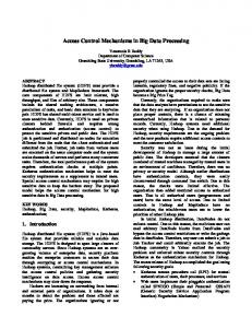
Array Indexing The following examples show how two and three dimensional arrays are indexed, first element to last element. All array indices are 0 based. Two dimensions [3,4]
Publication 1756-RM005A-EN-E - March 2000
Three dimensions [2,3,2]
0
0
0
0
0
0
1
0
0
1
0
2
0
1
0
0
3
0
1
1
1
0
0
2
0
1
1
0
2
1
1
2
1
0
0
1
3
1
0
1
2
0
1
1
0
2
1
1
1
1
2
2
1
2
0
2
3
1
2
1
Logix5000 Data Access
13
CIP Service Errors In general, the CIP status is returned as follows: • good status • general error with no extended status: code
00 Where:
Means:
04
This general status code means that the IOI could not be deciphered. Either it was not formed correctly or the match tag does not exist
05
The particular item referenced (usually instance) could not be found
06
The amount of data requested would not fit into the response buffer. Partial data transfer has occurred.
0A
An error has occurred trying to process one of the attributes
13
Not enough command data / parameters were supplied in the command to execute the service requested
1C
An insufficient number of attributes were provided compared to the attribute count
26
The IOI word length did not match the amount of IOI which was processed
00
SUCCESS!!
• error with extended status: code
01
extended
Where:
code
Means:
FF 01
05
21
You have tried to access beyond the end of the data object
FF 01
07
21
The abbreviated type does not match the data type of the data object.
FF 01
04
21
The beginning offset was beyond the end of the template
Publication 1756-RM005A-EN-E - March 2000
14
Logix5000 Data Access
CIP Read Data Service The CIP read data service reads a block of data starting from the specified address at the IOI string: • Any data which fits into the reply packet is returned, even if it does not all fit. • If all the data does not fit into the packet, an error is returned along with the data.
Command format Service code 4C
IOI string
size
where: size is the number of elements that you wish to read (16 bits).
Reply format Service code CC
00
status
abbreviated type
data
Read Data Fragmented Format Service This service reads more data than will fit into one packet: • The application must fragment the data into appropriately sized chunks. • The client process must then request the next piece of data, in turn. • The only parameter that changes from one request to the next is the byte offset (32 bits, least-significant bit first). • With each packet except the last, a size error is returned.
Command format Service code 52H
IOI string
size
byte offset
where: size is the number of elements that you wish to read (16 bits).
Publication 1756-RM005A-EN-E - March 2000
Logix5000 Data Access
15
Reply format Service code D2H
00
status
abbreviated type
data
CIP Write Data Service The CIP write data service writes a block of data starting from the specified address at the IOI string. The data type must match exactly for the write to occur.
Command format Service code 4D
IOI
abbreviated type
size
data
Reply format Service code CD
00
status
Write Data Fragmented Format Service This service writes more data than will fit into one packet: • The application must fragment the data into appropriately sized chunks. • The client process must then send the next piece of data, in turn. • The only parameter that changes from one write to the next is the byte offset (32 bits, least-significant bit first).
Command format Service code 53H
IOI
abbreviated type
size
byte offset
data
Reply format Service code D3H
00
status
Publication 1756-RM005A-EN-E - March 2000
16
Logix5000 Data Access
Multi-Request Service The Must-Request service packs more than one request into a packet. Use this service to optimize CIP reads and writes. Reading or writing one tag at a time can be quite time consuming. Most of the time is spent getting the message to the controller and back again, rather than any significant processing time at either end.
Command format 0A
02
20
02
offset #1
offset #2
…
service #1
24 service #2
01
count
…
service #n
where: count is a two byte field of the number of services to perform. offset #n is a two byte field which gives the byte offset (from the count field) to where the nth service starts. service #n is one of the services to executed. Example formats for CIP reads and writes are shown above. At all times the services and all other header information must fit within the boundaries of a packet.
Reply format 8A offset #2
00
Gen STS
00
count
offset #1
…
reply #1
reply #2
…
reply #n
where: count is a two byte field of the number of replies in the response. offset #n is a two byte field which gives the byte offset (from the count field) to where the nth reply starts. reply #n is the reply to the nth service in the request and follows the reply formats shown above for CIP reads and writes. All services are always processed. Each reply holds the status for its own service. The Gen STS byte indicates that an error occurred somewhere in the processing of the services.
Publication 1756-RM005A-EN-E - March 2000
Logix5000 Data Access
17
Get Attributes List Service This service returns the important information about a template: • • • •
structure size number of bytes number of members handle
Multiple reads may be required to get all of the template data.
Command format 03
03
20
6C
25
00
tt
tt
04
00
04
00
03
00
02
00
01
00
where: tt tt is the instance number of the template that you are reading, low byte first
Reply format 83
00
00
00
04
00
04
00
00
00
ss
ss
ss
ss
03
00
00
00
bb
bb
02
00
00
00
mm
mm
01
00
00
00
hh
hh
where: ss ss ss ss is the size of the template structure in 32 bit words. bb bb is the number of bytes that the structure takes up in memory. mm mm is the number of members in the structure. hh hh is the handle of the structure to be used in communications.
Publication 1756-RM005A-EN-E - March 2000
18
Logix5000 Data Access
Read Template Service This service returns the information contained within a template about each member’s type and where it appears in the structure (byte offset). Many reads may be required to get all of the template data.
Command format 4C
03
20
6C
25
00
tt
tt
rr
rr
rr
rr
bb
bb
where: tt tt is the instance number of the template that you are reading, low byte first rr rr rr rr is the byte offset to where to start reading. The first byte to read is offset 0. bb bb is the number of bytes to read.
Reply format CC
Publication 1756-RM005A-EN-E - March 2000
00
00
00
data
Logix5000 Data Access
Addressing Examples
19
The following examples show IOI strings for various data accesses: • In the IOI strings, the first byte is always the word count value. • In some cases, a PCCC logical ASCII form is also shown (presumes file mapping). The examples are grouped into the following sections: • Access Atomic and Pre-Defined Data Types, on page 19 • Access User-Defined Structures, on page 20
Access Atomic and Pre-Defined Data Types The following examples access tags that use either an atomic or pre-defined data type. To access:
This entry is specified:
single integer tag named “parts”
IOI string
04 91 05 70 61 72 74 73 00
PCCC symbolic
“parts”
6th element of an array of REALs named “setpoints”
IOI string
07 91 09 73 65 74 70 6f 69 7e 74 73 00 28 05
PCCC ASCII
$F8:6
PCCC symbolic
“setpoints[6]”
IOI string
09 91 07 70 72 6f 66 69 6c 65 00 28 02 28 05 29 00 01 01
PCCC ASCII
$N7:2:5:257
PCCC symbolic
“profile[2,5,257]”
single timer tag named “dwell3”
IOI string
04 91 06 64 77 65 6c 6c 33
PCCC symbolic
“dwell3”
two dimensional array of counters [5,0] named “counts”
IOI string
06 91 06 63 6f 75 6e 74 73 28 05 28 00
PCCC ASCII
$C5:5:0
PCCC symbolic
“counts[5,0]
IOI string
07 91 06 64 77 65 6c 6c 33 91 03 61 63 63 00
Append the “acc” string to the IOI as another symbolic segment.
PCCC ASCII
$T4:0:2
“.ACC” does not work.
IOI string
09 91 06 63 6f 75 6e 74 73 28 05 28 00 91 03 70 72 65 00
PCCC ASCII
$C5:5:0:1
single integer [2,5,257] of a three dimensional array named “profile”
accumulated value of a timer named “dwell3”
preset value of a two dimensional array of counters [5,0] named “counts”
Notes:
Returns 12 bytes of data. Requires last dimension with a value of 0.
“.PRE” does not work.
Publication 1756-RM005A-EN-E - March 2000
20
Logix5000 Data Access
Access User-Defined Structures The next set of examples access the following user-defined structures:
Structure name: STRUCT_A
Structure name: STRUCT_B
Member:
Data type:
Member:
Data type:
limit4
Bit
pilot_on
Bit
limit7
Bit
hourlyCount
INT[12]
travel
DINT
rate
REAL
errors
DINT
wear
REAL
Structure name: STRUCT_C
Structure name: STRUCT_D
Member:
Data type:
Member:
Data type:
hours_full
Bit
myint
INT
today
STRUCT_B
myfloat
REAL
sampleTime
TIMER
myarray
STRUCT_C[8]
shipped
COUNTER
mypid
PID
To access:
This IOI string is specified:
singular STRUCT_A tag “struct1”
05 91 07 73 74 72 75 63 74 31 00
“wear” member inside the singular STRUCT_A structure “struct1”
08 91 07 73 74 72 75 63 74 31 00 91 04 77 65 61 72
“travel” member inside a single dimensioned[9] array of STRUCT_A structure “str1Array”
0B 91 09 73 74 72 31 41 72 72 61 79 00 28 09 91 06 74 72 61 76 65 6c
5th “hourlyCount” element of a single STRUCT_B structure “struct2”
0D 91 07 73 74 72 75 63 74 32 00 91 0B 68 6f 75 72 6c 79 43 6f 75 6e 74 00 28 05
“rate” member of STRUCT_B inside STRUCT_C “struct3”
0C 91 07 73 74 72 75 63 74 33 00 91 05 74 6f 64 61 79 00 91 04 72 61 74 65
STRUCT_D is created with two dimensions “my2Dstruct4” the TIMER of the 4th STRUCT_C within the STRUCT_D “my2Dstruct4” element [4,5]
15 91 0B 6d 79 32 44 73 74 72 75 63 74 34 00 28 04 28 05 91 07 6d 79 61 72 72 61 79 00 28 04 91 0A 73 61 6d 70 6c 65 54 69 6d 65
3rd integer of “hourlyCount” member of STRUCT_B inside the 6th “myarray” member of STRUCT_C of the 2 dimensional array of STRUCT_D “my2Dstruct4” element [3,2]
1B 91 0B 6d 79 32 44 73 74 72 75 63 74 34 00 28 03 28 02 91 07 6d 79 61 72 72 61 79 00 28 06 91 05 74 6f 64 61 79 00 91 0B 68 6f 75 72 6c 79 43 6f 75 6e 74 00 28 03
Publication 1756-RM005A-EN-E - March 2000
Logix5000 Data Access
PLC-2 Commands
21
Use the PLC-2 commands to access one tag (only one tag) in a Logix5000 controller. In addition to sending the command, you must also map the message to an INT (16 bit integer) tag in the Logix5000 controller. Refer to “Appendix A: Map an Address” on page 33. Logix5000 controllers support the following PLC-2 commands: • • • • •
Unprotected Read Protected Write Unprotected Write Protected Bit Write Unprotected Bit Write
Unprotected Read This command provides the read capability for the PLC-2 commands.
Command format CMD
STS
TNS
TNS
address
offset
size
where: address offset must be on a 16 bit boundary. size must be an even number of bytes.
Reply format CMD
STS
TNS
TNS
data
where: data is up to 244 bytes.
Publication 1756-RM005A-EN-E - March 2000
22
Logix5000 Data Access
Protected Write This command provides a protected write capability for the PLC-2 commands.
Command format CMD
STS
TNS
TNS
address
offset
data
Reply format CMD
STS
TNS
TNS
Unprotected Write This command provides a basic write capability for the PLC-2 commands
Command format CMD
STS
TNS
TNS
address
offset
data
Reply format CMD
STS
TNS
TNS
Protected Bit Write This command provides a protected bit write capability for the PLC-2 commands.
Command format ← repeatable up to 61 times → CMD 02
Publication 1756-RM005A-EN-E - March 2000
STS
TNS
TNS
PLC-2 address
set mask
reset mask
Logix5000 Data Access
23
where: PLC-2 address is the typical two byte offset. set mask is one byte. reset mask is one byte.
Reply format CMD 42
STS
TNS
TNS
Unprotected Bit Write This command provides a bit write capability for the PLC-2 commands.
Command format ← repeatable up to 61 times → CMD 05
STS
TNS
TNS
PLC-2 address
set mask
reset mask
where: PLC-2 address is the typical two byte offset. set mask is one byte. reset mask is one byte.
Reply format CMD 45
STS
TNS
TNS
Publication 1756-RM005A-EN-E - March 2000
24
Logix5000 Data Access
PLC-5 Commands
Each PLC-5 command requires a system address in one of the following forms: • logical binary or logical ASCII, which addresses data by “file,” “element,” etc: – The first level of the logical binary must always be 0. This is required to access controller-scoped tags. – The second level is the “file” number. This is also the level following the letter(s) in the logical ASCII form. – The next 1, 2, or 3 levels correspond to the array dimension indices as follows: data[1][2][3]. – Any subsequent levels of logical address access parts of the complex types. Refer to “CIP Data Types” on page 6. Refer to “Appendix A: Map an Address” on page 33. • symbolic, which addresses data directly by a tag name: – The symbol string starts with a NULL character and ends with a NULL character. – In the simplest case, the symbol string consists of just the tag name. – To address an array, delimit the array indices with square brackets. The following examples depict symbolic addresses. EXAMPLE
Symbolic addresses • • • •
tag_name tag_name[x] tag_name[x,y,z] tag_name[x][y][z]
Logix5000 controllers support the following PLC-5 commands: • • • • • • •
Publication 1756-RM005A-EN-E - March 2000
Read Modify Write Read Modify Write N Typed Read Typed Write Word Range Read Word Range Write Bit Write
Logix5000 Data Access
25
For the typed read and typed write commands, you can only access the following data types:
IMPORTANT
• • • •
SINT INT DINT REAL
Read Modify Write The PLC-5 system address field specifies the word that is to be modified. Each PLC-5 system address is followed by an AND mask field and an OR mask field (two bytes each, low byte first). You can use more than one of these sets of fields to specify more than one word to modify. For each three field sequence (address, AND mask, OR mask), perform the following procedure: 1. Copy the specified word. 2. Reset the bits specified in the AND mask. 3. Set the bits specified in the OR mask. 4. Write the word back.
Command format
CMD 0F
STS
TNS
TNS
FNC 26
←
Repeatable up to 243 bytes
PLC-5 system address
AND
mask
OR
→ mask
where: AND mask specifies which bits in the word to reset (0). OR mask specifies which bits in the word to set (1).
Publication 1756-RM005A-EN-E - March 2000
26
Logix5000 Data Access
Reply format CMD 4F
STS
TNS
TNS
EXT STS
Read Modify Write N The PLC-5 system address specifies which word will be modified. A length field follows each address. Valid lengths are 2 bytes and 4 bytes. The AND mask and the OR mask follow the length field, respectively. These four fields can be repeated up to a length of 243 bytes. For each four field sequence (address, mask length, AND mask, OR mask), perform the following procedure: 1. Copy the specified word 2. Reset the bits specified in the AND mask 3. Set the bits specified in the OR mask 4. Write the word back
Command format ← Repeatable up to 243 bytes → CMD 0F
STS
TNS
TNS
FNC 79
no. of sets
PLC-5 system address
mask length
AND mask
where: AND mask specifies which bits in the word to reset (0). OR mask specifies which bits in the word to set (1).
Reply format Repeatable for each set, high word if necessary EXT STS
Publication 1756-RM005A-EN-E - March 2000
Reply
OR mask
Logix5000 Data Access
27
Typed Read The typed read command reads a block of data from the controller starting at the PLC-5 system address plus the packet offset.
Command format CMD 0F
STS
TNS
TNS
FNC 68
packet
offset
total
transaction
PLC-5 system addr
size
where: size is the number of elements to read.
Reply format: CMD 4F
STS
TNS
TNS
a
b
where: a indicates the type information or extended status if the command errors. b is the data bytes.
Typed Write The typed write command writes a block of data to the controller starting at the PLC-5 system address plus the packet offset.
Command format CMD 0F
STS
TNS
TNS
FNC 67
packet
offset
total
transaction
PLC5 sys addr
a
b
where: packet offset is in number of elements. total transaction is in number of elements. a indicates how many elements to write.
Publication 1756-RM005A-EN-E - March 2000
28
Logix5000 Data Access
b is the data byte.
Reply format Extended status exists only if there is an error CMD 4F
STS
TNS
TNS
EXT STS
Word Range Read The word range read command reads a block of words from the controller starting at the PLC-5 system address plus the word offset.
Command format CMD 0F
STS
TNS
TNS
FNC 01
packet
offset
total
transaction
PLC-5 system addr
where: packet offset is in numbers of 16 bit words.
total transaction is in numbers of 16 bit words. size is in number of bytes and must be even in number.
Reply Format CMD 0F
STS
where: data is up to 244 bytes.
Publication 1756-RM005A-EN-E - March 2000
TNS
TNS
data
size
Logix5000 Data Access
29
Word Range Write The word range write command will write a block of words from the controller starting at the PLC-5 system address plus the word offset.
Command format CMD 0F
STS
TNS
TNS
FNC 00
packet
offset
total
trans-act PLC-5 ion system addr
data
where: packet offset is in numbers of 16 bit words.
total transaction is in numbers of 16 bit words.
Reply format CMD 4F
STS
TNS
TNS
EXT STS
Bit Write This command will set and reset bits in a single word specified by the PLC-5 logical address. It can only change a single word in any given command.
Command format CMD 0F
STS
TNS
TNS
FNC 02
PLC-5 system address
set
mask
reset
mask
Reply format CMD 4F
STS
TNS
TNS
EXT STS
Publication 1756-RM005A-EN-E - March 2000
30
Logix5000 Data Access
SLC Commands
The SLC commands use strictly a logical form of addressing (i.e. file / element / sub-element). Refer to “Appendix A: Map an Address” on page 33. SLC logical addressing has a limited number of logical address levels so there are some special concerns: In a:
The element number is used as the:
one-dimension array
dimension index for addressing (data[elem])
two-dimensional array
index of the second dimension and the first dimension index is always 0 (data[0][elem]
three-dimensional array
index of the third dimension and the first and second dimension indices are both 0 (data[0][0][elem])
The following restrictions apply: • You can only use the SLC file types. For SLC type information, refer to the DF1 Protocol and Command Set Reference Manual, publication 1770-6.5.16. • For the typed read and typed write commands, you can only access the following data types: – SINT – INT – DINT – REAL Logix5000 controllers support the following SLC commands: • • • •
Publication 1756-RM005A-EN-E - March 2000
SLC SLC SLC SLC
Protected Protected Protected Protected
Typed Typed Typed Typed
Logical Logical Logical Logical
Read with 3 Address Fields Write with 3 Address Fields Read with 2 Address Fields Write with 2 Address Fields
Logix5000 Data Access
31
SLC Protected Typed Logical Read with 3 Address Fields The service is supported for compatibility with SLC modules.
Command format CMD 0F
STS
TNS
TNS
FNC A2
byte size
file number
file type
element number
EXT STS
data
subelement number
Reply format CMD 4F
STS
TNS
TNS
SLC Protected Typed Logical Write with 3 Address Fields This service is supported for compatibility with older modules.
Command format CMD 0F
STS
TNS
TNS
FNC AA
byte size
file num
file type
elem num
subelem num
data
Reply format CMD 4F
STS
TNS
TNS
EXT STS
Publication 1756-RM005A-EN-E - March 2000
32
Logix5000 Data Access
SLC Protected Typed Logical Read with 2 Address Fields This read command provides a simpler version for reading data.
Command format CMD 0F
STS
TNS
TNS
FNC A1
byte size
file number
file type
element number
Reply format CMD 4F
STS
TNS
TNS
EXT STS
data
SLC Protected Typed Logical Write with 2 Address Fields This write command provides a simpler version for writing data.
Command format CMD 0F
STS
TNS
TNS
FNC A9
byte size
file num
file type
Reply format CMD 4F
Publication 1756-RM005A-EN-E - March 2000
STS
TNS
TNS
EXT STS
elem num
data
Logix5000 Data Access
Appendix A: Map an Address
33
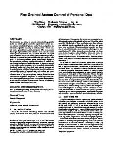
To access data in a Logix5000 controller using PLC or SLC commands, you must map files to tags: • You only have to map the file numbers that are used in messages; the other file numbers do not need to be mapped. • The mapping table is loaded into the controller and is used whenever a “logical” address accesses data. • You can only access controller-scoped tags (global data). To map an address: 1. In RSLogix 5000 software, open the project file for the controller whose data you want to access. 2. From the Logic menu, select Map PLC/SLC Messages.
3.a. 3.b.
4. 42260
3. For each file that is referenced in a PLC-5 or SLC command, make a map entry: a. Type the file number of the logical address. b. Type or select the controller-scoped (global) tag that supplies or receives data for the file number. (You can map multiple files to the same tag.) 4. For PLC-2 commands, specify the tag that supplies or receives the data. 5. Click OK.
Publication 1756-RM005A-EN-E - March 2000
34
Logix5000 Data Access
Notes:
Publication 1756-RM005A-EN-E - March 2000
Allen-Bradley Publication Problem Report If you find a problem with our documentation, please complete and return this form.
Pub. Title/Type
Logix5000 Data Access Reference Manual
Cat. No.
1756-L1, -L1Mx
Check Problem(s) Type:
Pub. No.
1756-RM005A-EN-E
Pub. Date
March 2000
Describe Problem(s)
Part No.
957259-71
Internal Use Only
Technical Accuracy
text
Completeness
procedure/step
illustration
definition
info in manual
example
guideline
feature
(accessibility)
explanation
other
What information is missing?
illustration
info not in manual
Clarity What is unclear?
Sequence What is not in the right order?
Other Comments Use back for more comments.
Your Name
Location/Phone
Return to: Marketing Communications, Allen-Bradley., 1 Allen-Bradley Drive, Mayfield Hts., OH 44124-6118Phone:(440) 646-3176 FAX:(440) 646-4320
Publication ICCG-5.21- August 1995
PN 955107-82
PLEASE FASTEN HERE (DO NOT STAPLE)
PLEASE FOLD HERE
NO POSTAGE NECESSARY IF MAILED IN THE UNITED STATES
BUSINESS REPLY MAIL FIRST-CLASS MAIL PERMIT NO. 18235 CLEVELAND OH POSTAGE WILL BE PAID BY THE ADDRESSEE
1 ALLEN-BRADLEY DR MAYFIELD HEIGHTS OH 44124-9705
PLEASE REMOVE
Other Comments
Back Cover
Publication 1756-RM005A-EN-E - March 2000 38 Supersedes Publication -
PN 957259-71 © 2000 Rockwell International Corporation. Printed in the U.S.A.