LOW BIT RATE VIDEO CODING USING. VARIABLE BLOCK SIZE MODEL. Y.B.Yu M.H.Chan A.G.Constantinides. Department of Electrical Engineering. Imperial ...
L O W BIT RATE VIDEO CODING USING VARIABLE BLOCK SIZE M O D E L Y.B.Yu
M.H.Chan
M8.3
A.G.Constantinides
Department of Electrical Engineering Imperial College of Science, Technology and Medicine London, SW7 2BT, ENGLAND
ABSTRACT In this paper, a new video coding algorithm is presented based on a variable block size image description model. The proposed algorithm operates in two steps: Firstly, it divides dynamically the image into blocks of variable size in such a way that large areas in the image consisting of two or more objects moving in different ways are described by small blocks, so that the assumption of uniform motion is valid for all blocks. The block size in those areas that cannot be motion compensated is decided by the content of image data. In the second step of the algorithm, motion compensation and transform coding are applied to these blocks of different sizes. Under the target rate of 64kbit/s the scheme can produce reconstruction images of reasonably high quality. Significant improvements can be observed using the proposed scheme.
1. Introduction Based on the concept of Frequency Division Multiplexing (FDM), the 2 B + D t channel structure is introduced to ISDN as the basic interface and nB + D as the primary rate interfaces, where n is an integer [l]. Evidently, it is desirable to devise video coding algorithms to work at the bit rates of B or n B , matching the channels capacity. As a result, 64 k bit/s video coding is becoming the focal point of image coding research. The CCITT has proposed the specifications for videophony and videoconferencing [ 2 , 3 ] , the generic structure being a block-based DCT and Motion Compensation coding algorithm.
In this paper, a new video coding algorithm based on a variable block size image description model is presented. The proposed algorithm divides the image into blocks of variable size, overcoming shortcomings of the fixed blocksize approach mentioned above. In contrast to the fixed block schemes, the philosophy of the proposed algorithm is to use blocksize as a further means to track the fluctuations of the image signal. Computer simulations have shown that a variable scheme is superior to those based on block of fixed size. In the next section, the concept of Variable Block Size Motion Compensation (VBSMC) and Variable Block Size Transform Coding (VBSTC) is outlined by example. Subsequently, the algorithms using variable blocksize are presented in detail, working at 64 kbit/s. Finally, simulation results and comparisons are presented.
2. Variable Block Size Motion Compensation and Transform Coding With respect to the motion estimation and compensation, the blocks can be specifically divided into three categories:
However, in those traditional block based video coding schemes, the image is partitioned into blocks of the same size. Motion estimation, compensation and subsequent coding operations are all conducted on these blocks. These schemes bear an implicit assumption that the motion vectors and other signal characteristics within each block are uniform. In order to maintain the validity of uniform motion within each block, relatively small blocks, such as 8 x 8 or 16x 16, are used in practice. The number of blocks and hence the number of motion vectors that have to be transmitted increases, resulting in low coding
t
efficiency particularly when large areas of uniform motion are present. An additional drawback to fixed partitioning of the image is the nonstationary characteristics of the motion compensated errors or image data. It is commonplace for compensated error signals or original image data to be encoded by transform methods. In low activity or highly correlated regions of an image, larger block sizes are preferred, whereas highly active or less correlated regions require smaller block sizes for accurate encoding. The fixed block size schemes, therefore, cannot achieve perfect adaptation. In general, the philosophy of fixed block size schemes is to fix blocksize but vary the number of bits allocated to each block in order to follow the nonstationarity of the image signal.
(1) blocks for which motion can be well compensated, including typical MC (Motion Compensated) blocks and FR (Frame Replenished) blocks; (2) blocks undergoing deformatory motion such as a block consisting of two or more objects moving at different velocities, or objects undergoing rotation, zooming or panning motion, the estimated motion vector will be inaccurate or even meaningless. This will result in poor motion compensation.
The B channel is a 64 k bit/s data transmission channel and the D channel an assistant channel, carrying signaling and possibly other packetised service.
(3) blocks in the uncovered region(s);
2229 CH2847-2/90/0000-2229 $1.00
'1990 IEEE
&--
&--- 1 m o t i h vecto)
i .........
j m o t i h vectdr
........
'.U..l< I:
; :
!....I{ i
.,...., : :: .: . .: ..... ........... ......... 1:
I
.........
I
I:
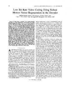
-+ (a) Big Blocksize
motion +tor
(c) Variable Blocksize
(b) Small Blocksize Figure 1. Variable Block Size Motion Compensation
This can be illustrated in Figure 1: Object A undergoes a translatory motion, so the blocks inside the object can be compensated with small distortion. The blocks in the background can also be compensated by use at the zero motion vector. These blocks can be considered to be in category one. Object B, however, undergoes deformatory motion, so the corresponding blocks may be reasonably compensated if the blocksize is small. These are the blocks in category Two. Block such as U, residing in the uncovered region, cannot be motion compensated and must be encoded by an intra-frame method. Such blocks fall into category three. The advantages of using variable blocksize are evident. For category one, the blocksize can be enlarged for efficient addressing of the motion vectors, making it superior to schemes based on small blocksize. Moreover, for category two, the blocksize can be small enough for effective compensation plus intra-frame coding, making it more effective than a large blocksize scheme. Finally, for category three the blocksize and position can be chosen in such a way that intra-frame coding can be efficiently applied. This is especially true immediately following a scene-cut, in which case pure intra-frame coding is most effective.
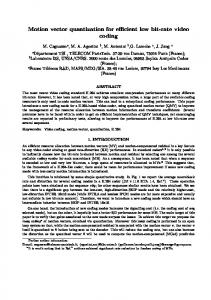
Figure 2. Variable Block Size Transform Coding
3. Complete Video Coding Scheme It is therefore very natural to combine these two approaches together to achieve even more efficient adaptation. The proposed algorithm works in two steps: Firstly, it divides the image into blocks of variable size dynamically, in such a way that large areas of the image consisting of two or more objects moving in different ways are described by small blocks, so that the assumption of uniform motion is valid for all blocks. In those areas that cannot be motion compensated, or in the scene-cut situation, the blocksize is decided by image content by using Varia'ble Block Size Transform model. In the second step, motion compensation and transform coding are applied to blocks of variable size.
Variable Blocksize Transform Coding [4] is designed to effect the adaptation by varying the position and size of the blocks rather than changing the coding parameters for different blocks of the same size. Figure 2 shows a partitioning of a typical frame from the sequence Miss America, together with the edge map. The criterion for the partitioning is to minimise the MSE (Mean Square Error) of the approximation over the given region. As can be observed, smaller blocks are allocated to regions of high activity. The algorithm has the ability to track the edges, matching the characteristics of the HVS (Human Vision System).
The partitioning methods can be many, but here the quadtree hierarchical data structure is adopted due to its efficiency of addressing. The number of bits required to represent a quadtree is [SI:
2230
where ~ ~ is the ~ final~ number ~ of segmented ~ ~ blocks. This can be reduced further by imposing minimum and maximum blocksizes in order to facilitate the subsequent transform coding operation. In our implementation, the maximum and minimum blocksizes are 32x32 and 8x8, respectively. The partitioning operation is also conducted in a hierarchical manner, and splitting is always performed on the most erroneous block. The error criterion is the SSE (Sum Square Error) after block classification:
1
Objectively, more than one dB improvement over the fixed block scheme can be observed using the proposed scheme. A plot of objective SNR (Signal to Noise Ratio) versus frame number is shown in Figure 4, SNR being defined as follows:
where S ( x , y ) and S^(x,y) are the original and reconstructed image signals, respectively. References: S. E. Minzer, “Broadband ISDN and Asynchronous Transfer Mode(ATM)”, IEEE Communication Magazine, , pp. 17-24 (September 1989).
where Sk(.) is the block data for the current frame and Sk-l(.) refers to the corresponding block in the previous
frame. The final effect is to spread the distortion uniformly over the whole image, guaranteeing the distortion contained in each block is roughly the same. Two criteria can be used to terminate splitting: One is to satisfy the maximum SSE of the block to a predefined threshold, thus controlling the reconstruction image quality. The other, also utilised in this research, is to limit the total number of blocks, thus controlling the overall bit rate.
CCITT, “Specifications for Reference Model version 2 (RM2)”, SG XV. Specialists Group on Codingfor Visual Telephony, Doc. 141 (Sep. 1986). CCITT, “Description of Reference Model 6 (RM6)”, SG XV. Specialists Group on Coding for Visual Telephony, Doc. 396 (Oct. 1988). Y.B. Yu and A.G. Constantinides, “Variable Block Size and Position Transform Coding”, Fourth European Signal Processing Conference, Grenoble, France (1988 Sept.).
Motion Estimation is carried out through the coarseand-fine 3 step search algorithm [6]. Since the block can be small to enable accurate compensation, loop filtering is not required. The standard DCT is used, zig-zag scanning and 2-D VLC (Variable Length Code) being applied to the coefficients. When the larger block is encountered only the first 64 coefficients are encoded. The rest of them are simply eliminated to constrain the number of bits assigned to these blocks. Buffer control is based on the groups of blocks and implemented through variation of a threshold applied to the coefficients. For more details, please refer to [3] and [7]
Y. Cohen, M.S. Landy, and M. Pavel, “Hierarchical Coding of Binary Images”, IEEE Trans. Pattern Anal. Machine Intell., Vol. PAMI7 , pp. 284-298 (May 1985). J.R. Jain and A.K. Jain, “Displacement Measurement and Its Application in Interframe Image Coding”, IEEE Trans. on Commun., Vol. COM-28, pp. 1799-1808 (1981). Y.B. Yu, “Transform Coding of Images based on Shape Adaptive Models”, Ph. D Thesis, Imperial College, University of London, Lodon (1989).
4. Simulation Results
Simulations have been conducted to assess the effectiveness of the proposed algorithm. AT the target rate of 64kbitis the scheme works on the image size of one quarter CSIF (Common Source Input Format), and can produce reconstruction images of high quality. For comparison purposes the CCITT’s (reference model 6) coding algorithm, based on blocks of two different but fixed sizes for coding and for motion compensation respectively [3], has also been simulated. Typical reconstructions and partitioning are shown in Figure 3. Loop filtering is stripped off so that the proposed scheme produces sharper and clearer images than that of the CCITT algorithm.
2231
(a)Original Image from Sequence Miss America
(b)Variable Block Size Partitioning
(c)Coded Image by RM6
(d)Coded Image by Proposed Scheme
Figure 3. Typical Reconstructions of Proposed Scheme and RM6 25 dB
24
23 22
'
21
z 20 19
18
Reference Model 6
17
l60
20
40
60
80
IO0
Figure 4. SNR Performances of Proposed Scheme and RM6
2232
I20