Low Complexity Adaptive Turbo Space-Frequency Equalization for. Single-Carrier Multiple-Input Multiple-Output Systems. Ye Wu, Student Member, IEEE, ...
2050
IEEE TRANSACTIONS ON WIRELESS COMMUNICATIONS, VOL. 7, NO. 6, JUNE 2008
Low Complexity Adaptive Turbo Space-Frequency Equalization for Single-Carrier Multiple-Input Multiple-Output Systems Ye Wu, Student Member, IEEE, Xu Zhu, Member, IEEE, and Asoke K. Nandi, Senior Member, IEEE
Abstract—By combining single-carrier (SC) frequency domain equalization (FDE) and Turbo equalization, we propose a minimum mean square error (MMSE) based block-wise low complexity Turbo space-frequency equalization (TSFE) structure, which offers a tremendous complexity reduction over the symbol-wise TSFE and Turbo time-domain equalization (TTDE) structures. With a moderate code rate, the proposed SC TSFE significantly outperforms its Turbo OFDM (TOFDM) counterpart, at a comparable complexity. Besides, TSFE based on the least-mean-square structured channel estimation (LMS-SCE) provides a performance close to the case with perfect channel state information (CSI), at a high convergence rate. Index Terms—Multiple-input multiple-output (MIMO), frequency domain equalization (FDE), Turbo equalization, orthogonal frequency division multiplexing (OFDM), adaptive channel estimation.
I. I NTRODUCTION
F
REQUENCY domain equalization (FDE) [1]–[3] for single carrier (SC) block transmission has been shown to be effective for frequency selective fading channels. Compared to time-domain equalization such as decision feedback equalization (DFE) [4] and maximum likelihood sequence estimation (MLSE) [5], FDE requires less complexity to achieve the same performance, especially in highly dispersive channels [2]. Compared to orthogonal frequency division multiplexing (OFDM) for multicarrier (MC) block transmission, SC-FDE has lower peak-to-average power ratio and less sensitivity to carrier synchronization [1]. In [6], linear FDE was employed in multiple-input multiple-output (MIMO) systems. A layered space-frequency equalization structure was proposed in [7] for MIMO systems, which provides enhanced performance over the single-layer MIMO FDE in [6] by combining FDE with successive interference cancellation. However, [6] and [7] only assumed quasi-static channels. Turbo (iterative) equalization [8] has been demonstrated to be another effective solution for frequency selective fading channels, incorporating both equalization and decoding. Originally inspired by the Turbo codes [9], Turbo equalization in [8] employed the maximum a posteriori probability (MAP) algorithm. To reduce the complexity, an MMSE based suboptimum Turbo equalizer was proposed using the so-called ‘average variance’ technique (i.e., the variance of each symbol Manuscript received January 24, 2007; revised May 15, 2007; accepted July 22, 2007. The associate editor coordinating the review of this paper and approving it for publication was A. Grant. This work was supported by the Overseas Research Students Award Scheme (ORSAS). The authors are with the Group for Signal Processing, Department of Electrical Engineering and Electronics, The University of Liverpool, Liverpool, U.K. (e-mail: {ye.wu, xuzhu}@liv.ac.uk). Digital Object Identifier 10.1109/TWC.2008.070095.
is replaced by the time average of all the variances) in [10]– [12], whose coefficients remain unchanged within a data block. Single-input single-output (SISO) Turbo equalization in [10] was extended to the MIMO case [13], which is referred to as Turbo time-domain equalization (TTDE) here. However, most previous work on Turbo equalization assumed time-domain processing, which introduces a huge complexity with a large number of antennas and a high channel delay spread. In this letter, we propose an MMSE based low complexity adaptive Turbo space-frequency equalization (TSFE) structure for SC MIMO systems with block transmission, combining the advantages of Turbo equalization and block processing for SC-FDE. Our work is different in that we derive the equalizer coefficients in the frequency domain. This is a novel and effective application of the ‘average variance’ technique [10]–[12] for MIMO SC-FDE systems, which allows channel equalization on each independent frequency bin. As a result, a new concise block-wise FDE structure is proposed and the computational complexity is significantly reduced. We also investigate adaptive channel estimation for time-varying channels, which are correlated between adjacent blocks due to Doppler effect. This issue was not considered in the previous work on Turbo equalization for SC block transmission [10]. It is shown that the proposed block-wise low complexity TSFE introduces a tremendous complexity reduction over the symbol-wise TSFE as well as TTDE for SC MIMO systems. In terms of performance, the low complexity TSFE is close to the symbol-wise TSFE and superior over TTDE over highly dispersive channels, achieving the same bandwidth efficiency. With a moderate code rate, SC TSFE also significantly outperforms its TOFDM [13] counterpart for MC block transmission, at a comparable complexity. An intensive performance analysis is provided for the low complexity TSFE, compared to TOFDM [13]. Besides, we incorporate the low complexity TSFE with a so-called least-mean-square structured channel estimation (LMS-SCE) method [14] for time-varying channels. The LMS-SCE based TSFE structure utilizes the fading correlation between adjacent frequency bins and provides a bit error rate (BER) performance close to the case with perfect channel state information (CSI) even in the fast fading environment, with a low training overhead. In Section II, we present the system model. The TSFE structure is proposed in Section III. Section IV and V provide the performance analysis and complexity analysis, respectively. Simulation results are shown in Section VI, and the conclusion is drawn in Section VII. Let (.)T and (.)H denote the transpose and complexconjugate transpose of a matrix/vector, respectively. (.)∗ refers to the scalar complex-conjugate. E(X) and Cov(X, Y) =
c 2008 IEEE 1536-1276/08$25.00 �
IEEE TRANSACTIONS ON WIRELESS COMMUNICATIONS, VOL. 7, NO. 6, JUNE 2008
E(XY H )− E(X)E(YH ) respectively denote the expectation and covariance operators. Diagonal and block diagonal matrices are denoted by diag(.) and DIAG(.), respectively, with elements/matrices on the diagonal listed in the parentheses. Also define operators vec and mat as: �T � vec(a1 · · · aQ ) = aT1 · · · aTQ ⎤ ⎡ a1 0 · · · 0 ⎢ 0 a2 · · · 0 ⎥ ⎥ ⎢ mat(a1 · · · aQ ) = ⎢ . .. . . .. ⎥ ⎣ .. . . . ⎦ 0 0 · · · aQ where aq (q = 1, · · · , Q) denotes a vector.
2051
into the frequency domain by fast Fourier transform (FFT). The signal vector on the mth frequency bin is given by Xm =
x
=
hin dm−i n
(2)
m m where Xm , Hm denote the discrete Fourier n , Dn and N transforms (DFTs) of xm , hin , din and nm , respectively. At the receiver, the mean μin and variance vni of din are computed before equalization:
αp P (din = αp ) (3) μin = E(din ) = αp ∈S
vni = Cov(din , din ) =
|αp |2 P (din = αp ) − |μin |2
(4)
αp ∈S
We consider a MIMO system with Nt transmit antennas and Nr receive antennas, as depicted in Fig. 1. Assuming 2Q -ary modulation with M symbols per block per antenna, the information bit sequence b is encoded into an errorcorrecting code (ECC) sequence c = [c1 · · · cNt M ], where ct = [ct,1 · · ·ct,Q ] (t = 1, · · · , Nt M ) with ct,q ∈ {0, 1} (q = 1, · · · , Q) denoting the qth coded bit in ct . The code sequence c is then interleaved bit-levelly and passed on to the mod� ulator, which maps ct (t = 1, · · · , Nt M ) , the interleaved version of ct into the constellation in accordance with the 2Q -ary symbol alphabet S = {α1 , · · · , α2Q }, where symbol αp (p = 1, · · · , 2Q ) has a unit energy and a bit pattern sp = [sp,1 · · ·sp,Q ] with sp,q ∈ {0, 1} (q = 1, · · · , Q) denoting the qth bit in sp . Finally, the data sequence is multiplexed into Nt transmission blocks, each containing M symbols. Let din (i = 0, · · · , M − 1) denote the ith data symbol in a block transmitted by� the nth (n = 1, · · · , Nt ) antenna, � and cin = cin,1 · · ·cin,Q the bit pattern of din . The channels are assumed quasi-static during a certain block. The overall channel memory is assumed to be N , lumping the effects of the transmit filter, receive filter and physical channel. The received signals are sampled at symbol rate as in [1], [3], [7], since the focus of this letter is to show advantages of the low complexity TSFE over its TTDE and TOFDM counterparts. Similar trends for performance comparison can be found with oversampling employed. To implement SC-FDE block transmission, each data block is prepended with a cyclic prefix (CP), which is the replica of the last N symbols in the block. At the receiver, the CP is discarded to eliminate the interblock interference (IBI) and to make the received block appear to be periodic with period M . This produces the appearance of circular convolution, which is essential to the operation of fast Fourier transform (FFT) to significantly reduce the overall signal processing complexity [1], [3]. Define xm as the received signal vector at the mth sampling time within a block, which is given by Nt
N
m m Hm n Dn + N
n=1
II. S YSTEM M ODEL
m
Nt
+n
m
both of which depend on the log-likelihood ratio (LLR) LI (cin,q ), as computed in [10]. III. T URBO S PACE -F REQUENCY E QUALIZATION It has been shown that in highly dispersive channels, the block-wise frequency-domain filter is more effective than the time-domain filter with a similar complexity to mitigate the inter-symbol interference [7]. The iterative receiver with TSFE is depicted in the right part of Fig. 1, which consists of a soft-input soft-output equalizer using TSFE, a Gaussian LLR estimator [11], an ECC decoder and � an adaptive channel estimator. The equalizer output signals d˜in (n = 1, · · · , Nt ; i = 0, · · · , M − 1) are passed to the Gaussian LLR
� estimator for estimation of the extrinsic �LLRs LE (cin,q ) , which are obtained as in [10]. LE (cin,q ) are demultiplexed � and deinterleaved to the intrinsic LLRs LI (ct,q ) , and are then input to the decoder as its a priori information. Both the ˆ and the extrinsic LLRs estimate of�information bit sequence b
� LE (ct,q ) are generated by the decoder. LE (ct,q ) are � interleaved and multiplexed to the intrinsic LLRs LI (cin,q ) , and are then fed back to the equalizer for the next iteration. In this section, we start from the symbol-wise MMSE TSFE, and then propose its simplified version. A. Symbol-wise TSFE
� To detect substream dik (i = 0, · · · , M − 1) which is transmitted from the kth (k = 1, · · · , Nt ) antenna, the symbolwise MMSE TSFE employs a symbol-wise frequency-domain linear filter for each iteration. Let Wki,m (m = 0, · · · , M − 1) denote a size-L × 1 frequency-domain weight vector with respect to dik on the mth frequency bin, and bik denote the corresponding time-domain feedback coefficient. Letting Uik = vec(Wki,0 · · ·Wki,M−1 ) and X = mat(X0 · · ·XM−1 ), the equalizer output symbol d˜ik is given by d˜ik
(1)
=
n=1 i=0
where hin is the overall channel impulse response (CIR) with respect to dm−i , and nm denotes the additive white Gausn sian noise (AWGN) vector, whose elements have single-sided power spectral density N0 . The received signals are transferred
= where
M−1 1
Wi,m Xm ej2πmi/M + bik M m=0 k
1 i U Xf i + bik M k
�T � f i = ej2π0i/M · · ·ej2π(M−1)i/M
(5) (6)
2052
Fig. 1.
IEEE TRANSACTIONS ON WIRELESS COMMUNICATIONS, VOL. 7, NO. 6, JUNE 2008
Block diagram of the SC MIMO system with adaptive TSFE at the receiver.
In particular, f 0 is a vector of all unit elements. Furtherˆn = more, we define Dn = diag(Dn0 · · ·DnM−1 ), and H 0 M−1 m ˆ ˆ ˆ mat(Hn · · ·Hn ), where Hn (m = 0, · · · , M − 1) denotes the estimate of Hm n . The equalizer coefficients are derived based on the MMSE criterion, which minimizes the MSE cost function � �2 � � (7) Jki = E �d˜ik − dik � It can be derived that the linear weight vector Uik is expressed as −1 ˆ 0 Ωi H kf (8) Uik = i 1−vk ˆ H Ωi −1 H ˆ kf 0 1+ f 0H H M
1 M
�Nt �M−1
k
The frequency-domain linear filter weights of the symbolwise TSFE in subsection III-A are different for each symbol within a data block, and therefore requires a huge computational complexity. To reduce the computation burden, a direct and effective approach is to implement the block processing on each frequency bin independently, i.e., to make Uik independent of the time index i. This can be achieved by simply replacing vni (n = 1, · · · , Nt ; i = 0, · · · , M − 1) in (8) �M−1 1 by v n = M i=0 vni , which is the average of vni within a i reduces block [10]. Thus, � to a block diagonal matrix � Ω0 in (8)M−1 , where as Ω = DIAG R · · · R
m ˆ i−m i−m H ˆ H Hn f m=0 vn Hn f
where Ω = + N0 I. n=1 The corresponding feedback coefficient is given by � �N t 1 iH
i i ˆ Hn E(Dn ) f i U (9) bk = μk − M k n=1 � � where E(Dn ) = diag E(Dn0 )· · ·E(DnM−1 ) , with � M−1 i −j2πmi/M E(Dnm ) = (m = 0, · · · , M − 1) i=0 μn e denoting the DFT of μin . The resulting equalizer output d˜ik is: � � Nt
1 H i i ˆ n E(Dn ) f i U X− H d˜k = M k n=1 i
B. Low Complexity Block-wise TSFE
1 H ˆ kf 0 + μik Uik H (10) M which is illustrated by the equivalent block
�diagram in the upper part of Fig. 2. To detect substream dik (i = 0, · · · , M − 1) from the kth antenna, at a particular iteration the frequencydomain received signals are passed through a linear filter with weight vector Uik corresponding to dik . Channel equalization �
and interference suppression are performed using LI (cin,q ) from the previous iteration (LI (cin,q ) = 0 for all n, i, q for the first iteration). The frequency-domain equalized signals are then transferred into the time by multiplying � domain � the ith �Nt ˆ H Hn E(Dn ) by f i /M . X − n=1 output signal vector Uik H ˆ 1 i 0 μk Uik H Finally, a constant M k f is added to the ith output branch to remove the residual interference. The resulting MSE with respect to dik is given by 1 iH ˆ 0 U Hk f (11) M k The above procedure is repeated for substreams from different transmit antennas. Jki = 1 −
m
R
=
Nt
ˆm ˆ m + N0 I vn H n Hn H
(12)
n=1
As a result, Uik reduces to Uk = vec(Wk0 · · ·WkM−1 ), where −1
Wkm
as
=
1+
1−v k M
m ˆm H R k �M−1 mH m−1 m ˆ ˆ H H R m=0
k
(13)
k
The resulting equalizer output d˜ik in (10) can be expressed 1 H d˜ik = U M k
� X−
Nt
� ˆ n E(Dn ) f i H
n=1
1 i Hˆ 0 μ U Hk f (14) M k k This is depicted in the lower part of Fig. 2, which proposes a new block-wise linear frequency-domain filter, rather than the symbol-wise filter for the symbol-wise TSFE, is employed, as Uk is independent of the time index i. The frequency-domain equalized signals are transferred back into the time domain by inverse FFT (IFFT). Finally, a constant is added to the ith output branch to remove the residual interference. The resulting MSE with respect to dik also becomes independent of the time index i, expressed as −1 1 �M−1 ˆ mH m ˆm H k m=0 Hk R M Jk = 1 − (15) −1 � m M−1 ˆ mH 1−v k ˆm H H 1+ M R k m=0 k +
Similar to TOFDM [13], the frequency-domain linear filter weights of the block-wise TSFE are derived on each independent frequency bin. Thus, the block-wise TSFE requires a much lower complexity than the symbol-wise TSFE, as well
IEEE TRANSACTIONS ON WIRELESS COMMUNICATIONS, VOL. 7, NO. 6, JUNE 2008
2053
Fig. 2. Block diagrams of the symbol-wise TSFE and block-wise low complexity TSFE at a particular iteration for detection of substream 1, · · · , Nt ; i = 0, · · · , M − 1).
as TTDE [13] employing a time-domain filter to achieve a comparable performance to TSFE.
We provide intensive theoretical performance analysis of the proposed low complexity TSFE structure, whose performance approaches that of the symbol-wise TSFE, as can be shown in Section VI. As in [7], [15], we employ appropriate analytical performance bounds with given channel realizations. For simplicity, we only investigate the BER performance before decoding, as the overall performance is dominated by Turbo equalization instead of decoding with a relatively weak code such as the convolutional code (compared to the Turbo code) employed in this letter. The block indexes are ignored for the simplicity of expression. A. TSFE vs. TOFDM Let γk denote the equalizer output signal to interferenceand-noise ratio (SINR) with respect to the detected substream
i� dk (i = 0, · · · , M − 1) from the kth (k = 1, · · · , Nt ) transmit antenna at a particular iteration. For an unbiased MMSE filter [4], it can be shown that the output SINR is related to the MSE by γk = 1/Jk − 1. Without loss of generality, we assume QPSK modulation here. Thus, the corresponding BER √ can be approximated by BERk = Q( γk ) [16]. Using the Gaussian tail function and further approximations, the BER can be upperbounded by BERk ≤exp(−γk /2)/2 at a high SNR [17]. Therefore, the BER for TSFE is given by BERkT SF E
dk (k =
⎛ ⎞ �M−1 ˆ mH m−1 ˆ m 1 H H R 1 1 k ⎠ (16) ≤ exp⎝ · M� m=0 k m−1 2 2 vk M−1 H m ˆ mH R ˆ H −1 M
IV. P ERFORMANCE A NALYSIS
i�
m=0
k
k
It is of interest to compare the performance of TSFE and its TOFDM counterpart [13], assuming the same number of iterations and the same channel estimates. At a particular iteration, the output SINR with respect to the mth OFDM symbol (or subcarrier) transmitted by the kth antenna is given by γkm = 1/Jkm − 1. The average BER of OFDM with given channel realization is determined by averaging over all the symbols, which is bounded by: M−1 1
BERkm,T OF DM M m=0 � � M−1 ˆm ˆ mH Rm−1 H 1
1 H k k ≤ exp (17) · ˆ mH Rm−1 H ˆm−1 2M m=0 2 vkm H k k
BERkT OF DM =
Performance with a large number of iterations at a high SNR: With the increase of the number of iterations, μm k m approaches dm k , and therefore vk in (17) approaches zero at a high SNR, i.e., vk0 ∼ =vk1 ∼ = · · ·vkM−1 ∼ = 0, as can be testified by simulations. Thus, the BER of TOFDM can be approximated by � � M−1 1 ˆ mH m−1 ˆ m 1
exp − H R H (18) BERkT OF DM ∼ = k 2M m=0 2 k In this case, we have vn0 ∼ =vn1 ∼ = · · ·vnM−1 ∼ = vn ∼ = 0, m m ∼ which leads to R = R . Thus, the BER of TSFE can be approximated by � � M−1 1 � ˆ mH m−1 ˆ m � T SF E ∼ 1 Hk Hk R (19) BERk = exp − 2 2M m=0
2054
IEEE TRANSACTIONS ON WIRELESS COMMUNICATIONS, VOL. 7, NO. 6, JUNE 2008
TABLE I N OMALIZED C OMPLEXITY WITH Nt = Nr = 4, N = 6, P = 4, M = 64 ( FOR TSFE AND TOFDM)/M = 128( FOR TTDE) Receiver Low complexity TSFE Symbol-wise TSFE TOFDM [13] TTDE [13]
1 iteration 100% 100% 103% 478%
2 iterations 209% 2761400% 211% 1069%
5 iterations 536% 11045000% 532% 2844%
� � � � Using exp n1 ni=1 xi ≤ n1 ni=1 exp(xi )(xi ≤ 0, ∀i), it can be shown that the BER of TSFE with given channel realization is not higher than that of its TOFDM counterpart, with a large number of iterations. Thus, TSFE achieves a better average BER performance than TOFDM in frequency selective fading channels with the increase of the number of iterations. Comparing the output SINRs for TOFDM to that of TSFE, it suggests that less fluctuation of SINR is likely to yield a better average BER performance. B. Special Case: Flat Fading Channels In the flat fading environment (N =0), the channel frequency response Hm k (m = 0, · · · , M − 1) reduces to the CIR vector hk of size Nr × 1. Correspondingly, the BER for TOFDM is expressed as BERkT OF DM
� � M−1 ˆ H rm−1 h ˆk h 1
1 k · ≤ exp ˆ H rm−1 h ˆk − 1 2M m=0 2 vkm h k
(20)
ˆ k denotes the estimate of hk , and rm = where h �Nt m ˆ ˆH n=1 vn hn hn + N0 I. It can be derived that the BER of TSFE is given by � � ˆ H r−1 h ˆk 1 h 1 k · BERkT SF E ≤ exp (21) ˆ H r−1 h ˆk − 1 2 2 vkh k
�Nt
ˆ ˆH n=1 v n hn hn
where r = + N0 I. Performance with one iteration: At the first iteration particularly, the variance of each symbol for both TSFE and TOFDM is set to be unit, i.e., vn0 = vn1 = · · ·vnM−1 = 1. Hence, both TSFE and TOFDM reduce to a linear MMSE detector and provide exactly the same performance as: BERkT OF DM
= ≤
BERkT SF E � � ˆ H ˜r−1 h ˆk 1 h 1 k exp · ˆ H ˜r−1 h ˆk − 1 2 2 h
(22)
k
�Nt ˆ ˆ H hn hn + N0 I. where ˜r = n=1 Performance with a large number of iterations at a high SNR: With the increase of the number of iterations and at a high SNR, vn0 ∼ = vn1 ∼ = · · ·vnM−1 ∼ = v n approach zero. As a m result, r in (20) can be approximated by r in (21), and both (20) and (21) can be approximated by � � 1 ˆ H −1 ˆ 1 BERkT OF DM ∼ r h (23) = BERkT SF E ∼ = exp h k 2 2 k Hence, TSFE and TOFDM achieve similar performance with a large number of iterations at a high SNR in flat fading.
V. C OMPLEXITY A NALYSIS We investigate the complexity of the proposed TSFE, compared to that of TTDE and TOFDM. For simplicity, we focus on the complexity of Turbo equalization without considering decoding, which consists of four parts: 1) complexity of FFT/IFFT (for TSFE and TOFDM only); 2) complexity of calculating the equalizer coefficients; 3) complexity of equalization which denotes the signal processing required to generate the equalized symbols; and 4) complexity of calculating the statistics associated with the LLR, mean, and variance for each symbol. Solution of the equalizer coefficients plays a critical role in the whole complexity, for which TTDE requires approximately F 3 Nr3 /3 complex multiplications for matrix inversion, while both the low complexity TSFE and TOFDM need to find the inverses of M Nr × Nr matrices, each requiring approximately Nr3 /3 complex multiplications only. This implies the complexity similarity between the low complexity TSFE and TOFDM, as well as the complexity advantage of the low complexity TSFE over its TTDE counterpart (with a large filter length F ). A numerical example of the normalized overall complexity in terms of the number of complex multiplications is shown in Table I, with N t = 4 transmit antennas, N r = 4 receive antennas, QPSK modulation (P = 4), overall channel memory N = 6, and different numbers of iterations. TSFE and TOFDM have the same configuration with a block size of M = 64 symbols with a CP of length N , while TTDE has a block size of M = 128 symbols with total 2N redundant symbols, where N symbols eliminate IBI, and the other N symbols are used for the filtering purpose (i.e., the filter length F = N + 1). In this case, all the structures achieve the same spectral efficiency. The low complexity TSFE obviously requires a complexity comparable to that of TOFDM, much less than that of TTDE, especially with the increase of the number of iterations. Thanks to the block-wise processing, the low complexity TSFE with 5 iterations saves around 20000 times of complexity over the symbol-wise TSFE. VI. S IMULATION R ESULTS We choose a rate 1/2, memory 2 recursive systematic convolutional (RSC) encoder [9] with generator (1 + D + D2 , 1 + D2 ) to generate the ECC bits. We consider MIMO systems with the same configuration as Table I. The symbol rate is assumed to be 1.25 M-Baud, i.e., the symbol period is T = 0.8μs. The physical channel is modeled by following the exponential power delay profile [18] with a root mean squared (RMS) delay spread of σ. A default value of σ = 1.25T is used, except in Fig. 4. Both transmit and receive filters use a raised-cosine pulse with a roll-off factor of 0.35. TTDE has a filter decision delay Nd = 1, which is optimized using the scheme in [18]. The SNR is defined as the spatial average ratio of the received signal power to noise power. Figure. 3 demonstrates the average BER performance of the low complexity TSFE, compared to the symbol-wise TSFE, and its TOFDM and TTDE counterparts. It can be observed that the low complexity TSFE provides close performance to the symbol-wise TSFE, with a tremendous complexity (e.g., around 20000 times with 5 iterations). Thus, in the following,
IEEE TRANSACTIONS ON WIRELESS COMMUNICATIONS, VOL. 7, NO. 6, JUNE 2008
QPSK,Nt=4,Nr=4,N=6,σ=1.25T
0
QPSK,N =4,N =4,N=6,SNR=7dB t
0
10
r
10 Symbol−wise TSFE Low complexity TSFE TOFDM TTDE
1 iteration
−1
10
TSFE TOFDM TTDE
−2
10
2 iterations −3
10
5 iterations
−4
10
1 iteration
−1
10
average BER
average BER
2055
−2
10
2 iterations −3
10
−4
10
5 iterations −5
10
−5
4
5
6
7 SNR(dB)
8
9
10
10
Fig. 3. Performance of TSFE, TOFDM, and TTDE with Nt = Nr = 4, RMS delay of σ = 1.25T , and perfect CSI.
0
0.25
0.5
1.5
1.75
2
Fig. 4. Impact of the RMS delay spread on performance of TSFE, TOFDM, and TTDE with Nt = Nr = 4, SNR = 7 dB, and perfect CSI. QPSK,K=4,L=4,N=6,σ=1.25T
0
10
Perfect CSI LMS−SCE −1
10
1 iteration average BER
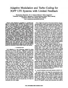
we focus on the low complexity TSFE which is denoted by TSFE for simplicity. Compared to TTDE, TSFE provides better performance at much lower complexity, though the performance gap decreases with the increase of the number of iterations. It can be explained that TSFE employs the whole observation block in its filter, which is much longer than the filter length of TTDE. The FDE based TSFE also outperforms TOFDM with a relatively large number of iterations. The performance gain with 5 iterations is over 1 dB at BER = 1e − 5. Figure. 4 shows the impact of the RMS delay spread on performance of TSFE, TOFDM and TTDE at a fixed SNR = 7 dB. The horizontal axis denotes the RMS delay spread normalized to the symbol period. With the same number of iterations, TSFE, TOFDM and TTDE achieve similar performance at a low RMS delay spread. With a relatively high delay spread, however, TSFE outperforms TOFDM and TTDE. This is because TSFE can capture the most multipath channel energy among all the three structures in highly dispersive channels. At a high RMS delay spread, TSFE also outperforms its flat fading case. With 5 iterations, the BER of TSFE at an RMS delay spread of σ = 2T is around 17 times lower than its BER for flat fading. While TOFDM remains a relatively stable performance over different RMS delay spreads, with a BER improvement of only 2 times at σ = 2T compared to the flat fading case with 5 iterations. Meanwhile, TTDE suffers from performance degradation in highly dispersive channels with. Finally, we incorporate TSFE with a so-called adaptive LMS structured channel estimation (LMS-SCE) [14] scheme for time-varying channels, utilizing the correlation between adjacent frequency bins. The channel estimates are updated based on the LMS criterion. It was shown in [14] that LMSSCE outperforms other adaptive channel estimation schemes based on the assumption of independent frequency bins, at a modest complexity and a high convergence speed. With each frame consisting of 20 training blocks and 300 data blocks (i.e., the training overhead is only 6.25%). Figure 5
0.75 1 1.25 Normalized RMS delay (σ/T)
−2
10
2 iterations
−3
10
5 iterations
−4
10
−5
10
4
5
6
7 SNR(dB)
8
9
10
Fig. 5. Performance of the LMS-SCE based TSFE with Nt = Nr = 4, RMS delay of σ = 1.25T , and fd T = 1/6250.
demonstrates the performance of TSFE with LMS-SCE at a relatively high Doppler frequency of fd = 200Hz (i.e., fd T = 1/6250), using a step size of μ = 3e − 5 for LMS updates. It is shown that there is a steady performance gap of around only 1 dB between the LMS-SCE based TSFE and the perfect CSI case over the SNR range of 7 ∼ 10 dB, which implies the effectiveness of the LMS-SCE based TSFE in the fast fading environment. VII. C ONCLUSION We have proposed a low complexity adaptive TSFE structure for SC MIMO block transmission. Performing equalization on each frequency bin independently, the proposed blockwise low complexity TSFE achieves a tremendous complexity reduction over the symbol-wise TSFE as well as TTDE [13]. With the same bandwidth efficiency, the low complexity TSFE provides performance close to that of the symbol-wise TSFE, and better than that of TTDE. With a moderate code rate, it
2056
IEEE TRANSACTIONS ON WIRELESS COMMUNICATIONS, VOL. 7, NO. 6, JUNE 2008
is shown both theoretically and numerically that SC TSFE significantly outperforms its MC TOFDM counterpart [13], at a comparable complexity. The performance gains of TSFE over TTDE and TOFDM increase with the increase of channel delay spread. The low complexity TSFE is also incorporated with an adaptive channel estimation scheme referred to as LMS-SCE, utilizing correlated frequency bins. The LMS-SCE based TSFE provides a performance close to the perfect CSI case, at a high convergence speed. R EFERENCES [1] H. Sari, G. Karam, and I. Jeanclaude, “Transmission techniques for digital terrestrial TV broadcasting,” IEEE Commun. Mag., vol. 33, pp. 100–109, Feb. 1995. [2] M. V. Clark, “Adaptive frequency-domain equalization and diversity combining for broadband wireless communications,” IEEE J. Select. Areas Commun., vol. 16, pp. 1385–1395, Oct. 1998. [3] D. Falconer, S. Ariyavisitakul, A. Benyamin-Seeyar, and B. Eidson, “Frequency-domain equalization for single-carrier broadband wireless systems,” IEEE Commun. Mag., vol. 40, pp. 58–66, Apr. 2002. [4] J. M. Cioffi, G. P. Dudevoir, M. V. Eyuboglu, and G. D. Forney, “MMSE decision-feedback equalizers and coding. I. Equalization results,” IEEE Trans. Commun., vol. 43, pp. 2582–2594, Oct. 1995. [5] G. D. Forney, “Maximum-likelihood sequence estimation of digital sequences in the presence of intersymbol interference,” IEEE Trans. Inform. Theory, vol. IT-18, p. 363-378, May 1972. [6] P. Vandenameele, L. V. der Perre, B. Gyselinckx, M. Engels, M. Moonen, and H. D. Man, “A single-carrier frequency-domain SDMA basestation,” in Proc. IEEE Int. Conf. Acoustics Speech and Signal Processing (ICASSP), vol. 6, Piscataway, NJ, May 2000, pp. 3714–3717. [7] X. Zhu and R. D. Murch, “Layered space-frequency equalization in a single-carrier MIMO system for frequency-selective channels,” IEEE Trans. Wireless Commun., vol. 3, pp. 701–708, May 2004.
[8] C. Douillard, M. Jezequel, C. Berrou, A. Picart, P. Didier, and A. Glavieux, “Iterative correction of intersymbol interference: turbo equalization,” Eur. Trans. Telecomm., vol. 6, pp. 507–511, Sept./Oct. 1995. [9] C. Berrou, A. Glavieux, and P. Thitimajshima, “Near shannon limit error-correcting coding and decoding: Turbo codes,” in Proc. IEEE Int. Conf. Commun., Geneva, Switzerland, May 1993. [10] M. T¨uchler, A. C. Singer, and R. Koetter, “Iterative correction of intersymbol interference: Turbo equalization,” IEEE Trans. Signal Processing, vol. 50, pp. 673–683, Mar. 2002. [11] M. T¨uchler, R. Koetter, and A. C. Singer, “Turbo equalization: Principles and new results,” IEEE Trans. Commun., vol. 50, pp. 754–767, May 2002. [12] Y. Wu, X. Zhu, and A. K. Nandi, “Low complexity Turbo spacefrequency equalization for single-carrier MIMO wireless communications,” in Proc. EUSIPCO’06, Florence, Italy, Sep. 2006. [13] M. S. Yee, M. Sandell, and Y. Sun, “Comparison study of single-carrier and multi-carrier modulation using iterative based receiver for MIMO system,” in Proc. IEEE VTC’04 Spring, vol. 3, Milan, Itlay, May 2004, pp. 1275–1279. [14] Y. Wu, X. Zhu, and A. K. Nandi, “Adaptive layered space-frequency equalization for MIMO frequency selective channels,” in Proc. EUSIPCO’05, Antalya, Turkey, Sept. 2005. [15] A. Gusmao, R. Dinis, and N. Esteves, “On frequency-domain equalization and diversity combining for broadband wireless communications,” IEEE Trans. Commun., vol. 51, pp. 1029–1033, July 2003. [16] J. Proakis, Digital Communications. New York: McGraw-Hill, 1995. [17] P. Balaban and J. Salz, “Optimum diversity combining and equalization in digital data transmission with applications to cellular mobile radio. I. Theoretical considerations,” IEEE Trans. Commun., vol. 40, pp. 885– 894, May 1992. [18] X. Zhu and R. D. Murch, “Layered space-time equalization for wireless MIMO systems,” IEEE Trans. Wireless Commun., vol. 2, pp. 1189–1203, Nov. 2003.