modulated signal, fc is the carrier frequency and g(t) is a ... Even chips are modulated on in-phase carrier (I) and ... which do not need carrier recovery devices.
LOW-COMPLEXITY SDR IMPLEMENTATION OF IEEE 802.15.4 (ZIGBEE) BASEBAND TRANSCEIVER ON APPLICATION SPECIFIC PROCESSOR Amanullah Ghazi1, Jani Boutellier1, Jari Hannuksela1, Olli Silvén1, Janne Janhunen2 1
Dept. of Computer Science and Engineering, 2Center for Wireless Comm., Univ. of Oulu
Abstract—This paper describes a low-cost SDR implementation and performance evaluation of an IEEE 802.15.4 (ZigBee) baseband transceiver realized with a programmable Transport Trigger Architecture (TTA) Application Specific Processor (ASP). The SDR implementation has advantages over current System-on-Chip (SOC) implementations in terms of programmability and flexibility. The transceiver is designed for the 2.4 GHz ISM band and is based on Zero Intermediate Frequency (Zero-IF) receivers. Non-coherent demodulation is used based on Minimum Shift Keying (MSK) interpretation of Offset Quadrature Phase Shift Keying (O-QPSK) modulation with Half-Sine Pulse Shaping. The Asynchronous Zero Crossing Detector (AZCD) algorithm is used for demodulation, which has lower computational complexity compared to coherent detection algorithms. With a single core TTA implementation and throughput of 250 kbps, Symbol Error Rate (SER) and Packet Error Rate (PER) meet the IEEE 802.15.4 standard requirements. The designed TTA processor occupies only a modest amount of logic on an FPGA board. Keywords- IEEE 802.15 Standard, Physical Layer, ZigBee, Baseband
I.
INTRODUCTION
Software-defined radio (SDR) is a radio communication technology that is based on software defined wireless communication protocols instead of hardwired implementations. SDR provides the flexibility and interoperability of multiple wireless communication technologies on single device, enabling next generation of wireless communications such as cognitive radio. For SDR realizations, the existing signal processing algorithms need to be modified to suit software implementations, along with designing a processing architecture for implementing these algorithms. In this paper, IEEE 802.15.4 2.4 GHz baseband transmitter and receiver are implemented on a Transport Triggered Architecture (TTA) processor [1]. The purpose of this work is to analyze the feasibility of realizing an SDR system on a TTA based processor and measure the performance of such system in terms of CPU cycles and gate count. The IEEE 802.15.4 physical layer has been realized on different SDR frameworks before also. In [2], an SDR transceiver has been proposed for 868 MHz band of the IEEE 802.15.4 standard. An open source project for implementing 2.4 GHz band of IEEE 802.15.4 using GNU Radio framework is discussed in [3]. While the General Purpose Processor (GPP) based SDR realizations using GNU Radio or MATLAB cannot ensure real-time throughput and cannot be easily integrated with sensor nodes, commercially available System-on-Chip implementations of IEEE 802.15.4
lack the programmability of an SDR system. The realization proposed in this paper overcomes the limitations of the existing systems by using an application specific reconfigurable processor. The design has programmability of an SDR system, can easily be integrated on low-cost sensor nodes and ensures real-time data throughput. The rest of this paper is organized as follows: Section II gives a background of the physical layer specification of IEEE 802.15.4 standard and the TTA processor architecture. Section III presents the design of the transmitter chain along with its realization on a TTA processor. Section IV presents an overview of receiver design based on Asynchronous Zero Crossing Detector [4]. Section V gives details of receiver realization on a TTA processor. Section VI discusses the performance measurements in terms of Symbol Error Rate (SER), CPU cycle count and gate count. Section VII provides the key benefits of using TTA based design for SDR implementations and suggest future performance improvement for the design. II.
BACKGROUND
A. IEEE 802.15.4 standard IEEE 802.15.4 standard specifies multiple physical layers employing multiple frequency bands. In this paper, 2.4 GHz band physical layer is considered. The standard specifies a framed transmission of data with maximum frame length of 127 bytes. The data is spread using 16 orthogonal 32-bit chip sequences. After spreading, the chip sequences are modulated using Offset QPSK (O-QPSK) modulation with half sine pulse shaping [5]. With this modulation, the resulting signal has a constant power envelop and is suitable for non-linear amplifiers. The O-QPSK modulated signal can be represented as ( )
{[ ∑
(
)] (1)
[ ∑
(
)]
}
Where In = (-1, 1) are the chip sequences, A is amplitude of modulated signal, fc is the carrier frequency and g(t) is a sinusoidal pulse defined as ( )
{
(
)
(2)
The O-QPSK modulation with half-sine pulse shaping is equivalent to Continuous Phase Frequency Shift Keying (CPSK) modulation with index 0.5, also known as Minimum Shift Keying (MSK). To make the O-QPSK strictly equivalent to MSK, data must be coded as per MSK/O-QPSK code equation [6]. The equation is given by {
{
(4)
B. Transport Triggered Architecture The Transport Triggered Architecture (TTA) is a processor design paradigm in which programs directly control the internal data transport of a processor. Block diagram of a simple TTA processor is shown in Figure 1. A TTA processor consists of functional units to perform computation; register files to store data; control units for program flow control and buses & sockets for interconnection. The Functional Units (FUs) have input and output ports. One of the input ports is designated as Triggering Port. Writing data into a triggering port of a functional unit triggers the functional unit to start a computation. The TTA paradigm requires simple processing logic as most of the scheduling decisions are taken at compiletime instead of run-time [1]. Functional Units
Ports
Register Files
Sockets
Control Units
Buses
Connections
Figure 1. TTA Processor Architecture
The TTA-based Codesign Environment (TCE) provides an excellent toolset for designing and simulating TTA processor. It includes a C/C++ compiler, a processor design tool with extensive library of Functional Units (FUs) and simulation tools providing detailed analysis of resource usages during the execution [7]. TRANSMITTER DESIGN AND REALIZATION
The transmitter block diagram is presented in Figure 2. The transmitter consists of frame formatter, data to chip mapper, OQPSK modulator and half sine pulse shaper.
Q
I
Half-Sine Pulse Shape
O-QPSK Modulator
Chip Mapper
Frame Formatter
(3)
Where dk are the MSK symbols and ak are the O-QPSK symbols. The corresponding MSK/O-QPSK decoder equation then becomes
III.
I
Q
Figure 2. Block Diagram of the Transmitter.
A. Frame Formatter The received data packets are formatted into PHY Packet Data Unit (PPDU) as per the IEEE 802.15.4 physical layer specification as shown in Figure 3 [5]. Four octets of preamble are used for packet detection and synchronization by the receiver. Start of the Frame Delimiter (SFD) denotes the end of the preamble and start of the payload. Octets 1 Preamble
SFD
Synchronization Header
Figure 3.
Frame Length (7 bits)
variable Reserved (1 Bit)
PHY Header
PSDU PHY Payload
IEEE 802.15.4 Frame Format.
The incoming payload bits are copied into a buffer which already contains the preamble, SFD and frame length. B. Chip Mapper The 4 consecutive bits of PPDU are grouped together to form a symbols. These symbols are mapped to 32-bit PseudoNoise (PN) sequences as per the specifications [5]. Chip mapper is realized as a lookup table containing 16 32-bit PN sequences which are indexed by the 4-bit symbols. C. O-QPSK Modulator The chip sequences are modulated into carrier using OQPSK. Even chips are modulated on in-phase carrier (I) and odd chips are modulated to quadrature phase carrier (Q). I-Q symbols are stored in buffer as (1,-1) in 8-bit fixed point format. D. Half-Sine Pulse Shaper I-Q symbols are passed through a pulse shaping filter with the samples of a half-sine pulse g(t) as its filter co-efficient. The pulse shaper gives 8 samples of positive or negative halfsine pulses according to the received I and Q symbol which can be serially sent out to RF front end. E. TTA Processor for Transmitter The TTA processor for transmitter consists of two Arithmetic and Logic Units (ALUs), one FU for multiplication, one Load Store Unit (LSU) for memory access, one control unit and four register files having 5 32-bit registers each. The processor also has special functional units (stream-in and stream-out) having external interfaces to serially input/output the data. The TTA processor has six data buses for interconnection network. The estimated gate count for the TTA processor is around 16K gates (excluding stream-in and stream-out FUs).
IV.
RECEIVER DESIGN
Simplified receiver block diagram is presented in Figure 4.
[
Preamble Detector
Down Sample
AZCD Detector
I
(
)
(
)]
(6)
The decision from all the zero-crossing detectors are integrated and saturated to +/-1 by integrate and saturate filter. The output of integrate and saturate filter is given by
Chip Time
Q
axis crossing in clockwise direction and zero denotes no axis crossing. Dk is computed as per equation (6).
(
Correlator
)
(7)
With C0 = 0. The saturate function is defined as Figure 4. Receiver block diagram.
The receiver design is based on MSK interpretation of OQPSK Modulation. MSK detection is usually based on noncoherent limiter-discriminator integrator and dump detector which do not need carrier recovery devices. A low complexity Zero IF Zero Crossing Detector (ZIFZCD) based on Limiter Discriminator Integrator (LDI) technique is presented in [8]. ZIFCD architecture uses integrate and dump filter which must be reset to zero at the end of symbol time. This technique has a limitation of need of symbol time recovery device which is generally complex to implement. A modified version of ZIFZCD called Asynchronous Zero Crossing Detector (AZCD) is presented in [4]. AZCD technique replaces integrate and dump filter with a saturate and dump filter and do not require symbol time recovery. A. AZCD Detector In the ZCD architecture, frequency discrimination function is achieved by observing the zero crossing time of in-phase i(t) and quadrature phase q(t) component of received signal. The direction of phase axis crossing determines the demodulated symbol. Block diagram of AZCD architecture is shown in Figure 5 [4]. i0 q0
Q
qm/2-1
D1 DM/2-1
C
Shape Device
im/2-1
ZCD1
Integrate and Saturate
i1 q1
D0 ZCD0 Hard-Limiter
Phase Axis Generator
I
S
ZCDM/2-1
Figure 5. AZCD architecture.
I and Q samples received from Analog to Digital converter (ADC) are given to phase-axis generator. It generates M/2 pair of phase axes (im and qm) in order to operate for low modulation index (h) value. Lower the h value, more phase axes are required to correctly decode the symbol. The kth pair of phase axis is generated as follows: {
(5)
Different θk are selected to generate phase axes at equal phase difference. After phase-axis generation, ik and qk are hard limited to (+1, -1) which are then sent to M/2 zero crossing detectors (ZCD). The role of ZCD is to detect a phase-axis crossing and output decision Dk. Dk denotes the direction of phase axis rotation and can have values (-1, 0, 1). 1 denotes axis crossing in anti-clockwise direction, -1 denotes
( )
{
(8)
The output of AZCD is shape of demodulated signal. Output Si is given by {
(9)
B. Down Sample For each pair of I-Q samples, the output contains M/2 data bits in Si. If E is the number of I-Q samples per symbol, the output Si of AZCD needs to be down-sampled by a factor of E/2*M/2 to get the symbol. C. Preamble Detector The preamble detector correlates the incoming decoded chips with preamble chips. The purpose of preamble detection is to detect start of frame and provide chip time (Tc) synchronization. For synchronization of chips, oversampling method is used. Down Sampling is done at multiple offsets and the samples are correlated with preamble chip sequence. The offset giving maximum correlation is used for further downsampling of data samples. D. Correlator The correlator is used to de-spread the chip sequence to recover the transmitted symbol. Since the AZCD decoder outputs MSK/O-QPSK coded chip sequences as per equation (3). The chip sequences should be decoded using equation (4) before correlating with PN sequences. The drawback of using equation (4) to decode the chip sequences is the recursive nature of the equation. A single bit error in the AZCD detected dk results into multiple bit-error in decoded data ak. One of the solutions proposed in [9] is to encode the PN sequences using equation (4) and designing correlator matched to these MSK/O-QPSK coded PN sequences. 32-bit PN sequences can only be correctly encoded till 31st bit using equation (4). For encoding the last bit, we need prior information of next transmitted chip. Ignoring the last bit results into minor performance degradation in terms of Symbol Error Rate (SER). V.
RECEIVER REALIZATION
The overall flowchart of receiver algorithm is shown in figure 6. Samples from ADC are received through a stream-in functional unit. The samples are buffered till the expected preamble samples are received. The buffer is then processed using AZCD algorithm. Number of phase axes (M) is chosen to
be 8. The AZCD output is then down-sampled 16 times (8 times oversampling, and AZCD gives M/2 decisions for each pair of samples). The down-sampling is performed at 4 different time offsets. When the preamble peaks are detected, the time offset giving maximum peaks is selected for further down-sampling. The software realization of receiver blocks is explained in following subsections. START
Buffer samples of length = preamble chip length * oversampling ratio
AZCD Decode (M phase axes)
Down-sample by Oversampling ratio * M/2 at multiple offset
Correlate with preamble chips
No
8 Preamble Peak Detected
Yes Get the best down-sampling offset (Max preamble correlation)
Buffer Data Samples
AZCD Decode (M phase axes)
Down-sample by Oversampling ratio * M/2 at correct offset
Correlate which chip sequences to detect data symbol
END
equation (5). The phase axis generation requires 12 8-bit fixed point multiplications and 6 addition/subtractions per I-Q sample. The output of phase axis generator is hard-limited to +/-1. The decision variable Dk is computed as per equation (6) requiring 3 subtractions, 2 multiplications and one shift (for division by 2) for each pair of axes. 4 more additions are performed to compute Ci. Total computation for each I-Q samples in AZCD add up to be 22 additions/subtractions, 20 multiplications and 4 shift operations. B. Preamble Detector Realization The output of AZCD detector is down sampled by a factor of 16 at 4 different offsets. These samples are then passed through a matched filter whose filter coefficients are matched to preamble PN chip sequences. The packet is detected when 8 consecutive preamble peaks are detected. The down sampling offset giving most correlation during preamble detection is used for further down sampling of payload chips. C. Correlator Realization The correlator is based on MSK/O-QPSK coded PN sequence correlation as proposed in [9]. The outputs of AZCD are hard-bits (+1/-1). To optimize memory and processing, these bits are converted to 0/1 and stored in 32-bit memory buffer, each index storing a 32-bit received PN sequences. The chip timings computed from preamble detection phase needs to be accurate to achieve this. The multiply and accumulate operation of correlation can be realized as XOR and count zeros (Or Ones). It greatly simplifies the design of the correlator bank. In traditional implementations, for each PN sequence correlation, 32 multiply and 31 additions are needed. In the hard-bit format, an XOR operation is performed between two 32-bit registers and number of 1s is counted. A simple user defined functional unit is used for counting the number of 1s in the resulting 32-bit value. The minimum number of 1s after correlation gives the best match for the symbol detection. D. TTA Processor for Receiver The TTA processor for receiver consists of eight ALUs, two LSUs, five multiplication FUs and eight register files with 8 32-bit registers each. There is a user defined functional unit to count the number of ones in a 32-bit register, eight FUs for computing the sign of a number, 1 FU for implementing saturation and two FUs for serial input/output of data. There are 16 buses for interconnection network. The estimated gate count of the TTA processor is around 95 K gates (Excluding user defined FUs). VI.
Figure 6. Reciver Flow Chart
A. AZCD Detector Realization The AZCD detector function takes buffer containing I and Q samples as input, and gives the decision variable S as its output (S is envelop of MSK/O-QPSK coded signal). For phase axis generation, M is selected to be 8. Three pair of phase axes is generated with θk values 22.5o, 45.0o and 67.5o as per
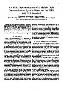
PERFORMANCE MEASUREMENTS
The receiver sensitivity as defined by IEEE 802.15.4 shall be -85 dBm or better [5]. With the proposed demodulator, to get Symbol Error Rate (SER) in order of 10-4, the required Eb/N0 should be 19 dB (Figure 7). The Noise Factor (NF) of RF receiver can be computed using following equation: (
)
(
)
(10)
TABLE 1: COMPARISON OF IEEE 802.15.4 PHY IMPLEMENTATIONS
Parameters
Systemon-chip
SDR on GPP
SDR on ASP (TTA)
Programmability
No
Yes
Yes
Integration with Sensor Nodes
Yes
No
Yes
Real-time Processing
Yes
No
Yes
Low-Cost
Yes
NA
Yes
VIII. CONCLUSION
Figure 7. SER performance
Considering equation (10) [10] with B = 1/Ts, S/N =19 dB and sensitivity = -85 dBm, the noise factor is computed to be 7 dB. Such RF receivers can be fabricated using CMOS process as demonstrated in [11]. The SER performance of the demodulator is in agreement with the IEEE standard. Transmitter CPU cycle requirement is found to be in linear relation with PPDU size as per equation (11). (
)
(11)
The clock frequency to achieve required data throughput of 250 kbps is less than 35 MHz for the TTA processor. The TTA processor for receiver takes around 5930 CPU cycles for processing 1 byte of data. The processing overhead for preamble detection and synchronization is around 32K CPU cycles. The receiver could achieve a data throughput of 250 kbps on a CPU clocked at 200 MHz. The total gate count of the TTA processors (estimated by TTA tool chain) is small enough to be implemented on small silicon area in a low-cost CMOS technology. VII. DISCUSSION A qualitative comparison of System-on-chip implementation (e.g. TI CC2531, Marvell 88MZ100 etc.), GPP based SDR implementation (using GNU Radio, MATLAB etc.) and the TTA implementation of IEEE 802.15.4 physical layer is presented in Table 1. The TTA realization has the software configurability and can be easily integrated with lowcost CMOS process based RF transceiver.
The SDR realization of IEEE 802.15.4 Physical Layer on a TTA processor has been presented. The SER performance of the designed demodulator is in agreement with IEEE 802.15.4 requirements. The designed TTA processor can process the data at required bit rate of 250 kbps. The single core processors are simple enough, have low gate count and can be fabricated on small silicon area. REFERENCES [1]
Corporaal, H.; Microprocessor architectures: from VLIW to TTA,: J. Wiley, 1998. [2] ter e e w r n D transceiver," 17th IEEE International Conference on Electronics, Circuits, and Systems (ICECS), pp.323-326, 12-15 Dec. 2010. [3] Schmid, T.; "GNU Radio 802.15.4 En- and Decoding," September 2006. (TR-UCLA-NESL-200609-06). [4] Dehaese, N.; Bourdel, S.; Barthelemy, H.; Bachelet, Y.; Bas, G.; , "FSK zero-crossing demodulator for 802.15.4 low-cost receivers," 12th IEEE International Conference on Electronics, Circuits and Systems, 2005, pp.1-4, 11-14 Dec. 2005 [5] IEEE Standard 802.15.4-2006, 2006. [6] Proakis, J.G.; Digital Communications, New York: McGraw-Hill, 1989 [7] Jääskeläinen, P.; Guzma, V.; Cilio, A.;Pitkänen, P.; Takala, J.;, " Codesign toolset for application-specific instruction-set processors", Proc. SPIE Multimedia on Mobile Devices, 2007. [8] Kwon, H.M.; Kwang Bok Lee; , "A novel digital FM receiver for mobile and personal communications ," Communications, IEEE Transactions on , vol.44, no.11, pp.1466-1476, Nov 1996. [9] Dehaese, N.; Bourdel, S.; Barthelemy, H.; Bas, G.; , "Simple demodulator for 802.15.4 low-cost receivers," Radio and Wireless Symposium, 2006 IEEE , pp. 315- 318, 17-19 Jan. 2006. [10] Luzzatto, A.; Shirazi, G.; Wireless Transceiver Design,: J. Wiley, 2007, pp. 36. [11] Z lf gh ri A vi B “A w P wer H r n itter/ eceiver C O C” IEEE Journal of Solid-state Circuits, vol. 38, no. 2, Feburary 2003.