2015 International Conference on Industrial Instrumentation and Control (ICIC) College of Engineering Pune, India. May 28-30, 2015
Low cost Hardware-in-Loop for Automotive Application Mr. Abhijeet Taksale1, Mr. Vishwas Vaidya2, Mrs. Priti Shahane3, Mr. Goutham Dronamraju4, Mr. Vivek Deulkar5 Department of Electronic and Tele Communication, Symbiosis Institute of Technology, Pune1, 3 E&E Department, ERC, Tata Motor Ltd., Pune2, 4, 5 1
[email protected] ,
[email protected],
[email protected],
[email protected],
[email protected]. education and robotics [8,9]. In most industries, for developing embedded system, hardware in loop (HiL) testing is used to reduce time-to-market with enhancing quality of product. It involves testing of embedded system in cost effective, repeatable and controlled manner. Use of this methodology, allows developing ECUs even when the end vehicle is not ready and in other cases reduces the iteration time. In automotive industries, it is found that testing of ECUs through HiL is more easier and efficient than testing on real vehicle. Use of HiL, in development and validation of ECUs reduces human risk factor as probabilities of accident are more in real environment "in-vehicle" testing. HiL simulation can be viewed as a combination of virtual prototyping and physical environment. The objective of proposed HiL testing was to simulate an embedded system in virtual environment which is approximated to a real one. Using HiL, we created a virtual environment of vehicle dynamics for testing of an ECU by generating actual world input output signals in real time environment. Figure 1 illustrates, generalized block diagram of HiL testing. In proposed testing, we initially generate signals from HiL in order to emulate controller under test. The outcomes of controller captured by HiL and again subsequent outputs generated by HiL in order to form a closed loop. For HiL testing inputs of controller under test are the outputs of HiL and outputs of controller under test are the inputs to HiL.
Abstract: Hardware-in-loop (HiL) simulation focuses on testing of Electronic Control Units (ECU) in virtual real time environment in order to scrutinize the behavior of controller under test. Use of HiL simulation in development process reduces time and cost involved in verification and validation of the ECU’s development. Generally, HiL systems developed using dSPACE®, National Instruments® and other platforms used in automotive industry are very costly and sophisticated. For less complex systems a low cost HiL testing approach using an existing target hardware can be opted. It may or may not be possible to use existing hardware, as there might be limitations in the availability of pin count, onchip peripherals etc. This paper discusses a case study of Electronic Speed Limiter (ESL) where a low-cost HiL testing technique is being implemented for verification and validation of ESL. The ESL HiL system developed using existing target hardware can simulate different vehicle dynamics, driver behaviors, various road profiles and frictional coefficients in approximation to that of real time environment. The development process of a low cost HIL and research outcomes of ESL testing using the developed ESL HiL are discussed in detail. Developed simulation model increased scope of testing control logic of ESL. The results of HIL testing are found likely to "in-vehicle" testing and at same time controller under test is tested safely with low cost approach. Keywords: Hardware simulation.
in
Loop,
Electronic
Speed
Limiter,
I. INTRODUCTION HIL testing can be applied to a wide variety of systems [1], from simple embedded systems such as room temperature controllers to sophisticated embedded systems like an unmanned vehicle control system. HiL have aided development in several fields, mainly involving aerospace [2,3], automotive [4,5], manufacturing[6], power systems [7],
Figure 1: Block diagram of generalized HiL testing
_______________________________________________________ The authors are with Tata Motors Ltd. and Symbiosis Institute of Technology, Pune India. This work is sponsored by TATA Motors Ltd., Pune India.
978-1-4799-7165-7/15/$31.00 ©2015 IEEE
By emphasizing a mathematical model in HiL, it provides a scope to simulate ECU for prevailing problems. The HiL
1109
III. HIL DEVELOPMENT
environment is mainly composed of an application software model of real system behavior, base software and hardware. In order to develop a HiL specifically for automotive industries, we incorporated an approximated vehicle model. This model provides scope to test ECUs with different test conditions, for example variable frictional coefficient, mass of vehicle and testing with various road profiles.
In automotive industries, most of the ECUs has input pin counts more than output pin counts because output is function of many input signals, which should be compliment in case of HiL board. HiL requires more number of output pin counts than input pin counts. Following table governs the pin mapping of ESL and HiL. Most of ECU used in automotive industries are not enabled with analog output, this problem occurred while developing HiL for ESL controller. The accelerator pedal pressed and vehicle speed are key output voltage signals that to be generated through HiL for testing of ESL.
This paper describes a case study of HiL testing of an onroad electronic speed limiter (ESL). This allowed us speedy development of speed limiter which reduced development time of the controller strategy. This paper includes various test case scenarios and results that use in development stage of ESL controller. This paper is structured in six different sections. Section 2 describes, scope of HiL testing in automotive industries. Section 3 discusses, development of HiL for ESL. Section 4 frames, a case study of ESL controller, discussing the generalized block diagram of proposed HiL testing. Section 5 illustrates, results obtain through HiL testing on ESL controller. Section 6 discusses, the scope of future research in HiL testing. Finally, this paper summarizes the novel low cost HiL testing approach for ESL. II. SCOPE OF HIL IN AUTOMOTIVE INDUSTRIES
Sr. No.
ESL Signals
HiL Signals
1
Accelerator pedal pressed signal
Analog output ( PWM through low pass filter )
2
Vehicle speed
Pulse output
3
Throttle valve opening
Analog Input
Table 1: Pin mapping of ESL and HiL HiL had following development stages.
HiL has a huge impact on automotive test platforms as it not only reduces time but also increases scope of testing. This test platform includes a range of simulations (such as vehicle, ABS, powertrain, etc). Many times, it can be planned to develop a controller even when the end vehicle is unavailable. In such case, HiL testing emulates the controller in virtual environment to further proceed with development process. In “in-vehicle” testing approach, iterations are time consuming. This approach may resolve into a hazardous condition if malfunction of ECU occurs. Many test cases, require simulating ECUs with a range of use-case scenarios related to road conditions, road profiles and vehicle mass. HiL overcomes all this issues and provides an efficient solution on it. It reduces time and cost involve in testing of ECU in “invehicle” approach. HiL can also be expand to test the conditions which not even possible on a vehicle.
x Analysis of ESL : The initial stage of HiL development was to analyze the electronic speed limiter. This indirectly implied the requirements of controller under test only that the inputs will be swapped with the outputs for the HiL. x Hardware selection for ESL HIL : An existing target hardware is selected in such a way that it meets most of the HiL requirements. The selected hardware had partially fulfilled the requirement of on chip peripherals required to generate the analog signal for HiL testing. x Additional hardware requirement : To fulfill the HiL hardware requirement to generate analog signals extra components is added. This hardware modifications is done at circuitry / component level and tested by using some test cases. For example, analog signals is generated from 1V to 4.4 V using PWM and a analog circuit.
HiL developed using dSPACE® [10][11], which is targeted towards TMS320 DSP processors, National Instruments® [12], etc. development tools, by automotive engineers were costly, highly specialized and bulky. While, our proposed HiL is implemented on a low cost hardware based on a target controller that to be tested, which eventually reduced the overall cost involved at different development stages of ESL controller.
x Application and base software development : Now since the hardware was ready the plant was emulated by using mathematical models and hand coding to created virtual environment on the test bench.
1110
x Software/Hardware integration of HiL: At this stage, application and base software is integrated with finalized HiL hardware.
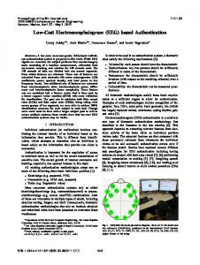
modulated wave with a variable duty cycle which is applied to a RC low pass filter. For example, for 25 % duty pulse width modulated signal, analog circuit produces approx 1.25V. This additional hardware is verified by generating different analog voltage signals for different duty cycles of PWM signal. Analog voltage generated through a first order RC low pass filter had fluctuation in voltage level which was later compensated by replacing first order with a second order RC low pass filter and was tested to have lesser fluctuations. Figure 3 illustrates a analog voltage signal generation with a PWM module and a second order RC low pass filter.
x Verification and validation : This HiL system as a whole is tested with some known test cases to meet the requirements. For example, for any given input there should be a desired output as per the HiL requirements. IV. APPLICATION REFERENCE The controller under test is an electronic speed limiter (ESL) with throttle valve linked with an actuator through mechanical linkage. Figure2 illustrates a block diagram of testing of a ESL controller through HiL. In vehicle, ESL controller takes accelerator pedal and vehicle speed as primary input signals and restrict speed of vehicle as it tries to exceeds beyond certain limit (configurable) by controlling the actuator.
Figure 3: Analog signal signals generation through digital pin using RC low pass filter
To design a second order RC low pass filter, a simulation was developed in Proteus software. The simulation is ran for different values of R and C combinations, to attain optimum values of both.
Figure2: Block diagram of a HiL testing.
A target board was needed in order to fulfill the pin counts required to simulate controller under test in real time environment. Considering pin counts and on-chip peripherals required, a suitable target board is considered as HiL which meets most of the system requirements. The selected HiL hardware has a on-chip pulse width modulation (PWM), real time clock (RTC), analog to digital converter (ADC) and MSCAN module. Initially, there was no such on-chip peripheral on the HiL board, which can generate an analog voltage signal, so a RC low pass circuit is used. V. MODIFICATION IN EXISTING TARGET BOARD In order to generate analog voltage signals, a PWM module was configured to produce 50Hz pulse width
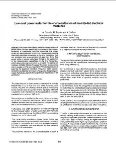
Figure 4: Simulation output of second order RC filter testing
1111
The model is developed in such a way that it can be modified to recreate different driving conditions. This model is integrated in ESL HiL by generating auto code through Matlab Simulink® software. Figure 5 illustrates a simulation model of HiL that was used for electronic speed limiter testing. It generates a vehicle speed depending on percentage of accelerator pedal pressed.
In figure 4, channel A represents the pulse width modulation signal output of a PWM module. Channel B output corresponds to the output from first order RC low pass filter with R=4.7k and C = 47uF and channel C represents output of second order RC low pass filter with both R value as 4.7k and C value as 47uF. VI.
PLANT EQUATION MODELING.
The base software drivers like ADC, PWM which are required for Freescale's® controller of the target hardware are hand written in embedded C. This base software is integrated with the application software using basic architecture (figure6).
To simulate controller under test in virtual environment, a mathematical model which approximates the commercial vehicle dynamics is developed. Equation 1 mention below is used for determining the force produced by the vehicle also called as load equation. ܨൌ ܽ ܾ ʹ ݒ... (1) where, a= Rolling Resistance force=μmg ... (2) ͳ b= Aerodynamic Drag= ʹ ܿߩܣ... (3) v= velocity of the vehicle Coefficient of rolling resistance(μ) = 0.008 Gross vehicle weight(m) = 19500 kg Acceleration due to gravity(g) = 9.8m/s2 Drag coefficient(c) = 0.5 Frontal area(A) = 6.5m2 Air density (ρ) = 1.18
Figure 6: Software architecture of HiL
The developed hardware and software are integrated in order to use in HiL testing. Various signal patterns are generated though HiL before testing ESL controller.
For a commercial vehicle of 19500 Kg GVW, it took 24 sec to accelerate from 0 to 48 km\hr. Hence 0 to 20 km\hr in nearly 9.6 sec (approx). Therefore,
HiL testing is perused in the following steps.
F =19500 x {[( 20-0 )/ 3.6]}/10 = 19500 * 0.556 = 10000 N approx.
x HiL provides accelerator pedal signals as analog signals to the ESL controller.
From the performed experiments on test vehicle and after calculations, final outcome after some assumption was for 100% throttle valve opening, vehicle produces 10,000N force.
x After receiving accelerator pressed signals ESL controller operate opening and closing of a throttle valve through actuator. x HiL senses opening percentage of throttle valve with a throttle valve sensor using on-chip analog-to-digital converter. This throttle valve percentage opening was then fed to application software. x The application software gives vehicle speed as an output depending on vehicle dynamics.
Figure 5: Simulation diagram of HiL
1112
x As soon as, the vehicle speed exceeds the certain limit decided by ESL controller, it operates actuator to maintain constant speed even if the accelerator is fully pressed. VII. RESULTS Figure 7 illustrates, the simulation input corresponding to accelerator pedal pressed. HiL uses this proposed model to generate vehicle speed signals depending on throttle valve percentage opening. For different throttle valve percentage opening, model responds with different slope of vehicle speed.
Figure 7: Simulation inputs and output results
Figure 7 also represents actual output of software simulation corresponding to vehicle speed in the presence of ESL. The vehicle speed values are in kmph and accelerator pressed signals are in percentage. The controller under test is programme to limit the speed of vehicle to certain limit. The HiL testing is successfully carried out to smoothen the response of actuator by achieving min jerks, produced while maintaining constant vehicle speed. VIII.
FUTURE WORK
As per discussion, future work will include designing of a real time model which will additionally generate engine RPM as output, depending upon throttle valve opening percentage, gear position, vehicle speed, etc. Proposed modification allied to engine RPM will increase number of test cases. Form this, again a higher level C auto code will be generated by Matlab® software. This updated HiL will be tested with vector CANoe tool on a virtual CAN bus environment, to develop a wellorganized communication subroutine. A NI's Labview® based GUI will be develop to observe the present stage of accelerator pedal, vehicle speed, engine rpm, etc. In final validation stage of ESL, controller will be tested with driving cycle representing a traffic condition[13]. ACKNOWLEDGEMENT The authors are indebted to many people who have aided in this work by sharing their technical guidance for proposed HiL testing. The authors would like to acknowledge the efforts of Mr. Rahul Mahindrakar, Mr. Gaurav Korad, Mr. Anand Kalode, Mr. Vandan Sharma and Mr. Amar Penta. This research was sponsor by Tata Motors Ltd. India and supported by Symbiosis Institute of Technology, Pune.
1113
CONCLUSION
[5] Isermann R, et. al.," Hardware-in-the-loop simulation for the design and testing of engine-control systems", Control Engineering Practice, 1999. [6] Stoeppler G,et.al.," Hardware-in-the-loop simulation of machine tools and manufacturing systems", Computer control engineering , 2005. [7] Liu Y, et.al.," A novel approach to power quality assessment: real time hardware-in-the-loop test bed" IEEE Transaction Power Delivery, 2005 [8] Wojciech G.et.al "Hardware-in-the-loop simulation and its application in control education", 29th ASEE/IEEE Frontiers in Education Conference,1999. [9] Carufel J, et. al. ,"Control strategies for hardware-in-loop simulation of flexible space robots", proceedings of IEEE control theory application, 2000. [10] Grega, et.al."Hardware-in-the-loop simulation and its application in Control Education”, Frontiers in Education Conference, vol2,1999.10.1109/FIE.1999.841594 [11] Deepa Ramaswamy. et. al. ,"A case study in hardware-in-the-loop testing: development of an ECU for a hybrid electric vehicle", proceedings of SAE, 2004-01-0303. [12] Maxwell, et.al," Hardware-in-the-loop testing of GM two-mode hybrid electric vehicle", Proceedings of IEEE, 2010, 10.1109/ COMPEL. 2010. 5562427. [13] Sanghpriya H et.al., "Development of real-world driving cycle: Case study of Pune, India".
This paper proposes a novel low cost approach in HiL testing devoted to an on-road electronic speed limiter of a commercial vehicle. Indeed, this methodology includes a vehicle model simulation to test control logic of ESL system followed and testing of ESL system with a actuator based electronic throttle control as controller under test. The developed HiL articulate an industrial real time emulator that simulate according to input signals and provide results alike that of a real vehicle plant. Testing results, helps in scrutinizing performance of actuator using various driving cycles and added value at various phases of development process of controller under test. HiL tests are performed in a reproducible, controllable and efficient way to create a real time environment alike an outdoor test scenarios.
ABBREVIATIONS HiL ESL ECU PWM RTC ADC CAN
REFERENCES: [1]Sheran Alleset. al., "Real time hardware in the loop vehicle simulation", Proceedings of IEEE, 1992. [2] Duke E., "V&V of flight and mission-critical software", proceedings of software IEEE, 1989, pp 39–45. [3] Johnson E, et.al., "Use of flight simulation to complement flight testing of low-cost UAV’s", Proceedings of AIAA conference of model simulation technology, 2001. [4] Hanselmann H. "Hardware-in-the-loop simulation as a standard approach for the development, customization, and production test of ECU’s", proceedings of SAE, Paper Number 930207, 1993.
1114
Hardware in Loop Electronic Speed Limiter Electronic Control Unit Pulse width Modulation Real Time Clock Analog to digital Convertor Controller area network