such application is a consumer video phone (1) over analog phone lines using the ... IEEE 1994 CUSTOM INTEGRATED CIRCUITS CONFERENCE;. 115.
A Low Cost Application Specific Video Codec for Consumer Video Phone S. Khalid Azim’ , Musa Jahanghir2, Reza Aghevli,Carl Holmqvist, Jose Mena, Mourad Takla, Mohan Yellayi, Bruce Edwards3, Vijay Maheshwari4, Neil Weste3 AT&T Bell Laboratories, Allentown, Pennsylvania ’now with Crystal Semiconductor, Austin, Texas 2Compression Labs. Inc., San Jose, California VLW, Burlington, Massachusetts now with C-Cube Microsystems, Milpitas, California 1. Introduction:
Variations of DCT based algorithms are currently widely used for various video compression applications. One such application is a consumer video phone (1) over analog phone lines using the PV2TMvideo compression algorithm from Compression Labs, Inc. Mass acceptance of the video phone requires highly integrated and IOWcost solution. Many of the general purpose IC solutions for compression currently in the market do not meet these requirements. As a result, we developed an application specific video codec IC, called SAM. It works with AT&T’s DSPl616 processor for performing all the digital video processing functions required by the video phone. Our implementation demonstrates that this approach provides a very cost-effective solution. SAM integrates a wide range of functions including video preprocessing on incoming pixels from the camera, motion estimation and compensation, reconstruction of video frames from compressed data, video post-processing, inserting picture-in-picture, graphics overlay, DRAM controller, and an host interface. The chip, fabricated using AT&T’s 0.9 pm double-level metal CMOS process, has been successfully tested in a proto-type system.
blue chroma, Cb=B-Y; where R is red and B is blue color. w 224 active lines/frame; w 128 luma samples/line; 32 C, and 32 Cb samples/line; 8 bits/sample. The above format gives a raw data rate of >10 Mbits/s. Since the video data over the analog phone lines must be limited to < 10 kbits/s, input data rate must be reduced by over a 1OOOX while maintaining acceptable picture quality. The first step in accomplishing this is pre-processing.
B. Re- and post-processing: Pre-processingfunctions include vertical reduction, temporal filtering, and spatial filtering. Vertical reduction is achieved by averaging every two luma lines and averaging every eight chroma lines resulting in 112 linedframe of luma and 28 linedframe each of the two chroma components. Temporal filtering is performed next on both luma and chroma samples in order to reduce noise and smooth out motion. It is described by the following equation. X’, = X, + b(X’,I - X), if I(X’,-, - X,)I e Threshold - X), then b = f(X,’ else b = unsigned constant
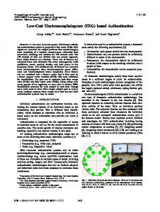
In this paper we first present the algorithm and system requirements followed by a description of the ASIC’s architecture. Finally, results are summarized in Sec. 4. 2. Algorithm and System Requirements A. Overview: PV2TMis a DCT based video compression algorithm. The block diagram in Fig 1 shows the major functions including pre- and post-processing of video data.
(EQ 1)
where X is incoming pixel, X’ is filtered pixel, n is current frame, and n-l is previous frame. Finally, higher spatial frequencies are filtered out by applying a 3x3 filter kernel to each luma frame.
The video signal coming from a NTSC source is initially filtered and digitized by an analog IC, SARA, which provides SAM with video data in the following format.
In post-processing, the major functions are assembling frames for display, interpolation, and color conversion to R-G-B format.
= 30 framedsec - Each composite frame consists of three components: luma, Y;, red chroma, C,=R-Y; and
C. Block Processing: Inter-frame and intra-frame redundancies in the video frames are eliminated
6J.l IEEE 1994 CUSTOM INTEGRATED CIRCUITS CONFERENCE;
115 0-7803-1886-2/94 $3.00 01994 IEEE
DCT
1-1
t transmit ref. frame memory
reconstructed block
normal-
U
Implemented In ASIC
0
Implemented as DSP code Frame memory
FIGURE 1. DCT based motion-compensated Inter-frame and intra-frame video coding scheme. Hardwarelsoftware partitioning between ASIC and DSP code is also shown. through motion estimation and DCT. For motion estimation each frame is divided into 56 16x16 blocks of YL data and four 16x16 blocks of each of C, and Cb data. For each 16x16 pixel block of the current frame, the motion estimation engine searches the previous transmit reference frame to find the best matched (or prediction) block. This is based on finding the block with minimum total absolute error (TAE). TA E = Xj=o-15Xi=o-15lf( i,j) -f '(i,j) I
(EQ 2)
where f(i,j) are current block's pixel values and f'(i,j) are pixel values of reference frame's search block. The search extends over a region +/- 5.75 pixels in X and Y directions around the current block's location. This results in motion vectors and an error block containing the pixel differences between the current block and the predicted block. This error block is then discrete cosine transformed into the frequency domain using 8x8 subblocks. The procedure just described is known as DPCM mode. In any case, the DCT output is normalized and quantized, and the non-zero DCT coefficients are encoded and stored in a rate buffer for transmission. The quantized coefficientsalso go through an inverse normalization and inverse DCT operation, the result of which is added to the predicted block from the previous reference frame. This results in a reconstructed block which is stored in a new transmit reference frame being assembled block-by-block.
On the receive side, a copy of the reference frame is also maintained. This is used to reconstruct the current frame by using the received motion vectors and the encoded pixel error data. E. System Functions: In addition to the algorithmic operations described above a high level of system integration is achieved by including following system functions in SAM. (a) Insert picture-in-picture for displaying in any of the four quadrants. (b) Overlay bitmapped graphics on the display. (c) Display mirrored or un-mirrored image. (d) Store and retrieve individual image frames. (e) A DRAM memory controller for arbitrating accesses by various functional units and interfacing with the memory. (9 A DSP1616 host interface. 3. Architecture
A. System Architecture: A simplified block diagram of the video subsystem is shown in Fig 2. An analysis (2) of the various tasks showed that unlike most existing video codec solutions, the DCT and IDCT functions are best performed in software in the DSP1616. The DSP also performs quantization, zig-zag and run length coding (RIA), and variable length coding (VLC), as well as task scheduling and servicing system requests. This makes the most of DSP1616's resources and capabilities. Most of the algorithm specific, compute intensive tasks are allocated to SAM which is designed to implement them efficiently. A
6.7.2 116
block diagram of SAM is shown in Fig 3. Pre-processor, block processor, and post-processor are described here. 6. Pre-processor:The preprocessing functions are implemented as pipe-lined, hard-wired logic in which all the operations required on the 128 luma pixels and 64 chroma pixels per video line are completed in one line period of 63 ps. This includes vertical reduction, temporal filtering, and spatial filtering. The circuit shown in
256x16 DRAM framememory
-
System controller
___
cr+* cb+
SARA: AID, DIA, --+ SAM: analog +Video Cudec processin$ I
A typical sequence of DPCM mode block processing operations by SAM are as follows (refer to Fig. [5]).A
YL-)
u , E
I
block statistics. A block diagram of the block processor is shown in Fig. [5].The DSP initiates block processing sequences in the SAM by writing 12 bit command words an instruction queue in the SAM. This queue is two instructions deep.
I
I
A
II
DSP1616
+
Look UP -W table
+
I
from temporal frame memory
I
FIGURE 2. Simplified block diagram of video subsystem
I
n
Fig 4 implements the temporal filter described by Eq. [l]. Filtering is done on one luma or chroma sample at a time.
to temporal frame m'em. and spatial filter FIGURE 4. Temporal filter
The pre-processed frame is written into one of two spatial frame buffers in the DRAM. The other spatial frame buffer is read by the block processor for motion search.
C. Block Processor: Block processing tasks performed by SAM includes motion search, generation of motion vectors, and computation of error block and several , Video in
Video out
processo
process0
3DRAM memory controller
16x16 block of data from frame memory is loaded into CB and its dispersion value computed by MSAU. A 28x28 search window is next loaded with odd lines in SWO and even lines in SWB. Motion search is executed in four passes: at 2 pixel, 1 pixel, 1/2 pixel, and 1/4 pixel resolutions. The MSPEA with its five processing elements computes Eq. [2] for this purpose. It uses sub-pixel values generated by SUBPIX. After the best prediction block is found the error block is computed by DPCMAU and transferred to DSP. A copy of the prediction block is also stored in ZZX or ZZY. The DSP, after completing its part of the block processing operations sends the encoded data out for transmission and also writes back the inverse normalized error block into CB. Using DPCMAU, this is added back to the prediction block stored in ZZX or ZZY. The resulting reconstructed block is stored in frame memory after optional output noise reduction by ONR.
(motion search)
D. Post-processor:The post processing circuit reads out the desired frames from the DRAM and assemI bles a display frame based on a graphics bit-map also stored in the DRAM. Insertion of PIP and graphics DRAM DSP1616 overlay are controlled by the bit-map. Next, luma lines are doubled, and chroma lines are interpolated horiFIGURE 3. Block diagram of SAM (ASIC)
+
!
6.7.3 117
CB: 16x16 current block buffer SWE,SWO: 14x28 odd and even line search window buffer ZZX,ZZY 16x16 temporary buffer MSCU: motion search engine control unit A , I I MSAU: motion search arithmetic unit DPCMAU: DPCM arithmetic unit DPCMAU MSPEA SUBPIX: enerates subMSCU pixel va ues. MSPEA: motion search processing element array ONR: output noise reduction FIGURE 5. Block processor: functions include motion estimationlcompensation
I
?
zontally and vertically. This results in 128 samples x 224 lines each of YL, C,,and Cb components per frame. Next, the luma and chroma components are color converted to generate R,G,B components. Finally, the samples are interpolated and up-sampled to a 256 x 224 pixel frame. This is sent to the display after conversion to analog signals by the SARA chip.
I
I
1
References: (1) S. Early, A. Kuzma, and E. Dorsey, “The VideoPhone 2500 - video telephony on the public switched telephone network,” Al&T Technical Journal, vol. 72, pp. 22-32, Jan/Feb 1993. (2) David Blaker and Hugh McLaughlin, AT&T-ME/CLI internal communications.
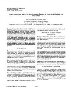
4. Implementation and Results: SAM was designed and fabricated using AT&T’s 0.9 pm double-level metal CMOS process and assembled in a 132-pin plastic quad flat package. A combination of standard cells and macro-blocks were used for layout. Several sections of the chip were designed usin AT&T’s logic synthesis tool. The chip size is 114 mm with 0.5 million transistors. It passed all test vectors on Advantest IC tester and has been successfully integrated in a proto-type system. Test results show that with a 30 MHz clock, SAM processes over 25 frames per second. Exact frame rate depends on the frame characteristics and capacity of transmission media.
4
We have demonstrated that an off-the-shelf DSP with an ASIC co-processor provides a cost-effective solution for many video compression applications. Acknowledgments Thanks are due to Eric Dorsey, Hugh McLaughlin, Ken Swinehart, and David Wang of Compression Labs, and David Blaker and Andy Kuzma of AT&T for their help with SAM specifications.
FIGURE 6. Microphotograph of the SAM chip
6.7.4 116