IEEE TRANSACTIONS ON INSTRUMENTATION AND MEASUREMENT, VOL. 55, NO. 2, APRIL 2006
521
Low-Cost Visual Sensor Node for BlueTooth-Based Measurement Networks Luigi Ferrigno, Associate Member, IEEE, Antonio Pietrosanto, and Vincenzo Paciello
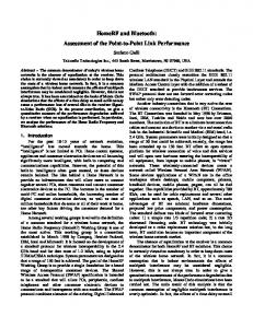
Abstract—This paper proposes a wireless visual sensor comprising of a low-cost grayscale camera as the sensing hardware and a BlueTooth (BT) 100-m slave module as the transmission hardware. The latter enables the sensor to be inserted as a node in a medium-range BT measurement network. The proposed sensor, which is designed to satisfy precise specifications in terms of image-transfer rate and power consumption, represents a good image-acquisition solution in a wide range of applications where hardwiring between camera and image processor is undesired. This paper describes the hardware used and the overall operating principle behind the sensor, discusses the sensor-node performance, and reports the results of reliability tests. Index Terms—BlueTooth (BT), low power consumption, plugand-play devices, real-time measurement, sensor networks, smart sensor environments, visual sensors, wireless sensors. Fig. 1. Example of wireless sensor network.
I. I NTRODUCTION
A
DVANCES in microelectronic hardware technologies, and the growing need to measure quantities spread over a wide geographical area, have permitted the diffusion of lowcost low-power multifunctional sensor devices. Usually, these devices do not work in isolation but are used to make up hundreds of ad hoc sensor nodes spread around the measurement environments. These sensor nodes communicate with each other to establish a sensing network. This network can provide access to information anytime and anywhere, by collecting, processing, analyzing, and disseminating data, and creating a hierarchical smart environment. Two of the great advantages of these sensor networks are that they do not require particular infrastructures or human control. They sense, compute, and actuate in the physical environments, thus enabling them to be used in several applications [1]–[4]. Today, important steps in communication technology have made setting up wireless networks possible. The advantages of wireless connection in sensor networks are easy to understand. 1) They give higher flexibility in sensor placement and allow measurements to be made everywhere both in open and closed spaces. 2) They allow making measurements of moving objects. 3) They can minimize human intervention and management. 4) They can work in hostile and unattended environments [5]. Manuscript received June 15, 2004; revised December 14, 2005. L. Ferrigno is with the Dipartimento di Automazione, Elettromagnetismo, Ingegneria dell’informazione e Matematica Industriale (DAEIMI), University of Cassino, Cassino (FR) 03043, Italy (e-mail:
[email protected]). A. Pietrosanto and V. Paciello are with Dipartimento di Ingegneria dell’informazione e Ingegneria Elettrica (DIIIE), University of Salerno, Fisciano (SA) 84084, Italy (e-mail:
[email protected];
[email protected]). Digital Object Identifier 10.1109/TIM.2006.870126
Their wireless architecture makes it possible to remotely access sensor data by providing sink nodes that connect them to other networks using wide-area wireless links (see Fig. 1). On the other hand, a limitation of a wireless sensor is its autonomy (i.e., the mean time between battery replacements). Energy is typically more limited in sensor networks than in other wireless networks because of the nature of sensing devices and the difficulty in recharging their batteries. Therefore, power consumption is an important parameter for the development and the construction of these sensors. There are many wireless technologies on the market. Some of them are characterized by a high-range coverage area, high costs, and high power consumption such as global system for mobile communications (GSM), general packet radio service (GPRS), and digital enhanced cordless telecommunication (DECT). Others are characterized by lower coverage area, low costs, and lower power consumption such as BlueTooth (BT), IEEE 802.11, and Wireless Fidelity (WiFi). From an economical point of view, the latter category is promising for use in sensor-network architectures. In particular, among the low-cost wireless technologies, one of the most used in industrial and commercial environments is BT. BT is a radio link initially designed to replace cable connections among portable and/or fixed electronic devices. In its first realization, BT was developed for a plug-and-play wireless network over a short-range area (10 m), but after some evolution, medium-range BT connections (up to 1 km) are now present on the market. Its key features are robustness, low complexity, low power, and low cost. BT operates in the unlicensed ISM band at 2.4 GHz, with a symbol rate of 1 MS/s. BT modules can provide a point-to-point connection (only two BT modules involved), or a point-to-multipoint connection. In the point-to-multipoint connection, several BT units share the physical channel, and
0018-9456/$20.00 © 2006 IEEE Authorized licensed use limited to: National Taiwan Ocean University. Downloaded on May 04,2010 at 01:59:25 UTC from IEEE Xplore. Restrictions apply.
522
IEEE TRANSACTIONS ON INSTRUMENTATION AND MEASUREMENT, VOL. 55, NO. 2, APRIL 2006
bandwidth to support image transfer, the sensor node can be easily inserted in a BT piconet network. This sensor may be an optimum solution for wireless applications that prefer low costs and low power consumption to high area coverage. The key features of the sensor are its very low cost (the final cost will be as low as commercial digital cameras), long battery life, and small size. In the following, both the hardware and the adopted software solution will be described. The sensor is characterized in terms of distance, throughput, and reliability, and a possible application for it is described. II. P ROPOSED S ENSOR N ODE A. Hardware A sensor node usually consists of five components: 1) sensing element; 2) processor; 3) memory; 4) transceiver; and 5) power supply. As reported in Fig. 3, the proposed architecture can be divided into five main blocks, each one having been developed taking into account the requirement for low power consumption. The following gives a description of each component. Fig. 2. (a) Example of a BT piconet. (b) Possible BT wireless sensor scatternet.
two or more units sharing the same channel form a piconet [see Fig. 2(a)]. A piconet allows one BT master module only, while the other modules act as slaves. Up to seven slaves can be active simultaneously, while a maximum of 255 slaves can be present in the piconet using the hold, sniff, and park modes. Piconets may share the same area, thus creating a scatternet. The built-in BT piconet and scatternet characteristics can meet the need for connecting sensors in a smart wireless network [see Fig. 2(b)] [6]–[8]. In the main class of sensor networks, there are significant cases that require the use of image-based (i.e., visual) sensors. This is a topical and attractive task both for research and industrial applications. An image-based sensor could be successfully used in many areas where particular production or high-quality requirements create the appropriate conditions for introducing visual measurements [9], [10]. A wireless imagebased sensor is useful for handling various tasks, such as environmental measurements, shape recognition, positioning of parts after gripping (the sensor could be placed in a mobile robot), and visual-quality tests after assembly. In addition, a wireless image-based sensor may be used to make remote measurement with old analog measurement instruments, or to acquire the output of sensors with visible analog interfaces. Obviously, a wireless image-based sensor, besides having the aforementioned cost and autonomy characteristics, should assure the necessary bandwidth to support the required video transfer and streaming. Based on their experience of wireless connection [11]–[13], instrument interfacing [14], and image-based measurements [12], the authors present, in this paper, a low-cost visual sensor with a BT interface. Having been developed to reduce power consumption to a minimum and to have the necessary
1) The sensing element is a 384 × 288 pixels grayscale digital camera. This camera uses an 8-bit digital resolution over a charge-coupled device (CCD) matrix of 4.2 × 3.2 mm, thus allowing a dimensional pixel resolution of 11 × 11 µm and an intensity resolution of 256 gray levels. The digital video port supplies continuous-byte wideimage data. The adopted camera has many interesting features, some of which are controlled using 4-bit register-based commands. The on-chip programmable features include variable frame rate, exposure setting, gain control, and gamma correction. These functions may be useful to allow good acquisitions in different operating conditions. The adopted camera needs a 5-V power supply providing less than 20 mA in the active state (@50 ft/s) and less than 100 µA in the standby mode. 2) The central part of the proposed sensor node is the microcontroller module. Its main functions are control of the sensing element, synchronization of the data transfer between sensor and memory, and control of the saved data transmission on the wireless channel. The processor module uses a Microchip PIC16LF877 low-power microcontroller. A useful feature of this microcontroller is that it can operate in a low-power-consumption mode (in sleep mode). During this phase, the normal I/O processor activities are stopped and the maximum current required from the device is less then 0.1 µA. The microcontroller can be woken up from the sleep mode by an external reset, using a watchdog timer wake up or changing the value of a number of specific I/O pins. If the interrupt occurs during or after the execution of a sleep instruction, the device will immediately wake up from sleep. The sleep instruction will be completely executed before wake up. These features are important for saving the overall power. 3) The memory module is a 256-kB first-in first-out (FIFO) flash RAM device. The FIFO architecture is chosen to
Authorized licensed use limited to: National Taiwan Ocean University. Downloaded on May 04,2010 at 01:59:25 UTC from IEEE Xplore. Restrictions apply.
FERRIGNO et al.: LOW-COST VISUAL SENSOR NODE FOR BLUETOOTH-BASED MEASUREMENT NETWORKS
Fig. 3.
523
(a) Block diagram and (b) image of the BT wireless sensor setup.
minimize both the digital I/O pins used in communicating with the microcontroller and the addressing time. The main characteristics of the selected RAM are high-speed asynchronous serial access and read/write cycle time of about 25/40 ns. The memory provides eight digital input and eight digital output lines. The former are connected to the sensing hardware, while the latter are connected to the processor module. Also, the selected memory assures the required feature of low power consumption, requiring about 200 mA during the writing/reading operations and practically zero in the standby mode. 4) The transceiver module comprises two main parts: a) a BT master/slave transmission module and b) a radio frequency (RF) module. a) The BT transmission module is a 1.1 compliant master/slave module. This is a class-1 power (100 m) module equipped with transistor transistor logic (TTL) RS232, universal serial bus (USB), and pulse-code modulation (PCM) interfaces for different communication necessities. The TTL RS232 communication channel was used for communicating with the processor module. The selected module allows a 3.3-V power supply and has a power consumption of about 400 mW during the connection phase. b) The RF module is a very-low-cost micro amps RF receiver. The module range is up to 1 km and the current consumption during the receiving time is about 70 mA at 3.3 V and practically zero during the other time. The data output of the RF module is connected with a suitable decoder module that can compare the incoming sequence with a 12-bit code. The reason for both RF modules being present will be described in the next section. 5) The battery package comprises of two high-capacitance battery sets. The former, via two high-efficiency stepdown circuits, supplies the processor and transceiver modules, while the latter supplies the sensing hardware and the memory modules.
The total price of the components used to assemble the sensor prototype is about 100 Euros. In an industrial production run of a few thousand items, the price of a sensor node could be well below the actual one. B. Acquiring and Transmission Process and Power-Management Procedure As described in the introduction, the goal of this study is to assemble a low-cost BT-based visual sensor characterized by a considerable lifetime (i.e., the mean time between two battery replacements). To obtain the required lifetime, lowpower devices together with suitable architectural and software are needed. The general idea is that the overall sensor-node architecture is always maintained in a low-power state and that the other sensor parts are powered up only for the necessary time. The only device that is always powered up is the microcontroller and it allows two operating states: active and sleep. The former is used during the acquisition, storing, and transmission procedures, whereas the latter is activated if none of these operations is required. The sleep-mode state can be woken up using several specific I/O pins. In the proposed sensor, one of these pins is connected to the decoder device output. To enable the microcontroller to power the other devices that make up the sensor, these are connected to the power batteries through voltage regulators enabled by a number of microcontroller I/O pins. The wireless RF part of the sensor device will never be turned OFF, since this is the only mode to receive commands or events from the user. The presence of both the RF and the BT wireless modules require particular considerations. If two wireless modules appear to be a useless redundancy, the RF module is indispensable since the BT module has a considerable power consumption (about 30 mA) even in the standby mode. This does not match the need for overall power consumption to allow long-term duration of the sensor-node battery package. Hence,
Authorized licensed use limited to: National Taiwan Ocean University. Downloaded on May 04,2010 at 01:59:25 UTC from IEEE Xplore. Restrictions apply.
524
IEEE TRANSACTIONS ON INSTRUMENTATION AND MEASUREMENT, VOL. 55, NO. 2, APRIL 2006
The microcontroller also sets all the required parameters on the CCD camera, lets the image acquisition start, and allows the acquired pixels to be transferred to the FIFO memory. 5) When all the image pixels are written on the FIFO memory, the microcontroller creates suitable BT packets and transmits the overall information to the master module. 6) At the end of the acquiring and transmission processes, the microcontroller waits for a suitable time to see if new acquisitions are needed. If this is not required, all the previously powered-ON devices are turned OFF and the microcontroller places itself in the sleep mode. C. Flow Control Management and Improved Reliability
Fig. 4. Block diagram of the power consumption for each state of the acquisition procedure.
the RF module is entrusted with the sole task of receiving, decoding, and transmitting the turn-ON command sent by the user to the BT module. The idea can be described as follows: 1) During the microcontroller sleep-mode state, the RF module is in a standby state (about 30 mA) while the BT module is powered OFF. 2) If a decoded sequence arrives, the BT module is powered ON and becomes ready to receive commands and events. At the end of the measurement procedure, the sensor returns to state 1). This procedure makes it possible to save power. The wake-up procedure may also be implemented via software routines. However, this approach could require the microcontroller to have been kept in an active state, and hence consume more power. Fig. 4 shows a block diagram of possible states in the proposed acquiring procedure together with their relative power consumption. The acquiring procedure can be described as follows. 1) The arrival of a data stream on the RF module starts the activation of the decoder module. If the stream matches the decoding sequence, the activation of a microcontroller interrupt is obtained. 2) A wake-up service routine subsequently turns the microcontroller ON and starts the acquisition process. The first operation carried out by the microcontroller is to turn ON the BT module. 3) The microcontroller carries out all necessary operations to establish communications with the BT module. In particular, the microcontroller lets the BT module enter a discoverable status, and successively, a master-to-slave connection is obtained between the sensor and a remote data-acquisition station. 4) Successively, if the user needs an acquisition, the microcontroller powers ON the CCD camera and the FIFO memory, and carries out all the required reset and selftest operations for each device set in a ready status.
Two parameters are important for evaluating the performance of a wireless sensor: 1) throughput and 2) reliability. The former parameter determines the amount of information that the sensor is able to acquire and dispatch in the time unit; the latter is indicated by the failure percentage. Several architectural choices have been made to improve these. The sensor node was developed to acquire single-shot images and to allow the storing of an image stream of about ten images with a maximum frame rate of 1 ft/s. The proposed CCD camera uses 384 × 288 pixels for each acquired grayscale image, with a consequent byte rate of 108 kB/s. This is a considerable high rate compared to the microcontroller clock rate and the BT transmission rate and makes it almost impossible to perform the acquisition and the transmission of the images with the right time and motion. The camera module is therefore directly connected to a high-performance FIFO memory, entrusting the controller role to the microcontroller only during transmission. The only task the microcontroller has to carry out during image storing is to halt the memory during camera start-up time, avoiding the storage of bad bytes. The controlling handshake is implemented using an ad hoc wired or three-line bus that connects up the microcontroller, the memory, and the sensing hardware. The FIFO memory proposed in this paper has a storing capability of 256 kB only, but in its final version, a 5-MB electrically erasable programmable ROM (EEPROM) memory will be used. As far as reliability is concerned, the sensor node can be divided into three functional parts: 1) the camera and the memory; 2) the microcontroller; and 3) the wireless transmission and receiving system. These are the most complex parts in the realized system, and it is more probable to find errors both at the development stage and in operating conditions. Several diagnostic tests carried out on these three parts highlighted the weakest point of the sensor, namely, the reliability of the BT transmission system. A BT transmission failure may occur due to several causes. Among these, the most probable are buffering errors in the transmitting module, or the presence of noise, fading, interference, and obstacles on the wireless channel. Several software routines have been developed, both in the host device and in the sensor node, in order to improve the capability of transmitting uncorrupted data even when there are environmental noise or obstacles.
Authorized licensed use limited to: National Taiwan Ocean University. Downloaded on May 04,2010 at 01:59:25 UTC from IEEE Xplore. Restrictions apply.
FERRIGNO et al.: LOW-COST VISUAL SENSOR NODE FOR BLUETOOTH-BASED MEASUREMENT NETWORKS
When a BT packet is transmitted from the master to the slave BT device, the latter returns an acknowledgment packet to declare the transmission having taken place correctly. In the absence of a response or in the case of a negative acknowledgment, the slave can retransmit the packet, if implemented. The retransmission number can be decided during the master/slave connection procedure. Therefore, the transmissiontime length is not predictable but depends on the number of retransmissions required. If the slave module receives new packets to be transmitted, while it has not terminated its previous transmission due to wireless channel noise, a bufferfull error may occur. To prevent this possibility, a flow-control routine has been implemented on the microcontroller. The main steps in the implemented routine are 1) At the beginning of the transmission process, the whole BT slave-module transmitting memory is filled. 2) Only after a packet has been received from the master, and the consequent transmission complete event has occurred, is the transmission memory refilled with the required bytes. If the packet under consideration has not yet been transmitted, after the expected retransmission number, it is rejected and the sensor tries to send the successive packet. To allow the master to know if a packet has still to arrive or not, each of these are numbered using a hexadecimal number written in the protocol/service multiplexer (PSM) field of the logical link control and adaption protocol (L2CAP) packet. A software routine has been implemented on the sensor-network host module, which is capable of replacing missing pixels with the values obtained using the closest well-received pixels. This allows good image reconstruction and recovery even when a significant number of pixels have been missed. Both the bufferfull and the channel-noise errors can be compensated for using these routines.
525
Fig. 5. Measurement station for the throughput evaluation. TABLE I RESULTS OF THE RELIABILITY TEST
III. M ETROLOGICAL C HARACTERIZATION OF THE S ENSOR AND A P RELIMINARY A PPLICATION E XAMPLE After setting up the sensor node, a first metrological characterization was carried out to evaluate the reliability of both the sensor and the network architecture. As far as reliability is concerned, the characterization was focused on detecting and repairing the critical aspects of sensor operating conditions; first, a throughput analysis determined both the time the network needs to acquire and dispatch the sensed image and the time weight of each element in the total time as a function of the transmitting distance. To evaluate the reliability of the network, a suitable measurement station was built (Fig. 5). This was comprised of a sensor node and a PC equipped with both a BT master module and suitable software capable of sending BT host controller interface (HCI) stack commands to the sensor. The performance of the network was tested by analyzing the number of failures in the execution of some crucial transmission operations such as inquiry, connection between master and slave, and the transmission of a particular data packet of the same length as the acquired image. Several tests were carried out in open and closed spaces. Table I lists some of the results obtained, respectively, at 2 m in a closed space without obstacles, 10 m in a closed space in the presence of obstacles such as a wall,
and 50 and 100 m in an open space. Each test was carried out considering 50 consecutive experiments. The first column in Table I indicates the executed commands, whereas the last one lists the failure events.
Authorized licensed use limited to: National Taiwan Ocean University. Downloaded on May 04,2010 at 01:59:25 UTC from IEEE Xplore. Restrictions apply.
526
IEEE TRANSACTIONS ON INSTRUMENTATION AND MEASUREMENT, VOL. 55, NO. 2, APRIL 2006
TABLE II ESTIMATED SENSOR-NODE PERFORMANCE
Fig. 6. Possible sensor application: (a) the measurement setup; (b) the acquired image.
of retransmissions, related to the implemented flow control. TTLCMEM is independent of distance and is the same for all the tests carried out. Fig. 6 shows a possible application of the sensor to acquire and transmit the output of an old analog voltmeter. IV. C ONCLUSION The paper presents a visual sensor node equipped to be inserted in BT wireless networks. The sensor design is driven by three main specifications: low cost, energy saving, and enough bandwidth for image transfers. The solutions adopted enable the sensor node to be put on the market at a price comparable with that of a low-cost commercial digital camera. Each image acquisition requires a power consumption of about 3.5 mW · h and a transmission time not more than 35 s.
The results of Table I show that the most critical operations in the network connection are the inquiry and connection procedures, since some environmental conditions, such as electromagnetic compatibility (EMC) disturbances or RF obstacles, may deteriorate radio signal quality. Once the connection has been made, the implemented flow control makes it more difficult for a transmission break to occur. The aim of the throughput analysis is to highlight the performance of both the entire network and each constituent element of the sensor. In order to do this, a suitable measurement station was set up comprising of a Tektronics TDS540d four-channel scope, a host station, and one sensor. The host station was comprised of a PC equipped with a BT master module. The throughput tests were carried out in the same operating conditions as the reliability test and three times (namely, TTOTAL, TACQ, and TTLCMEM) were estimated. TTOTAL is the total time the system requires to perform the sensor identification, the master–slave connection, and an image acquisition; TACQ is the time required to perform only the overall image transmission; and TTLCMEM is the time required to transfer the acquired image from the camera to the FIFO memory module. For the 50- and 100-m tests, the overall times, TTOTAL and TACQ, were evaluated using a PC software routine, since it was not possible to connect both the slave and master PC modules to the digital scope. Fifty experimental tests were carried out, and the results obtained are listed in Table II. It is evident how TTOTAL and TACQ depend on the distance between master and slave, being a function of the link quality and of the number
ACKNOWLEDGMENT The authors wish to thank Dr. G. De Angelis and L. Sasso for the technical support in developing and setting up the sensor network. R EFERENCES [1] S. V. Wunnava and P. Hoo, “Remote instrumentation access and control (RIAC) through internetworking,” in Proc. IEEE Southeastcon, Lexington, KY, Mar. 25–28, 1999, pp. 116–121. [2] M. Dunbar, “Plug-and-play sensors in wireless networks,” IEEE Instrum. Meas. Mag., vol. 4, no. 1, pp. 19–23, Mar. 2001. [3] I. Akyildiz, S. Weilian, Y. Sankarasubramanian, and E. Cayirci, “A survey on sensor network,” IEEE Commun. Mag., vol. 40, no. 8, pp. 102–114, Aug. 2002. [4] B. Deb, S. Bhatnagar, and B. Nath, “A topology discovery algorithm for sensor networks with applications to network management,” Dept. Comput. Sci., Rutgers Univ., New Brunswick, NJ, Tech. Rep. DCS-TR441, 2001. [5] D. Estrin, L. Girod, G. Pottie, and M. Srivastava, “Instrumenting the world with wireless networks,” in Proc. Int. Conf. Acoustics, Speech and Signal Processing (ICASSP), Salt Lake City, UT, May 7–11, 2001, vol. 4, pp. 2033–2036. [6] U. Bilstrup and P. A. Wiberg, “Bluetooth in industrial environment,” in Proc. IEEE Int. Workshop Factory Communication Systems, Porto, Portugal, Sep. 6–8, 2000, pp. 239–246. [7] J. C. Haartsen, “The bluetooth radio system,” IEEE Pers. Commun., vol. 7, no. 1, pp. 28–36, Feb. 2000. [8] D. Famolari and P. Agrawal, “Architecture and performance of an embedded IP Bluetooth personal area network,” in Proc. IEEE Int. Conf. Personal Wireless Communications, Hyderabad, India, Dec. 17–20, 2000, pp. 75–79. [9] H. Gharavi and S. M. Alamouti, “Multipriority video transmission for third generation wireless communication systems,” Proc. IEEE, vol. 87, no. 10, pp. 1751–1763, Oct. 1999.
Authorized licensed use limited to: National Taiwan Ocean University. Downloaded on May 04,2010 at 01:59:25 UTC from IEEE Xplore. Restrictions apply.
FERRIGNO et al.: LOW-COST VISUAL SENSOR NODE FOR BLUETOOTH-BASED MEASUREMENT NETWORKS
[10] H. Gharavi and K. Ban, “Video-based multihop ad-hoc sensor network design,” in Proc. World Wireless Congress, San Francisco, CA, May 2002, pp. 469–474. [11] L. Angrisani and A. Pietrosanto, “Performance comparison of IEEE-488 and 1155 based measurement stations,” Atti del VII IMEKO TC-4, Prague, Czech Rep., Sep. 1995, pp. 634–638. [12] C. Liguori, A. Paolillo, and A. Pietrosanto, “A discussion about stereo vision techniques for industrial image-based measurement systems,” in Proc. 20th IEEE Instrumentation and Measurement Technology Conf., Vail, CO, May 20–22, 2003, vol. 1, pp. 77–82. [13] L. Ferrigno and A. Pietrosanto, “A bluetooth-based proposal of instrument wireless interface,” in Proc. IEEE Int. Symp. Virtual and Intelligent Measurement Systems, Anchorage, AK, 2002, pp. 72–77. [14] L. Angrisani, A. Baccigalupi, and A. Pietrosanto, “A VXI instrument for real-time tracking of impedances,” Measurements, vol. 20, no. 4, pp. 277–285, Oct. 1997.
Luigi Ferrigno (M’04–A’06) was born in Nocera Inferiore (SA), Italy, in 1972. He received the M.S. degree in electronic engineering from the University of Salerno, Fisciano, Italy, in 1998 and the Ph.D. degree in electrical engineering at the University of Napoli, Napoli, Italy, in 2002. Since 2001, he has been an Assistant Professor of electrical and electronic measurements at the University of Cassino, Cassino, Italy. His current research interests are in the measurement of R, L, and C parameters in a nonsinusoidal condition, realization and characterization of sensors and a wireless sensor network, and realization of a measurement system for nondestructive testing via eddy currents.
527
Antonio Pietrosanto was born in Napoli, Italy, in 1961. He received the M.S. and Ph.D. degrees in electrical engineering from the University of Napoli in 1986 and 1990, respectively. He was with the Department of Electrical and Electronic Measurements, University of Salerno, Fisciano, Italy, where in 1991, he became an Assistant Professor and an Associate Professor in 1999. Since November 2001, he has been a Full Professor of electrical and electronic measurements at the same university. His scientific interests are principally concerned with instrument fault-detection isolation and accommodation, digital signal and image processing for real-time diagnostic and process control, and fiber-optic sensors.
Vincenzo Paciello was born in Salerno, Italy, in 1977. He received the M.S. degree in electronic engineering at the University of Salerno, Fisciano, Italy, in 2002. He is currently working toward the Ph.D. degree in electronic engineering at the same university. His current research interests include wireless sensor networks, instrument interfaces, and digital signal processing for advanced instrumentation.
Authorized licensed use limited to: National Taiwan Ocean University. Downloaded on May 04,2010 at 01:59:25 UTC from IEEE Xplore. Restrictions apply.