LOW POWER N-BIT ADDERS AND MULTIPLIER USING LOWEST-NUMBER-OF-TRANSISTOR 1-BIT ADDERS Fartash Vasefi and Z. Abid Department of Electrical and Computer Engineering University of Western Ontario London, Ontario, Canada e-mail:
[email protected];
[email protected] Abstract 4-bit Ripple Carry Adders (RCA), 12-bit Carry Select Adders (CSA), and a 4×4 Braun Multiplier, based on lowestnumber-of-Transistor full adders, were designed and simulated. The designed full adders consist of 10 Transistors and were used for n-bit adders with output voltage levels having a maximum of one threshold voltage (VT) degradation. The 10 Transistors adder achieved a 43.68% reduction in the power dissipation compared to the standard CMOS-28T Adder. Power consumption can be further reduced by using an extra stack transistor. A 12-Transistor Adder was also designed for low area Array Multipliers. Keywords: Full Adders; Voltage Threshold Loss; Pass Transistors; n-bit Adder; Array Multiplier.
I. Introduction Design of digital Integrated Circuits for many applications relies on three major criteria: Low power consumption, reduced chip area, and high speed. Using lower number of transistors to implement a logic function is beneficial in reducing the device and interconnect parasitic and reducing the chip area, resulting in lower time delay and potentially lower power consumption. However; the problem of thresholdvoltage (VT) loss of the output voltage levels, of those lownumber-transistor circuits [2], may lead to faulty operation and higher leakage currents, especially for 0.18µm and subsequent CMOS technologies. Reducing the number of transistors of 1-bit adder design, for lower power consumption and higher speed in 0.35µm and older CMOS technologies was investigated [1-4]. However, many low-number-transistor adders do not operate correctly at low supply voltage in 0.18µm and subsequent CMOS technologies due to VT loss problem. The goal of this work is to design the lowest–number-of-transistors that can be used successfully in an n-bit adder or n-bit array multiplier. The targeted technology is 0.18µm CMOS Technology. This paper presents two 10-Transistor (10-T) and one 12-T Adder designs for n-bit adders and multiplier respectively. The two 10-T designs were not analyzed or studied before even though they were two of the forty-one 10-T adders mentioned in [2]. Adding one series-connected (stack) transistor to the
0-7803-8886-0/05/$20.00 ©2005 IEEE CCECE/CCGEI, Saskatoon, May 2005
circuit does reduce the power dissipation. The design of 12-T adders is reported here for the first time targeting their use in nbit Multipliers. The two 10-T adders suffer from one VT loss instead of two VT as in many other designs [1], [3], [4]. The 12-T adder design has only one output (Sum) suffering from one VT loss while COUT has full voltage swing. A 4-bit RCA, a 12-bit CSA adder, and a 4-bit Braun multiplier based on 10-T or 12-T designs, are presented.
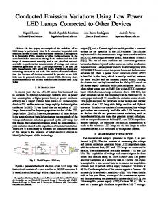
II- Review of previous 10-T 1-bit Adders Previous designs of 10-T adder are used in this paper for comparison purposes (Figure 1). The SERF adder [3], the Yuke Wang’s three 10-T adders (named: 9A, 9B, and 13A) [1], and Junming’s 10-T 1-bit adder [4]. They all suffer from 2VT loss of the output voltage levels for certain input signals sets. This was not critical for 0.35µm and older CMOS technologies. However, for the 0.18 µm and subsequent CMOS technologies, the proper operation of these adder designs is not possible including their use in n-bit adders. The voltage level degradation (VT loss) occurs when either the PMOS transistor is passing logic “0” (VTP loss) or the NMOS transistor is passing logic “1” (VTN loss). Fig. 1 shows some of existing 10T adders with the input signals set that causes 2VT loss of its output signal.
1731
(a) SERF Adder
III- Two 10-T Full-bit adder with minimum degradation of its output voltage level
(b) Yuke-Wang-9A adder
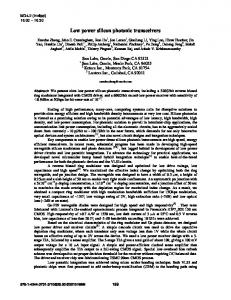
Two designs of 10-T full adder, with only one VT loss of the output voltage levels, are described and simulated in this paper. The critical part of the design is having a full swing XOR or XNOR gate in the first module to design the rest of the 1-bit adder with multiplexers to generate the COUT and SUM outputs with improved voltage levels (Figure 2). To generate a full swing XOR gate signal in n-10T adder (fig. 2a), an inverter is used. The XOR-gate output and CIN input signals, both with full voltage swing, will be used as control signals in the following multiplexer stages to generate COUT and SUM outputs with a maximum of one VT loss. Similarly, an inverter is used in the second design (fig. 2b). The Power dissipation of the two 10-T adders may further be reduced if the leakage current of the inverter is suppressed or decreased. The output signal of XOR gate, for the P-10T adder, is |VTP| for a specific input signals set (A=B=0). This causes the NMOS transistor of the inverter not to be completely turned off, giving rise to an unwanted leakage current and higher power dissipation. This also applies to the N-10T transistor when the input signals A and B are high. This problem is illustrated in Figure 3.
(c) Yuke-Wang-9B adder
(a) The N-10T 1-bit Adder
(d) Yuke-Wang-13A” adder
(e) Junming adder
(b) The P-10T 1-bit Adder
Fig. 1: Five previous 10-Transistors (10-T) fulladders showing the wrest output voltages.
Fig. 2: Two 10-T Adders with one VT loss.
1732
Table 1: Simulation results of the adder designs Frequency 100 MHz P-10T N-10T P-11T N-11T CMOS 28T TGA 20T
Fig. 3: The inverter leakage current for specific input signals Sizing the transistors to have a skewed inverter, such that the switching voltage (VS) of the inverter in the P-10T adder is higher than 0.5 VDD, while it is lower in the N-10T adder. Furthermore, adding a narrow series-connected transistor to the inverter decreases the leakage current. (This technique is targeting the 0.13µm and subsequent CMOS technologies to reduce static power dissipation). This transistor is an NMOS for P-10T adder and a PMOS for N-10T adder. Figure 4 shows adding the series-connected transistor to the inverter. The inverter, used in the P-10T adder, may have an input of VTP in the worst case. This makes the n-MOS transistor not completely off. With sizing (WN =300nm, WP = 900nm) of the inverter transistors, the switching voltage is changed to VS=0.86V. Adding an n-MOS stack transistor, the switching voltage further increases to Vs=0.97V. For the N-10T adder, the input of its inverter degrades to VDD- VTN in the worse case. This makes the p-MOS transistor not completely off. With sizing (WN=600nm, WP = 300nm), the switching voltage decreases to Vs= 0.67V. Adding a p-MOS stack transistor, Vs further decreases to 0.63V. The power dissipation and the time delay of the two sized 10-T adders, the two adders with an extra transistor, CMOS (28T), and Transmission Gate Adder (TGA 20T) are simulated. The maximum frequency of input signals is 100MHz. The simulation results, in Table 1, show that both the power consumption and the Time delay of both P-10T and P-11T are higher than those of N-10T and N-11T. Therefore, we use N10T adder in the n-bit adders and the modified N-12T adder in the array multiplier as described in the next sections.
Power [µW] 20.9 9.94 15.56 9.17 17.65 12.19
td (SUM) [ps] 792 566 814 574 307 215
td (COUT) [ps] 629 598 544 606 222 263
IV- n-bit Adders One of the advantages of N-10T adder is that it can operate properly even when one of the inputs of XNOR gate has one VT loss. By applying the signal with one VT loss to input B, fig. 2, the VT loss does not propagate to the output of the adder, and consequently does not accumulate when used in n-bit Adders. The wave shown in figure 5 illustrates the full swing wave, called “A” [0, VDD], and the wave with one VT loss, called “B” [VTP, VDD- VTN], can be added together in the N10T adder. The output of XOR, after the inverter, is not affected by the VT loss of one of its two inputs. The input B, in the simulation, varied from 0.6 V to 1.2V representing the threshold-voltage loss of the signal level. However, this is quite larger than the value of the thresholdvoltage with no body effect (VTN0 = 0.487V) in 0.18 µm CMOS technology. These values reflect the voltage levels obtained from the circuit simulation. This is due to the high body effect of the transistors. The VT loss can be reduced by using lower VT and/or lower-body-effect transistors, if accommodated by the adopted CMOS technology.
Fig. 4: Addition of a narrow Transistor to decrease the leakage current in an inverter (Stack Transistor).
1733
Fig. 5: Full swing of the output voltage of the XOR gate used in the N-10T adder and the correct operation of the 1-bit adder.
Therefore, the described N-10T design can be used in n-bit RCA and CSA Adders [5] if the carry-out (COUT) of previous adder is applied at input B. However, this is not desirable for RCA adders since the path of the propagation of the carry signal is made longer. All the inputs signals are applied through buffers and have been fed into the adder cells, while all the outputs are loaded with buffer circuits. The power consumption and maximum time-delay values of the 4-bit and 12-bit adders are shown in Table 3. The simulation was carried out at a frequency of 50MHz for the 4-bit RCA and the 12-Bit CSA.
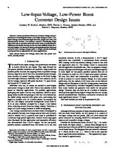
V- The 12-T 1-bit Adder and Array Multiplier Previous 12-T adders [2] do not operate correctly when used in a multiplier due to accumulation of VT loss, causing erroneous or ambiguous output logic value. Here we present a solution by modifying the design of the 10-T adders. One of the adder two outputs must have full voltage swing while the other can have a maximum of one VT loss. Adding two transistors to the multiplexer, used to generate COUT, in the 10T adders, allows a full voltage swing of COUT. This increases the number of transistors of the improved adder to 12 (fig. 6). The 4x4 multiplier employs AND gates and an array of 12T 1-bit adders to generate the final result [5-6]. The simulation is performed at a frequency of 50 MHz, for 0.18µm CMOS technology. The results are presented in Table 2 and some of the Output waves with one input wave are shown in figure 7.
Fig. 7: One set of selected input (A) and output (P3-P7) pulses from the simulation of the 4x4 Array Multiplier.
VI- Conclusion Minimum-Number-Transistor adders and multiplier which have up to one VT loss at their output signals are described in this paper. Two n-bit adders and one array-multiplier, with acceptable operation, were designed and simulated using the lowest-number-of-transistors (10-T and 12-T) full adders. Challenges in lowering the power dissipation and further reducing the VT losses can be solved in 0.13µm and subsequent CMOS technologies where multi VT devices are provided. MOSFET Transistors with lower body effect will also reduce the VT losses.
Acknowledgments This work was partially supported by Natural Sciences and Engineering Research Council of Canada (NSERC).
References [1] Yuke Wang et al, ”Design and analysis of low-power 10-transistor full adders using novel XOR-XNOR gates”, IEEE Trans. on Circuits and Systems II: Analog and Digital Signal Processing, Vol. 49, No 1, pp. 25–30, 2002.
Fig. 6: N-12T Adder: Adding 2 transistors, to the N-10T design, to remove the VT-loss of the output signal COUT. Table 2: Simulation results of a 4-bit RCA adder, a 12-bit CSA adder, and an array multiplier
[2] Wang, Y. et al, “A Novel Multiplexer-Based Low-Power Full Adder“, IEEE Trans. on Circuits and System —II, Vol. 51, No 7, pp. 345–348, 2004. [3] Shalem, R. et al, “A novel low power energy recovery full adder cell“; Proc. Ninth Great Lakes Symposium on VLSI, pp. 380 383, 1999. [4] Lu Junming, ”A novel 10-transistor low-power high-speed full adder cell”; Proc. 6th International Conf. on Solid-State and Integrated-Circuit Technology, 2001, Vol. 2, pp. 1155 – 1158, 2001.
n-bit adder, multiplier
The used 1-bit adder
Power [µW]
Time Delay [ns]
4-bit RCA
N-10T
34.28
3.103
12-bit CSA
N-10T
90.14
5.28
[5] Weste, N. et al, “CMOS VLSI design: A circuit and system perspective”, Addison-Wesley, 3rd Edition, 2004.
4×4 Array Multiplier
N-12T
145.48
3.97
[6] Bellaouar, A, Elmasry, M.; “Low-Power Digital VLSI Design Circuits and Systems” Kluwer Academic Publishers, 1995.
1734