N02-367
2008 IEEE Nuclear Science Symposium Conference Record
Low-power Wide-dynamic-range Readout System for a 64-channel Multi-anode PMT of a Scintillation Gamma Camera H. Kubo, K. Hattori, C. Ida, S. Iwaki, S. Kabuki, S. Kubo, S. Kurosawa, K. Miuchi, H. Nishimura, Y. Okada, A. Takada, M. Takahashi, T. Tanimori, K. Tsuchiya, and K. Ueno Abstract-We have developed a low-power wide-dynamicrange readout system for a 64-channel multi-anode photomultiplier (PMT) of a scintillation gamma camera. Each anode is individually read with the system that contains discrete devices of amplifiers, comparators, sample-hold ADCs, and FPGAs. The size of the system which is designed for a twodimensional array of Hamamatsu flat panel PMT 88500 is 5x5x14 cm3. The input dynamic range is variable by replacing the feedback capacitor of the preamplifier (e.g., 700 pC and 4000 pC for GSO(Ce) and LaBr3(Ce) crystals, respectively). The serialized ADC data are sent to a VME sequence module. The total power consumption is 1.6 W per 64 channels. With this system we have developed a gamma camera using an 8x8 array of GSO(Ce) pixels with a pixel size of 6x6x13 mm3 coupled to an H8500, and obtained flood-field irradiation images at energies from 30 keV to 1.3 MeV. The energy resolution was 10.8±0.4 % (FWHM) at 662 keV. In addition, we used the readout system for an 8x8 array of LaBr3(Ce) pixels with a pixel size of 6x6x15 mm 3 and obtained a flood-field irradiation image at 662 keV.
I.
of each photon can be determined in a reduced small arc. The scattering angle qJ is obtained from
me c 2 Ee ., (1 ) Ee + Ey Ey where Ee and Eyare energies of the recoil electron and the scattered gamma ray, respectively, me is the electron mass and cos qJ = 1-
c is the light speed. Therefore a scintillation camera with a higher energy resolution leads to a higher angular resolution of a Compton camera. Since a scintillator with a high energy resolution tends to have a higher light yield, a readout system for the scintillation camera needs to have a wide dynamicrange for an input signal. In addition, especially in a balloonborne experiment, the power consumption of the readout system is severely restricted.
INTRODUCTION
W
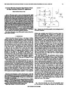
e have been developing a Compton gamma camera for applications to a balloon-borne astronomical experiment [I], [2] and nuclear medicine [3]-[5]. It is a hybrid detector of a gaseous time projection chamber (fl- TPC) and a positionsensitive scintillation camera enclosing the fl-TPC as shown in Fig. 1 [6], [7]. The fl-TPC measures both the threedimensional fine tracks of a Compton-recoil electron with a resolution of sub-millimeter and the energy by electrodes on the micro pixel gas chamber (fl-P1C) [8]-[10]. The scintillation camera measures the energy and position of a scattered gamma ray. By combining these measurements, full reconstruction of the Compton process for an incident gamma ray can be realized event by event, and the incident direction This work is supported by a Grant-in-Aid in Scientific Research of the Japan Ministry of Education, Culture, Sports, Science and Technology (MEXT), SENTAN of Japan Science and Technology Agency, and a Grantin-Aid for the Global COE program "The Next Generation of Physics, Spun from Universality and Emergence" from MEXT of Japan. H. Kubo, K. Hattori, C. Ida, S. Iwaki, S. Kabuki, S. Kurosawa, K. Miuchi, H. Nishimura, Y. Okada, M. Takahashi, T. Tanimori, K. Tsuchiya, K. Ueno are with Department of Physics, Graduate School of Science, Kyoto University, Kitashirakawa-Oiwake, Sakyo-ku, Kyoto 606-8502, Japan. (email:
[email protected]) S. Kubo is with ClearPulse Co., 6-25-17 Chuo, Ohta-ku, Tokyo 143-0024, Japan. A. Takada is with Scientific Balloon Laboratory, ISAS, JAXA, Yoshinodai 3-1-1, Sagamihara, Kanagawa 229-8510, Japan
978-1-4244-2715-4/08/$25.00 ©2008 IEEE
Scintillator
Fig. 1. Conceptual stnlcture of the sub-MeV/MeV gamma-ray imaging detector capable of three dimensional tracking of a Compton-recoil electron.
In our previous work, we first developed gamma cameras based on an 8x8 array of CsI(TI) pixels with a pixel size of 6x6x20 mm 3 [11], an 8x8 array of GSO(Ce) pixels with a pixel size of6x6xl3 mm 3 [12], [13], a 64-channel multi-anode photomultiplier (PMT) (Hamamatsu flat-panel H8500), a readout system using discrete devices of amplifiers, comparators, and peak-hold ADCs without any ASIC, and a resistor-chain between anodes for reducing the number of readout channels to save the power consumption, in which each anode was connected to resistors in order to read four channels at the comers and obtain a two dimensional position in the charge-division method. The GSO(Ce) scintillation camera, using this system with resistor chains connecting 192 anodes of three PMTs, had an incident-energy dynamic range of 80-800 keY, a typical energy resolution of 11% (FWHM) at 662 keY, and a power consumption of 2.7W per 64 anodes.
1181
Since our developed Compton camera with a detection volume of 30x30x30 cm3 has more than 2000 anodes of PMTs, the power consumption needs to be reduced. We next developed gamma cameras using commercial lowpower ASIC chips (IDEAS VA32HDRI4, VA32HDRII, TA32CG2) to read anodes individually, which contains preamplifiers, shapers, sample-holds, multiplexers, fast shapers, and comparators [11], [13]. The GSO(Ce) scintillation camera with this system had an incident energy dynamic range of 100-700 keY and a typical energy resolution of 13% (FWHM) at 662 keY, which were worse than those using discrete devices and resistor chains. This is because the input dynamic ranges of the ASICs we used were so narrow that the H8500 should be operated with a low gain under a low applied voltage in order to measure 662 keY gamma rays. We therefore developed a board connecting an attenuation resistor between an input of the ASIC (IDEAS VA32HDRII) and the ground in order to operate the H8500 with the typical gain. The GSO(Ce) scintillation camera with the attenuator board had an incident energy dynamic range of 30-900 keV and a typical energy resolution of 11.7% (FWHM) at 662 keY. The power consumption of the system is 1.4 W per 64 anodes, which is half of that using discrete devices and resistor chains. In order to improve an angular resolution of our Compton camera, we have developed an 8x8 array of LaBr3(Ce) pixels, which has higher light output and higher energy resolution than other scintillators [14]. The attenuator board connected to an ASIC is available for various scintillators with different light yields. However, the attenuation worsens a signal to noise ratio. We therefore have developed a PMT readout system using discrete devices with a wide input-dynamicrange and a lower power-consumption than the previous systems. In this paper, we report the readout system and the performance of a scintillation camera using the system. II. READOUT SYSTEM
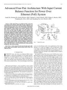
A. Circuit Architecture Figure 2 shows a block diagram of the developed system, which individually reads anodes of a 64-channel multi-anode PMT. Each anode signal is inputted to a preamplifier, a shaper, and a 12-bit sample-hold ADC. The output of the preamplifier is also inputted to a fast shaper and a comparator generating a trigger signal for the sample-hold. In addition, a trigger from the external input on the rear panel is available. The ADC data is serialized and sent by FPGAs to a VME-6U sequence module (CP80057) shown in Fig. 3 via an Ethernet cable in the LVDS level. The CP80057 can deal with four readout systems (CP80 190) shown in Fig. 4. It takes 20 f.1s to process one event (64 channels). The size of the system which is designed for two-dimensional array of H8500 is 52x52x136 mm3 (Fig. 4). Since power consumptions of systems shown in Fig. 3 and Fig. 4 are 1.5 W and 1.2 W, respectively, the total power consumption of systems is 1.6 W per 64 channels.
Data Processor VME6U module
L
~~·64 ~
- - - - - - - - - -........-
......-'Triggerout
Fig. 2. Block diagram of the readout system for a 64-channel multi-anode PMT.
Fig. 3. (left) Sequence module on a VME-6U bus (CP80057). (right) The CP80057 is connected to the CP80190 with an Ethernet cable.
Fig. 4. Photograph of the readout system (CP80190) which contains preamplifiers, shapers, sample-hold ADCs, FPGAs. An H8500 is connected to the four connectors shown on the left in the top figure. A power supply cable and a data communication cable are connected to connectors on the rear panel shown in the bottom right figure.
B. Dynamic Range and Linearity The input dynamic range of the readout system is variable by replacing the SMD feedback capacitor of the preamplifier. We adopted the capacitors of 330 pF (Type-I readout system) and 1800 pF (Type-II readout system) for GSO(Ce) and LaBr3(Ce) crystals, respectively. Figure 5 shows a waveform of the output from the shaper in the Type-I readout system when a test pulse with 100 pC was inputted. The peaking time is 5 f.1s.
Fig. 5. Waveform of the output from the shaper in the Type-I readout system to an input of a test pulse with 100 pC, shown in 50mV/div and 4 Jls/div.
1182
Figures 6 and 7 show ADC values of the two readout systems (Type-I, Type-II) for test pulse inputs. The dynamic ranges of Type-I and Type-II were 700 pC and 4000 pC, respectively. In Figs. 6 and 7, residuals from the fitted line are also shown. The residuals of Type-I and Type-II were more than 2 % below 50 pC and 750 pC, respectively.
Fig. 10. Scintillation camera consisting of a scintillator pixel array, an H8500, and the readout system CP80I90.
IV. PERFORMANCE OF SCINTILLATION CAMERA
....."J iii
i ~t
A. GSO(Ce) scintillation camera with the Type-/ readout Gamma rays from a 137CS source were irradiated to the 6 GSO(Ce) scintillation camera with a PMT gain of I.7x 10 attached to the Type-I readout system. The reconstructed image is shown in Fig. II. Each pixel is clearly separated as shown in Fig. 11. The energy spectrum is shown in Fig. 12 with those for 133Ba and 60Co sources. The energy dynamic range was from 30 keV to 1.3 MeV, which was wider than that taken with the readout system using ASICs and attenuators. Figure 13 shows energy resolutions. The best-fit line is represented by (10.8±0.4)x(E/662keVro. 44±0.03 % (FWHM), which was better than that taken with the readout system using ASICs and attenuators.
_
~~""""'-_.1tI
C:-./PCI
Fig. 6. ADC values (top) and residuals from the fitted line (bottom) with the Type-I readout system.
E
:r---------------
~ '-~
~t -r
~~
~
~
~O~1·..7..;.··1·.:..;.·'~·J' ..... ....., ....... _v ··~· --' i;OOC~~J
l~tL~'~~ I~:~:.
_1. " 2iiOO."
.· · . ·· ·•
0.8....-------------~·-
.....
o.el
- 'I
o.• ~
1#
· .. . ·
·
G.2t-oft G -o.2l'.....---...,;;;:....-----. •I
.....
Fig. 7. ADC values (top) and residuals from the fitted line (bottom) with the Type-II readout system.
-o··f
~··t -O·.fuI
III. SCINTILLATION CAMERA Figure 8 shows an H8500 and an 8x8 array of GSO(Ce) pixels with a pixel size of 6x6x13 mm 3 [12]. Figure 9 shows an 8x8 array of LaBr3(Ce) pixels with a pixel size of 6x6xl5 mm 3 [14]. The array was coupled to the H8500 with optical grease, and then the H8500 was attached to the readout system as shown in Fig. 10.
·
·. .
100
I. II
., 20
-4~&....L:o... .L~~-" ~," O~LL~fi"-L.oj~- 0.8 0
J oJ -- -J ~ J 8..
0.8
" •.•
Fig. 11. (top) Reconstructed image taken with the GSO(Ce) scintillation camera attached to the Type-I readout system in flood-field irradiation of gamma rays from a 137 Cs source. (bottom) Profile for the row of the array enclosed by the red square in the top figure.
-, f
tl8lO,--------------·------,
60(0
137Cs I
::~Ll
Fig. 8. 64ch multi-anode PMT (Hamamatsu H8500) (left) and 8x8 array of GSO(Ce) scintillator pixels ri ht .
E.....,p-VJ
133Ba
Fig. 9. Photograph of an 8x8 array of LaBr3(Ce) pixels in a hermetically sealed package.
Fig. 12. Energy spectra with the pixel, enclosed by the green circle in Fig. 11, of the GSO(Ce) scintillation camera attached to the Type-I readollt system for 137CS (top left), 60Co (top right), and 133Ba (bottom) sources.
1183
i~
--------------
with a resistor-chain between anodes and the Type-I readout system shown in 16 and 17.
10
30 ... 50
1r
2X1r
1!...,Jt0luVJ
Fig. 13. Energy resolutions of the GSO(Ce) scintillation camera attached to the Type-I readout system.
B. LaBr3(Ce) scintillation camera with the Type-II readout Gamma rays from a 137Cs source were irradiated to the LaBr3(Ce) scintillation camera with a PMT gain of 1.4xl06 attached to the Type-II readout system. The reconstructed image is shown in Fig. 14. The energy spectrum is shown in Fig. 15. The energy resolution at 662 keY is 5.4±0.4% (FWHM), which was comparable to that in our previous work [14] using a readout system with standard discrete devices and a resistor-chain between anodes. However, there is a highenergy tail around 700-800 keV, probably due to non-linearity of the Type-II readout system. We need to improve the linearity in order to obtain the intrinsic performance of the LaBr3(Ce) crystal. 0.' 0.6
0." 0.2 -0
-o.2l
-. .
0...· ·__...
,poo-_ _.._ · ......
1_-
-0.4 ... -0.6
/I
90
..
•
80'
70
eo 50
1
....
1
30 20
•
"
L
'!t
Type-I readout system chI
eM ehS eh8
ch61 eh64 Fig.I7. Diagram of the GSO(Ce) scintillation camera with an anoderesistor-chain and the Type-I readout system.
Gamma rays from a 137Cs source were irradiated to the GSO(Ce) scintillation camera with a PMT gain of 2.1xI0 6 • The reconstructed image is shown in Fig. 18. The energy spectrum is shown in Fig. 19 with those for 133Ba and 54Mn sources. The energy dynamic range was from 80 keV to 800 keV, which was narrower than that without an anode-resistorchain. Figure 20 shows energy resolutions. The best-fit line is represented by (10.6±0.5)x(E/662keVro,44±o.o4 % (FWHM), which was comparable to that without an anode-resistor-chain. The total power consumption of the system was 0.1 W per 64 anodes, which was one sixteenth of that without an anoderesistor-chain.
100
. .. . . . . . .. .. . . '
Fig. 16. view of the resistor-chain between PMT anodes. Four channels at the comers, "a" to "d", were read.
.10
l
0.8-
Fig. 14. (top) Reconstructed image taken with the LaBr3(Ce) scintillation camera attached to the Type-II readout system in flood-field irradiation of gamma rays from a 137Cs source. (bottom) Profile for the row of the array enclosed by the red square in the top figure.
-0-
1__ .-
-o.2~
-0."
-
-0.6 -0.8::" - l..
1
-I..
.-
1 ..
i
1j
..
j ~
-0.8 -0.6 -0.4 -0.2
00
101
200
300
401
500
"'
Teo
70
--
0.2-
137C5
..... ·· .• .• •....• . .. · .. ·• .G> • • • • -I • ·• • •• •• •• ...
'
0.10.4-
0.0..
A
l _
-0
I
1 ..
0.2
J.
.1
1
J.
0.4
I
J.
~
50
30
20 10
J
0.6
800 Mel 1001 ElHIf'IY'lk.Vj
Fig. 15. Energy spectrum with the pixel, enclosed by the green circle in Fig. 14, of the LaBr3(Ce) scintillation camera attached to the Type-II readout system for a 137CS source.
C. GSO(Ce) scintillation camera with an anode-resistorchain and the Type-I readout
In order to reduce further the power consumption, we investigated the performance of GSO(Ce) scintillation camera
Fig. 18. (top) Reconstructed image taken with the GSO(Ce) scintillation camera with an anode-resistor-chain attached to the Type-I readout system in flood-field irradiation of gamma rays from a 137CS source. (bottom) Profile for the row of the array enclosed by the red square in the top figure.
1184
..
-
--------------,
[2]
54Mn
[3] [4] [5]
133Ba
[6]
..- ..-.--~~. . ii1.....,il..._.w...oii. ..
[7]
......,1UYl
lOt
Fig. 19. Energy spectra with the pixel, enclosed by the green circle in Fig. 18, of the GSO(Ce) scintillation camera with an anode-resistor-chain attached to the Type-I readout system for 137CS (top left), 54Mn (top right), and mBa (bottom) sources.
i~f
[9] [10] [11]
't_.. , eo
[8]
7110
[12]
1et
[13]
Energy(keVJ
Fig. 20. Energy resolutions of the GSO(Ce) scintillation camera with an anode-resistor-chain attached to the Type-I readout system.
[14]
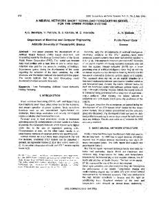
V. CONCLUSION We have developed a low-power wide-dynamic-range readout system which individually reads every anode of a 64channel multi-anode PMT (Hamamatsu flat panel H8500) of a scintillation gamma camera. The system contains discrete devices of amplifiers, comparators, sample-hold ADCs, and FPGAs. The total power consumption is 1.6 W per 64 channels. The input dynamic range is variable by replacing the feedback capacitor of the preamplifier (700 pC and 4000 pC for GSO(Ce) and LaBr3(Ce) crystals, respectively). With this system we have developed a gamma camera using an 8x8 array of GSO(Ce) pixels with a pixel size of 6x6xl3 mm 3 coupled to an H8500, and obtained flood-field irradiation images at energies from 30 keY to 1.3 MeV. The energy resolution was 10.8±0.4% (FWHM) at 662 keY. We further investigated the performance of GSO(Ce) scintillation camera with a resistor-chain between anodes and the readout system. Although the energy dynamic range of 80-800 keV was narrower~ the total power consumption was reduced to 0.1 W per 64 anodes. In addition, we used the readout system for an 8x8 array of LaBr3(Ce) pixels with a pixel size of 6x6xl5 mm 3 • The energy resolution of a LaBr3(Ce) pixel is 5.4±0.4% (FWHM) at 662 keY. However, there is a high-energy tail in the energy spectrum probably due to non-linearity of the readout system. We need to improve the linearity of the readout system in order to obtain the intrinsic performance of the LaBr3(Ce) crystal. REFERENCES [1]
A. Takada, et aI., "Observation of diffuse gamma-ray with electrontracking Compton imaging camera loaded on balloon", 2007 IEEE NSS.Conf Rec., pp.2558-2563.
1185
K. Ueno, et aI., "Compton hnaging Camera Using an Electron-Tracking Gaseous TPC and a Scintillation Camera", 2008 IEEE NSS, N65-8. S. Kabuki, et aI., "Diagnostic Approach of Using an Electron tracking Compton Gamma-Ray Camera Based on Small Animal and Phantom Experiments", 2007 IEEE MIC Conf. Rec., pp.3395-3399. S. Kabuki, et aI., "Simultaneous hnaging of Multi Nuclides Using the Electron Tracking Compton Gamma-Ray Camera Based on Small Animal and Phantom Experiments", 2008 IEEE MIC, M06-I99. 1. Tanimori, et aI., "Development of Electron Tracking Compton Camera Based on Micro Pixel Gas Detector and Its Application for Medical hnaging", 2008 IEEE NSS Compton Camera Workshop,CC2-I. R. Orito, et aI., '"A novel design of the MeV gamma-ray imaging detector with Micro-TPC", Nucl. Ins/r. and Me/h. A., vol. 513, pp.408412,2003. 1. Tanimori, et aI., "MeV y-ray imaging detector with micro-TPC", New Astron. Rev., vol. 48, pp. 263-268,2004. A. Ochi, et aI., "A new design of the gaseous imaging detector: Micro Pixel Chamber", Nucl. Instr. andMeth. A., vol. 471, pp.264-267, 2001. H. Kubo, et aI., "Development of a time projection chamber with micropixel electrodes", Nucl. Ins/r. and Meth. A., vol. 513, pp.94-98, 2003. K. Miuchi, et aI., "Performance of a time-projection chamber with a large-area micro-pixel-chamber readout", Nucl. Ins/r. and Meth. A., vol. 576, pp.43-46, 2007. H. Sekiya, et aI., "Studies of the performance of different front-end systems for flat-panel multi-anode PMTs with CsI(Tl) scintillator arrays", Nucl. Instr. and Mefh. A., vol. 563, pp.49-53, 2006. H. Nishimura, et aI., "Development of large area gamma-ray camera with GSO(Ce) scintillator arrays and PSPMTs", Nucl. Instr. and Meth. A., vol. 573, pp.II5-II8, 2007. K. Ueno, et aI., "Performance of the gamma-ray camera based on GSO(Ce) scintillator array and PSPMT with the ASIC readout system", Nucl. Instr. andMeth. A., vol. 591, pp.268-271, 2008. H. Kubo, et aI., "Development of a Gamma Camera Based on an 8x8 Array of LaBr3(Ce) Scintillator Pixels Coupled to a 64-Channel MultiAnode PMT", 2007 IEEE NSS Conf. Rec., pp.4569-4573.