Zhiyong He, Sébastien Roy, and Paul Fortier. Department ..... Jean-Yves Chouinard for his helpful ... [8] Z. He, P. Fortier, and S. Roy, âA class of irregular LDPC.
This full text paper was peer reviewed at the direction of IEEE Communications Society subject matter experts for publication in the ICC 2007 proceedings.
Lowering error floor of LDPC codes using a joint row-column decoding algorithm Zhiyong He, Sébastien Roy, and Paul Fortier Department of Electrical and Computer Engineering, Laval University Quebec City, Québec, Canada, G1K 7P4 ABSTRACT Low-density parity-check codes using the beliefpropagation decoding algorithm tend to exhibit a high error floor in the bit error rate curves, when some problematic graphical structures, such as the so-called trapping sets, exist in the corresponding Tanner graph. This paper presents a joint row-column decoding algorithm to lower the error floor, in which the column processing is combined with the processing of each row. By gradually updating the pseudo-posterior probabilities of all bit nodes, the proposed algorithm minimizes the propagation of erroneous information from trapping sets into the whole graph. The simulation indicates that the proposed joint decoding algorithm improves the performance in the waterfall region and lowers the error floor. Implementation results into field programmable gate array (FPGA) devices indicate that the proposed joint decoder increases the decoding speed by a factor of eight, compared to the traditional decoder. I. INTRODUCTION Low-density parity-check (LDPC) codes introduced by Gallager [1] have recently received a lot of interest, because they allow transmission of data at rates near the channel capacity with low probability of error. For many practical applications, including Gigabit Ethernet, longhaul optical channels, data storage and deep-space communication systems, one requires extremely reliable transmission with relatively low bit-error rates (BER), such as below 10-10. Though the BER of LDPC codes decreases steeply with increasing signal-to-noise ratio (SNR) for low SNR, the BER tends to exhibit a sudden saturation for medium to high SNR, i.e. the so-called error floor. It is accepted now that the error floor of LDPC codes using the Belief-Propagation (BP) decoding algorithm is mainly due to some problematic graphical structures in the code’s Tanner graph, such as trapping sets [2]- [4]. The concept of a trapping set, initially referred to as a nearcodeword, was first described in the analysis of error floors in [2] and was further described in [3]. Some nearcodewords which do not constitute valid codewords but cause failures in the BP decoder in an AWGN channel or in a binary symmetric channel are typically referred to as
trapping sets. Essentially, a (b, c) trapping set is a subset of b bit nodes, for which the induced subgraph contains c check nodes of odd degrees, where a bit node and a check node correspond to a column and a row in H, respectively. To lower the error floor, LDPC codes have carefully been constructed with some constraints in the design of the parity-check matrix (e.g. [5]-[8]). On the other hand, for practical application in industrial standards, LDPC codes have to be designed to satisfy the specifications of various standards. For example, the LDPC codes specified in the IEEE 802.16e standard for fixed and mobile broadband wireless access systems flexibly support different frame lengths through the use of an expansion factor which is the size of each submatrix [9]. Since the same set of parity-check matrices is used for various frame lengths, it is difficult to avoid all the problematic trapping sets in the code construction. Thus, robust decoders which minimize the negative influence of trapping sets on the BER performance are favored to lower the error floor. In this paper, we propose an efficient decoding algorithm to lower the error floor of various LDPC codes. The basic idea of the proposed algorithm is to minimize the error spread from the trapping sets to the whole graph, by gradually updating the pseudo-posterior probabilities of all bit nodes and the extrinsic messages. The simulation results indicate that the proposed decoding algorithm dramatically improves the BER performance in both the waterfall and the error floor regions, with respect to the traditional decoder. II. BELIEF PROPAGATION DECODING LDPC codes can be effectively decoded using the belief propagation (BP) algorithm which is also variously designated as the message-passing algorithm and the sumproduct algorithm. Prior to discussing the proposed decoding algorithm in the next section, it is useful to review related work in this section. A. Traditional decoder based on BP algorithm Let H be an m×n parity check matrix which consists of m rows and n columns, and hij be the entry of H at position (i, j). Thus, the Tanner bipartite graph which describes the parity-check matrix consists of m check
1-4244-0353-7/07/$25.00 ©2007 IEEE
This full text paper was peer reviewed at the direction of IEEE Communications Society subject matter experts for publication in the ICC 2007 proceedings.
nodes and n bit nodes. Denote the set of bit nodes neighboring a check node i by N (i ) ≡ { j : hij = 1} . Similarly, denote the set of check nodes neighboring a bit node j by M ( j ) ≡ {i : hij = 1} . The notation M(j)\i is the set M(j) excluding the check node i, and the notation N(i)\j is the set N(i) excluding the bit node j. The BP decoding algorithm performs two separate processing. In the first phase for row processing, the extrinsic messages in m check nodes are calculated as follows:
rij0 =
1 1 (1 − 2qik1 ) , + ∏ 2 2 k∈N ( i )\ j
rij1 = 1 − rij0 .
∏
rkj1 ,
qij0 = K ij (1 − p1j )
∏
(3) (4)
1
qij + qij = 1 . Then, the pseudo-posterior probabilities of n
bit nodes are updated:
∏
rkj1 ,
∏
rkj0 ,
to check nodes which implement (1) for row processing in the next iteration. Though the averaged BP algorithm lowers the error floor, it increases the number of iterations required for decoder convergence with respect to the traditional BP algorithm. D. Scaled decoder based on log-BP algorithm The scaled decoder proposed in [11] is implemented in the same way as the traditional decoder based on log-BP algorithm, except that either the extrinsic messages vij in
(6)
a coefficient, η ∈ [0,1] . Just like the averaged decoder, it was observed that the reduction of the error floor level came at the expense of decreased convergence rate.
where the constants Kj are chosen to ensure that
Q 0j + Q1j = 1 .
III. JOINT ROW-COLUMN DECODING ALGORITHM
B. Traditional decoder based on log-BP algorithm To achieve hardware implementation of decoders, the BP algorithm is generally implemented in the logarithmic domain, thus resulting in the so-called log-BP algorithm. In this BP variant, the extrinsic messages in the first phase for row processing are calculated as follows:
∏
1
(7) or the extrinsic messages uij in (9) are scaled down by
k ∈M ( j )
vij =
t
(5)
k ∈M ( j )
Q 0j = K j (1 − p1j )
1
where t ≤ l . Then, the averaged messages qij (l ) are sent
where the constants Kij are chosen to ensure that
Q1j = K j p1j
in (3) are averaged over t iterations according to:
(2)
k ∈M ( j )\ i 0
1
algorithm, the extrinsic messages qij at the l-th iteration
q1ij (l ) = [ qij1 (l ) + q1ij (l − 1) + ... + q1ij (l − t + 1)] (10)
k ∈M ( j )\ i
rkj0 ,
It was conjectured that a possible indicator of the emergence of error traps may be a sudden magnitude change in the values of certain extrinsic messages in bit nodes [10]. To prevent erroneous information from being "trapped" in the code graph, an averaged BP decoding algorithm was proposed in [10]. Under the averaged BP
(1)
In the second phase for column processing, the extrinsic messages in n bit nodes are calculated as follows.
q1ij = K ij p1j
C. Averaged decoder based on BP algorithm
sign(uik )iφ[
k ∈N ( i )\ j
∑
φ (| uik |)] ,
(7)
k ∈N ( i )\ j
where φ ( x) = log((e + 1) /(e − 1)) . In the second phase for column processing, log-likelihood ratios of n bit nodes are calculated via: x
U j = llr ( j ) +
∑
x
vkj ,
(8)
k∈M ( j )
where the prior log-likelihood ratio of the j-th bit node
llr ( j ) = log( p 0j / p1j ) . Then, the extrinsic messages of n bit nodes are updated as follows:
uij = U j − vij
(9)
To lower the error floor caused by trapping sets, we propose an efficient approach to the protection against the propagation of erroneous information from trapping sets into the whole graph, by updating gradually the pseudoposterior probabilities of all bit nodes. In a traditional decoder which performs the separate row-column processing, the pseudo-posterior probabilities U j in (8) (or Q j in (5)) cannot be updated in the second phase for the column processing until all the extrinsic messages vij (or rij ) have been calculated in the first phase for row processing. Instead of the separate row-column processing, the proposed joint row-column processing incorporate the calculation of the pseudo-posterior probability in the column processing into the row processing. The loglikelihood ratio U j (or the pseudo-posterior probability
This full text paper was peer reviewed at the direction of IEEE Communications Society subject matter experts for publication in the ICC 2007 proceedings.
U ' j = uij + v "ij ,
Q j ) is immediately updated, once one of the extrinsic messages vij (or rij ) is calculated. Thus, the logc
likelihood ratio U j (or Q j ) is updated w j times at each c
iteration, where w j is the column degree of the j-th column. In the proposed decoding algorithm, a joint rowcolumn processor is used to process m rows from the uppermost row to the lowermost row in each iteration, while no column processor is required. For the irregular LDPC codes having non-constant degrees, it is suggested to rearrange the rows of the parity-check matrix in a degree-decreasing manner from top to bottom. Thus, the check nodes of high degrees are firstly processed, providing better information for the check nodes of low degrees. During the decoding period, the joint row-column processor reads both the log-likelihood ratio U j and the extrinsic messages vij , and then calculates a new loglikelihood ratio U ' j and new extrinsic messages v 'ij . Many algorithms, such as the BP algorithm, min-sum algorithm, or maximum a posteriori (MAP) algorithm, can be modified to implement a joint row-column processor. A. Joint processor based on log-BP algorithm A joint row-column processor based on the log-BP algorithm performs the following calculations for the i-th row with 1 ≤ i ≤ m .
uij = U j − vij , v 'ij =
∏
(11)
sign(uik )iφ [
∑
φ (| uik |)] ,
U ' j = uij + v 'ij , where
(12)
k ∈N ( i )\ j
k ∈N ( i )\ j
(13)
φ ( x ) = log((e + 1) /(e − 1)) . x
x
B. Joint processor based on min-sum algorithm As a simplified variant of the log-BP algorithm, the min-sum algorithm performs the summation of all extrinsic messages in each column and the minimization of all extrinsic messages in each row. A joint row-column processor based on the min-sum algorithm performs the minimization of the extrinsic messages in the i-th row with 1 ≤ i ≤ m .
uij = U j − vij , v 'ij =
∏
(14)
sign(uik )i min | uik | ,
k ∈N ( i )\ j
v "ij = α × v 'ij − β ,
k∈N ( i )\ j
(15) (16)
(17)
where α and β are two corrective factors with 0 < α < 1 . Since the log-likelihood ratio U j in either (13) or (17) is updated several times at each iteration, the extrinsic messages uij has to be re-calculated in (11) or (14) before it is used in the computation of the extrinsic messages v 'ij . After the m rows are processed, a hard decision is reached at each iteration according to the sign of U ' j . At the first iteration, the log-likelihood ratio U j and the extrinsic messages vij are set to be:
U j = log( p 0j / p1j ) ,
(18)
vij = 0 .
(19)
and
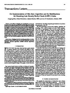
IV. PERFORMANCE ANALYSIS To evaluate the proposed decoder, we performed simulations for the LDPC codes specified in the IEEE 802.16e standard [9], assuming an AWGN channel and BPSK modulation. Due to the paper length constraint, the joint decoder based on the min-sum algorithm is not included in the following text. To exactly compare the difference between the traditional decoder and the proposed joint decoder, the received signals were sent to both decoders at the same time. A. Speed of convergence and number of iterations The bit error rate (BER) versus the number of iterations at a signal-noise-ratio per bit Eb /N0 = 2.5 dB for the LDPC code with a code length of 2304 and a code rate of 2/3 is compared in Fig. 1 for the traditional decoder based on the log-BP algorithm and the proposed joint decoder. The BER first decreases rapidly and eventually converges towards a value. It is clear that the joint decoder exhibits a much faster convergence behavior than the traditional decoder, because the latter updates the loglikelihood ratio value U j only once, while the former performs updates of U j
for several times at each
iteration. To attain a BER below 10−4, the traditional decoder needs 14 iterations, while the joint decoder needs only 7 iterations. Fig. 2 compares the BER obtained with the two decoders as a function of the number of iterations at Eb /N0 = 3 dB. To attain a BER below 10-6, the traditional decoder and the joint decoder need 11 and 6 iterations, respectively. The joint decoding algorithm dramatically reduces the number of iterations and increases the convergence rate of the decoding process. Since more
This full text paper was peer reviewed at the direction of IEEE Communications Society subject matter experts for publication in the ICC 2007 proceedings.
iterations result in a large decoding latency and low throughput, the maximum number of iterations in the hardware implementation described in the next section are set to be 10 and 20 for the joint decoder and the traditional decoder, respectively.
Fig. 1 BER of the LDPC code specified in the 802.16e standard with a code length of 2304 and a code rate of 2/3 versus the number of iterations at Eb /N0 = 2.5 dB under two decoding algorithms.
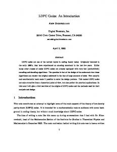
Fig. 2 Same as Fig. 1 but at Eb /N0 = 3 dB. B. Robustness to trapping sets To study the effect of trapping sets on the decoding reliability, the evolution of erroneous bits versus iterations was analyzed for all the simulated frames. In the several tens of millions frames, decision failures which were caused by trapping sets were observed. Fig. 3 shows the change in the number of erroneous bits in one frame as a function of the number of iterations for an LDPC code with a code length of 2304 and a code rate of 2/3 at Eb /N0 = 2.5 dB. Using the traditional decoder, the number of erroneous bits drops abruptly at first. However, after 15 iterations, the incorrect bit values of the bit nodes internal to the trapping set start to affect the decisions of the other
bit nodes. Errors spread from the trapping set to a large number of bit nodes between iterations 25 and 35. On the other hand, by using the proposed joint decoder, the number of erroneous bits drops even more suddenly at first, then converges to zero after 10 iterations. The spread of errors from the trapping set to the other bit nodes is minimized by updating gradually the pseudoposterior probabilities of all bit nodes several times during each iteration.
Fig. 3 Evolution of erroneous bits in a frame with trapping sets error at Eb /N0 = 2.5 dB.
Fig. 4 Evolution of erroneous bits in a frame with trapping set errors at Eb /N0 = 3 dB. Fig. 4 shows the evolution of erroneous bits in one frame versus the number of iterations for the LDPC code with a code length of 2304 and a code rate of 2/3 at Eb /N0 = 3 dB. After 10 iterations, the traditional decoding algorithm falls in a trapping set. Errors spread from the trapping set to a large number of bit nodes between iterations 15 and 22. Again, the proposed joint decoder demonstrates its robustness against trapping sets. C. Improvement in performance
This full text paper was peer reviewed at the direction of IEEE Communications Society subject matter experts for publication in the ICC 2007 proceedings.
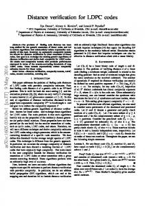
Both Fig. 1 and Fig. 2 have shown that the proposed joint decoder largely increases the convergence rate of the decoding process. Thus, at the same number of iteration, the joint decoder improves BER performance. As an example, the BER and frame-error-rate (FER) at the 10-th iteration versus Eb /N0 are compared in Fig. 5 for the two decoders. At the 10th iteration, the joint decoder decreases the BER from 10-5 to 10-6 at an Eb/N0 of 2.75 dB. On the other hand, to attain a BER below 10-6, a coding gain of 0.2 dB is observed for the joint decoder. Fig. 6 shows the BER and FER curves at the 50th iteration for the two decoders. An error floor occurs in the vicinity of 10−6 for the traditional decoder, while no error floor exists down to 10−8 for the joint decoder.
region at Eb / N 0 < 2.75 dB and the error floor region at Eb / N 0 ≥ 2.75 dB. The observation of the erroneous bits
caused by trapping sets at Eb / N 0 = 2.5 dB in Fig. 3 and at Eb / N 0 = 3 dB in Fig. 4 indicates that the problematic trapping sets not only result in error floors but also degrade the performance in the waterfall region.
V. DISCUSSION ABOUT HARDWARE IMPLEMENTATION To compare the decoding speed between the traditional decoding algorithm and the joint decoding algorithm, the two decoders for LDPC codes specified in the IEEE 802.16e standard with a frame length of 2304 and a code rate of 2/3 were implemented into Xilinx Virtex-4 Field Programmable Gate Array (FPGA) devices. The traditional log-BP decoder includes two processors: a row processor which performs the row processing in (7) and a column processor which updates the log-likelihood ratios in (8) and the extrinsic messages in (9). The function φ ( x ) = log((e + 1) /(e − 1)) in the row processor was implemented as a 6-bit Look-Up-Table (LUT). Without any column processor, the joint decoder includes only a joint row-column processor. Shown in Fig. 7 is an example of the joint row-column processor with 4 inputs and 4 outputs. The row processor shown in the figure performs exactly the same computation as the row processor in the traditional decoder. To reduce the propagation time from input signal to output signal in a row processor, a tree architecture is employed to implement the addition of extrinsic messages. By exploiting pipelining techniques, a maximum clock frequency of 365 MHz was achieved for the two decoders. Based on the synthesis and implementation reports of the Xilinx Integrated Software Environment (ISE) software, 7054 gates were required for implementing a row processor and a column processor. Since a column processor is not required in the proposed decoder, only 6825 gates are required for implementing a joint row-column processor, a 3% reduction in hardware cost. Since only one set of extrinsic messages are stored, the joint decoder reduces the memory requirement dramatically. Based on the results in Section IIIA, the maximum numbers of iterations were set to be 10 and 20 for the joint decoder and the traditional decoder, respectively. By assuming a decoding clock frequency of 300 MHz, the decoding speed of 11 Mbps can be achieved for the traditional decoder used for the LDPC code with a code length of 2304 and a code rate of 2/3, while the speed of the joint decoder reaches 90 Mbps. Thus the proposed joint row-column decoding algorithm increases decoding speed by a factor of 8! x
Fig. 5 Bit-error-rate and frame-error-rate at the 10th iteration versus Eb /N0 for the LDPC code with a code length of 2304 and a code rate 2/3.
Fig. 6 Bit-error-rate and frame-error-rate at the 50th iteration versus Eb /N0 for the LDPC code with a code length of 2304 and a code rate 2/3. In the BER and FER curves of the traditional decoder shown in Fig. 6, there exist two regions, the waterfall
x
This full text paper was peer reviewed at the direction of IEEE Communications Society subject matter experts for publication in the ICC 2007 proceedings.
ACKNOWLEDGMENT The authors wish to thank Prof. Jean-Yves Chouinard for his helpful discussions. The support of the Canadian Microelectronics Corporation (CMC), under its SystemOn-Chip Research Network (SOCRN) program, is also gratefully acknowledged. This work was supported by the Natural Sciences and Engineering Research Council of Canada (NSERC) and Le Fonds québécois de la recherche sur la nature et les technologies (FQRNT). REFERENCES Fig. 7 Architecture for a joint row-column processor with a row degree of 4. The row processor with 4 inputs and 4 outputs performs the traditional row processing. To further increase the decoding speed, parallel decoders can be implemented to achieve further speed-up by an order of magnitude. In an M-parallel decoder based on the joint row-column decoding algorithm, M component processors are simultaneously used to decode m rows, where M < m and m is the row number of the parity check matrix. VI. CONCLUSION To attack trapping sets which cause the error floor in the error curve of LDPC codes, this paper has proposed a joint row-column decoding algorithm in which the column processing is combined in the processing of each row. By gradually updating the pseudo-posterior probabilities of all bit nodes, the proposed algorithm minimizes the propagation of erroneous information from trapping sets into the whole graph. The simulation indicates that the problematic trapping sets not only result in an error floor but also degrade the performance in the waterfall region. Thus, the proposed algorithm dramatically improves the performance in both the waterfall region and the error floor region. Since the pseudo-posterior probabilities of all bit nodes are updated many times during each iteration, the joint decoding algorithm dramatically reduces the number of iterations and increases the convergence rate of the decoding process. The implementation results into FPGA devices indicate that the proposed decoder increases the decoding speed by a factor of up to eight when compared with the traditional decoder. Since it doesn’t impose any constraint on the parity-check matrix, the proposed algorithm is applicable to various LDPC codes, including randomly-constructed LDPC codes, LDPC codes based on finite geometries, and LDPC codes based on circulant permutation matrices.
[1] R. G. Gallager, Low-Density Parity-Check Codes. Cambridge, MA: MIT. Press, 1963. [2] D. J. C. MacKay, and M.S. Postol, "Weaknesses of Margulis and Ramanujan-Margulis low-density parity-check codes," Electronic Notes in Theoretical Computer Science, vol. 74, 2003, http:/www.elsevier.nlIlocate/entcs/volume74.html. [3] T. J. Richardson, “Error Floors of LDPC Codes”, 41st Annual Allerton Conf. on Communications, Control and Computing, pp. 1426-1435, Monticello, Illinois, USA, Oct. 2003. [4] O. Milenkovic, E. Soljanin, P. Whiting, “Trapping Sets in Irregular LDPC Code Ensembles,” IEEE International Conf. on Communications, June 2006. [5] L. Dinoi, F. Sottile, S. Benedetto, “Design of variable-rate irregular LDPC codes with low error floor”, IEEE International Conf. on Communications, vol. 1, pp. 647 651, May 2005. [6] J. Kang, P. Fan, Z. Cao, “Flexible construction of irregular partitioned permutation LDPC codes with low error floors”, IEEE Commun. Lett., vol. 9, pp. 534 - 536, June 2005. [7] S. J. Johnson, S. R. Weller, “Constraining LDPC degree distributions for improved error floor performance”, IEEE Commun. Lett., vol. 10, pp. 103-105, Feb. 2006. [8] Z. He, P. Fortier, and S. Roy, “A class of irregular LDPC codes with low error floor and low encoding complexity”, IEEE Commun. Lett., vol. 10, pp. 372-374, May 2006. [9] IEEE Std 802.16e-2005, “IEEE Standard for Local and metropolitan area networks Part 16: Air Interface for Fixed and Mobile Broadband Wireless Access Systems,” Feb. 28th, 2006. [10] S. Laendner and O. Milenkovic, “Algorithmic and combinatorial analysis of trapping sets in structured LDPC codes,” Int. Conf. Wireless Networks, Communications and Mobile Computing, pp. 630–635, 2005. [11] C. A. Cole and S. G. Wilson, “Message Passing Decoder Behavior at Low Error Rates,” Submitted to IEEE Trans. on Communications.