This full text paper was peer reviewed at the direction of IEEE Communications Society subject matter experts for publication in the WCNC 2009 proceedings.
Downlink Performance and Optimization of Relay-Assisted Cellular Networks Shiang-Jiun Lin, Wern-Ho Sheen, and Chia-Chi Huang Department of Communication Engineering National Chiao Tung University Hsinchu, Taiwan 300 Email: {hjlin, whsheen}@cm.nctu.edu.tw,
[email protected] Abstract—Relay-assisted cellular network is one of the most promising architectures for the next-generation mobile cellular system, which is envisaged to support high-rate multimedia services in a wide variety of environments: indoors, outdoors, low-mobility, high-mobility, etc. This work aims to investigate the theoretical performance of downlink transmissions of relayassisted cellular networks in the multi-cell environment with optimized system parameters. A genetic-algorithm based approach is proposed for joint multi-cell optimization of system parameters including locations of relay stations, path selection, reuse pattern and resource allocation to maximize the system spectral efficiency. Two types of quality of end-user experience (QoE) (fixed-bandwidth allocation and fixed-throughput allocation) are investigated along with two path selection schemes (spectral efficiency-based and SINR-based). Numerical results show that with the deployment of relay stations, the system performance is significantly improved over the conventional cellular networks.
I. I NTRODUCTION Next-generation mobile communication is envisaged to support high-rate multimedia services in a wide variety of environments: indoors, outdoors, low-mobility, high-mobility, etc. In [1], ITU-R has targeted the next-generation IMTadvanced system to provide 100 Mbps and 1 Gbps data rate in the high-mobility and the stationary/nomadic environment, respectively. Relay-assisted communication network, which is a concept to set up fixed relay stations (RSs) into a cellular system to assist in relaying information from a base station (BS) to mobile stations (MSs) and vice versa, is thought to be a promising network architecture to improve performance of a wireless communication system and has been a topic of extensive research both in academia and industry [2]- [7]. At the system-level of cellular systems, RSs can be deployed to improve system capacity, extend cell coverage, save transmit power (in the uplink) and provide more uniform data rates to users who are scattered over a cell [2]- [7]. In recent, the performance of relay-assisted cellular systems has been a topic of research interests [3]- [5]. In [3], a nonCDMA based relay-assisted network was investigated in the multi-cellular environment also with six RSs in a cell, where a pre-specified frequency reuse in the relaying link was proposed to improve the spectral efficiency. In [4], the issues of RS positioning and spectrum partitioning were investigated with RSs being located on the lines connecting BS and the six vertices of a hexagonal cell. Again, they considered the case of six RSs in a cell. The RS’s positions are optimized (along
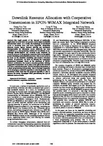
the line) to maximize the user throughput at cell boundary. In [5], the performance of a relay-assisted OFDMA network was evaluated for the specific setup of 3 RSs in a cell with and without intra-cell resource reuse. Numerical results showed that the relay-assisted system significantly outperforms the conventional cellular structure with respect to system capacity and coverage. Clearly, the performance investigation of relayassisted networks so far has been limited to very specific system setups: with fixed RS number and locations in a cell and/or fixed reuse patterns. In this work, the theoretical downlink performance of a general relay-assisted cellular network is investigated in a multi-cell environment. A genetic algorithm (GA) based approach is proposed for multi-cell optimization of the system parameters including RS positions, reuse pattern, path selection and resource allocation among different links to maximize the system spectral efficiency. Performance improvement offered by RSs and system design insights are discussed under different system setups. The rest of this paper is organized as follows. Section II describes the system models. In Sections III, the downlink optimizations are carried out under different criteria and system setups. Section IV gives the numerical results. Finally, the paper is concluded in Section V. II. S YSTEM M ODELS A. Relaying Technique In this paper, we consider that the RSs operate in the decode-and-forward mode, where the received signal is fully decoded and forwarded to destination, and use the same transmission technology as the BS at the same frequency band. All stations (BS, RS and MS) are equipped with one RF transceiver and an omni-directional antenna. In addition, MS can communicate with BS either through direct path or a 2hop path (via a RS) which constitutes the BS-RS link and the RS-MS link. B. Cell Architecture A general multi-cell network that consists of BSs, fixed RSs, and mobile stations (MSs) is investigated. Fig. 1 is such a network with cluster size (reuse factor) K equal to 3. Only the co-channel cells are considered where different number of RSs can be flexibly deployed in certain cells depending on the cell’s traffic load, the required QoE (quality of end-user experience) and others.
978-1-4244-2948-6/09/$25.00 ©2009 IEEE
This full text paper was peer reviewed at the direction of IEEE Communications Society subject matter experts for publication in the WCNC 2009 proceedings.
A
A
of BS and RSs. The spectral efficiency of a link is given by [10] µ ¶ pT · (Llin (d))−1 bps/Hz, (3) S(d) = log2 1 + N0 + I0
C B
B
A C
C
B
B
A
A1 C
X
B A
BS uses frequency band X Fixed RS
A
Multi-cell architecture with cluster size K = 3. Ω
R
R2
where pT is the transmit power spectral density (PSD), Llin (d) is the propagation loss in linear scale, and N0 and I0 are the PSD of AWGN and MAI, respectively. In addition, the spectral efficiency in (3) is independent of how much the bandwidth is allocated for the link, and the transmit power PT is equal to pT · W , where W is the link bandwidth. Let St be the targeted link spectral efficiency at the farthest cell edge, according to (3), the transmit PSD of BS is ¡ ¢ (R) Watts/Hz, (4) pB = 2St − 1 · (N0 + I0 ) · LNLOS lin
A
C
Fig. 1.
A
A2
R1
G G m − r1
G r1 G r2
BS
G m
G rN
2-hop Path
Frequency
Radio Resource for Direct-Path
Direct Path RN
MS
MS
Radio Resource for 2-hop Path (RS-MS Link)
Radio Resource for 2-hop Path (BS-RS Link)
Time
(a)
Fig. 2.
(b)
(a) A detailed layout of a cell, (b) radio resource allocation.
Fig. 2 (a) is a more detailed layout of a cell, where R is the cell radius, BS is located at the center of the cell, N RSs are deployed to improve the network performance, rj is the position vector of the j-th RS Rj , and m is the MS’s position vector. MSs are distributed uniformly over the cell region Ω. Fig. 2 (b) illustrates a practical radio resource allocation where orthogonal radio resources are allocated to direct path and 2hop path, respectively. The radio resource for 2-hop path is further divided into ones for the BS-RS link and the RS-MS link. With this allocation, RS does not need to transmit and receive at the same time (half-duplex relaying). C. Propagation Models The path loss is considered as the propagation impairment.1 The line-of-sight (LOS) and non-line-of-sight (NLOS) pathloss models for suburban macro-cell environment in [9] are adopted, which are given in (1) and (2), respectively. LLOS (d) = 23.8 log10 (d) + 41.9 dB,
(1)
LNLOS (d) = 40.2 log10 (d) + 27.7 dB,
(2)
where L(d) is the path loss (in dB), and d is the separation (in meters) between the transmitter and receiver. The LOS model is used for the BS-RS link because of the high position of the RS’s antenna, while the NLOS one is for the BS-MS link and the RS-MS link. Note that the NLOS model is also used for the calculation of multiple access interference (MAI). D. Power Setup A pre-specified theoretical spectral efficiency for users at the farthest cell edge is used to set up the transmitted power 1 The effects of shadow fading and small-scale fading can be easily included in the formulation if the formula of spectral efficiency in (3) is modified accordingly.
and the transmit PSD of Rj , j = 1, · · · , N is ¡ ¢ pRj = 2St − 1 · (N0 + I0 ) · LNLOS (R − krj k) Watts/Hz, lin (5) where krj k denotes the Euclidean norm of the vector rj , and I0 is a pre-specified PSD of MAI appearing at the cell farthest edge. This power setup guarantees the same spectral efficiency (under a fixed I0 ) at the cell edge no matter which path is selected for communication between BS and MS. Some other power setups apply equally well. E. Frequency Reuse over RS-MS Links In Fig. 2 (a), it is clear that the same radio resource can be reused in a cell over the RS-MS links to increase the spectral efficiency because of the spatial separation between RSs. To exploit this advantage, let RSs be divided into L groups, where L ≤ N , and each group shares the same radio resource. The reuse pattern then can be specified conveniently by the set . = {Rji } is the set of RSs in the G = {Gi }L i=1 , where Gi P i-th group. It is clear that L i=1 |Gi | = N , where |Gi | is the cardinality of the set Gi . III. D OWNLINK O PTIMIZATION
In the downlink, optimum RS positions, reuse pattern, path selection and bandwidth allocation of a 2-hop path are sought to maximize the cell spectral efficiency. Two QoE criteria are investigated: one is the fixed-bandwidth allocation (FBA), where a fixed bandwidth is allocated to MSs, and the other is the fixed-throughput allocation (FTA), where a fixed throughput (data rate) is supported no matter where the MS is located (uniform data rate coverage). In the following, the one-cell optimization will be presented first; the extension to joint multi-cell optimization is straightforward. A. Objective Function Let wB→M (m), wB→Rj (m), and wRj →M (m) denote the bandwidth per unit area (Hz/m2 ) allocated to the BS-MS link, the BS-RS link, and the RS-MS link, respectively. For a frequency reuse pattern G, the aggregate bandwidth (Hz) of the cell is obtained as Wcell = Wdirect + W2−hop ,
(6)
This full text paper was peer reviewed at the direction of IEEE Communications Society subject matter experts for publication in the WCNC 2009 proceedings.
where Wdirect =
Z
wB→M (m) dA,
(7)
m∈ΩB
and W2−hop =
N X
WB→Rj +
j=1
with
WB→Rj =
Z
wB→Rj (m) dA,
WR→M,l = max
Rj ∈Gl
WRj →M =
WR→M,l ,
(8)
l=1
m∈ΩRj
and
L X
Z
m∈ΩRj
© ª WRj →M ,
wRj →M (m) dA.
(9) (10)
(11)
Here, ΩB and ΩRj are the coverage areas of BS (direct-path) and Rj , respectively, and {ΩB , ΩR1 , · · · , ΩRN } is a partition of the cell region Ω. Furthermore, let
µ ¶ pB · (LNLOS (kmk))−1 lin , SB→M (m) = log2 1 + N0 + IB→M (m) µ ¶ −1 pB · (LLOS lin (krj k)) SB→Rj (rj ) = log2 1 + , N0 + IB→Rj (rj )
(12) (13)
and
µ ¶ (krj − mk))−1 pRj · (LNLOS lin SRj →M (m) = log2 1 + , N0 + IRj →M (m) (14) be the spectral efficiency of the BS-MS link, the BS-RS link, and the RS-MS link, respectively, where I(x) is the PSD of MAI appearing at the position x. Then, the theoretical throughputs per area (bps/m2 ) supported by the BS-RS link, the BS-RS link, and the RS-MS link are given respectively by tB→M (m) = wB→M (m) · SB→M (m), and
(15)
tB→Rj (m) = wB→Rj (m) · SB→Rj (rj ),
(16)
tRj →M (m) = wRj →M (m) · SRj →M (m).
(17)
Let tB→Rj →M (m) denote the effective throughput per unit area of the 2-hop path via Rj . It is clear that tB→Rj →M (m) = min{tB→Rj (m), tRj →M (m)}. It is proven that tB→Rj (m) = tRj →M (m) gives the highest spectral efficiency [8]. Using this, the aggregate throughput (bps) of the cell is obtained as N X T2hop,Rj , (18) Tcell = Tdirect + j=1
where
Tdirect =
Z
tB→M (m) dA,
(19)
tB→Rj →M (m) dA.
(20)
m∈ΩB
and T2−hop,Rj =
Z
m∈ΩRj
For FBA, both direct path and 2-hop path are allocated a fixed bandwidth wt , that is wt = wB→M (m) = wB→Rj (m) + wRj →M (m), while for FTA, wB→M (m), wB→Rj (m), and wRj →M (m) are allocated to achieve the targeted user throughput tt = tB→M (m) = tB→Rj →M (m) ∀ m. With these formulations, our objective is then to find the optimum RS . positions Υ = {r1 , r2 , · · · , rN } under a reuse pattern G such that the system spectral efficiency (bps/Hz) . Tcell , (21) Scell = Wcell is maximized. With the optimal cell spectral efficiency in (21), a further optimization can be carried out easily over the finite set of reuse patterns to find the ultimate highest spectral efficiency. Apparently, the system spectral efficiency depends on how the direct-path or 2-hop path is selected for communication between BS and MSs. Two path selection schemes are investigated: one is the received SINR-based, and the other is spectral efficiency-based. For the SINR-based path selection, the direct path is selected if SINRB→M (m) ≥ maxRj {SINRRj →M (m)}, otherwise, the 2-hop path via Ri is selected, where Ri = arg{maxRj {SINRRj →M (m)}}, SINRB→M (m) and SINRRj →M (m) are the received SINR at MS through direct-path and 2-hop path via Rj , respectively. For the spectral efficiency-based selection, for FBA, the direct t (m) (m) ≥ 2−hop , where t2−hop (m) = path is selected if tB→M wt wt maxRj {tB→Rj →M (m)}; otherwise the 2-hop path via Ri is selected, where Ri = arg{maxRj {tB→Rj →M (m)}}. For FTA, on the other hand, the direct path is se. tt tt lected if wB→M (m) ≥ w2−hop (m) , where w2−hop (m) = minRj {wB→Rj (m) + wRj →M (m)}; otherwise the 2-hop path via Ri is selected, where Ri = arg{minRj {wB→M (m) + wRj →M (m)}}. In the multi-cellular environment, the deployment of RSs in the co-channel cells can be jointly optimized to maximize the overall spectral efficiency. The optimization method developed in here can be applied equally well to the multi-cell case provided that Ω is considered as the overall cell region, N as the total number of RSs in the co-channel cells that involved in the joint optimization, and m and rj are as the position vectors to their own BS. B. Genetic Algorithm The spectral efficiency in (21) is a highly nonlinear function of the RS positions Υ, and, generally, an analytic solution is not available. In this section, a genetic algorithm (GA) is employed to solve the optimization problem in (21). GA is a stochastic search technique and has been successfully applied to a wide range of optimization problems that involve a large number of variables [11]- [12]. In our problem, GA-based approach is particularly useful when N is large and/or multicell optimization is required, where exhaustive search is quite inefficient. Fig. 3 shows the block diagram of GA operations. It is started with generating random population of a set of
This full text paper was peer reviewed at the direction of IEEE Communications Society subject matter experts for publication in the WCNC 2009 proceedings.
Generation of initial population
to be one of the parents with probability given in (22), Scell (Υk ) , P (Υk ) = P Υi Scell (Υi )
Fitness evaluation
Y
Optimal or good solution found?
Done N
Mate selection
•
Crossover Mutation
Fig. 3.
A block diagram of GA.
chromosomes which are possible solutions to our problem in (21). Each chromosome will be evaluated against the objective function (21), and then a selection criterion is applied based on survival of the fittest, which means chromosomes with less fitness will be eliminated while chromosomes with better fitness survive. The genetic evolution includes the operations of crossover and mutation. The crossover is carried out over the selected chromosome mates to reproduce new offspring who inherits partial genes from parents. Mutation is performed for a few offspring where some genes may be altered, which forces the algorithm to explore other areas of the solution space. The evolution process repeats from one generation to another until certain condition (for example, number of iterations or improvement of the best solution) is satisfied. The evaluation of fitness of the population is easy to accomplish in parallel which allows the algorithm to explore several promising areas of the solution space at the same time with less likely getting stuck in a local extreme. The parameter of GA operations used in this paper is detailed as follows. •
•
•
•
Chromosome Representation: The Cartesian coordinate of a RS (rj ) is encoded as a gene, and the set of N RS positions Υ = [r1 , r2 , · · · , rN ] denotes a chromosome. In our formulation, the cell region is discretized into grids with rj located at a vertex of the grids. Initial Population: In the beginning, Npop chromosomes are randomly generated and will involve in the evolution. Each randomly generated coordinate is rounded into the nearest grid. Fitness Evaluation: Each chromosome Υ is evaluated by ( 21). The best Nsur fitter chromosomes, where Nsur = β · Npop with β is the selection rate to survival, survive after evaluation and will involve in the next evolution, while the rest are discarded to make room for the new offspring. Mate Selection: Two mates (chromosomes) are selected from the mating pool of Nsur chromosomes to produce two new offspring. The most commonly used mate selection scheme in GA applications: Roulette wheel selection [11] is applied, where the survival chromosome is chosen
•
(22)
where Scell (Υk ) is the fitness value for the particular chromosome Υk . (22) shows that the fitter chromosome (to have good genes to survive) will have higher chances to be selected to create offspring. Crossover: The uniform crossover is adopted in this work to produce two offspring from two selected mates, where each gene in offspring is randomly decided whether or not to interchange information between the two mates [11], [12]. In addition, in a real-valued encoding scheme a small zero-mean random perturbation is suggested to add to each each gene of the offspring in order to prevent the evolutions being dominated by few genes [12]. In our method, the Gaussian variable with variance equal to a grid length, which is specified in section IV, is used as the perturbation. Mutation: A mutation probability Pmut is set to determine whether a gene is mutated or not. Once a mutation is performed, the coordinate of the corresponding RS will be regenerated. The purpose of mutation is to avoid the GA overly fast converging into a local optimum.
IV. S YSTEM P ERFORMANCE In our experiments, the cell radius is set as 1400 meters, and the cell region is divided into grids with each side equal to 20 meters, where all stations (BS, RSs, and MS) are located at the grid vertices. Four cases of system setup will be considered, including FBA with spectral efficiency-based path selection (FBA-SE), FBA with SINR-based path selection (FBA-SINR), FTA with SE-based path selection (FTA-SE) and FTA with SINR-based path selection (FTA-SINR). St = 0.5 bps/Hz, Npop = 200, β = 0.5 and Pmut = 0.05 are adopted in GA. Note that the number of generations depends on the number of RSs involved; more generations are needed for a larger number of RSs. For convenience, all results are obtained with wt = 1 Hz/m2 for FBA, and tt = 1 bps/m2 for FTA. A. Single-Cell Fig. 4 shows the idea how RSs are optimally placed and how they can do to improve the user throughput (spectral efficiency) for FBA-SE. No frequency reuse is considered. Fig. 4 (a) shows the case of no RS (N = 0), where 23.37 bps throughput is achieved at the locations close to BS and 0.5 bps at the farthest cell edge (as planned at the power setup of BS). Fig. 4 (b) shows the case of two RSs, where they are placed on the lines connecting the cell center and two vertices of the hexagonal cell, at distance of 680 meters from BS. As can be seen, user throughput is improved significantly at the close proximity of RSs. Note that the optimal placement of RSs is not unique in this case; as long as RSs are placed on the lines connecting the cell center and any two of vertices at the same distance from BS, the system performs equally well. Fig. 4 (c) illustrates the case of six RSs. Again, RSs are placed on the lines connecting the cell center and vertices, and
This full text paper was peer reviewed at the direction of IEEE Communications Society subject matter experts for publication in the WCNC 2009 proceedings. TABLE I I MPORTANT PARAMETERS FOR FOUR SYSTEM SETUPS . N
0
2
4
6
8
10
12
14
(a) FBA-SE
ΩB :ΩR (%) WB→M : WB→R :WR→M (%) Scell (bps/Hz)
100:0 100:0:0 2.7382
77:23 77:5:18 2.9698
54:46 54:9:37 3.2014
31:69 31:14:55 3.4329
23:77 23:17:60 3.6398
22:78 22:18:60 3.7986
21:79 21:19:60 3.9142
22:78 22:20:58 4.0024
ΩB :ΩR (%) (b) FBA-SINR
WB→M : WB→R :WR→M (%)
100:0 100:0:0 2.7382
75:25 75:5:20 2.9605
52:48 52:10:38 3.1821
27:73 27:15:58 3.4043
19:81 19:18:63 3.6148
18:82 18:19:63 3.7773
18:82 18:20:62 3.8960
20:80 20:20:60 3.9848
100:0 100:0:0 0.6423 1.5570
82:18 84:2:14 0.5906 1.6932
65:35 66:5:29 0.5390 1.8552
47:53 43:8:49 0.4874 2.0516
36:64 30:11:59 0.4500 2.2221
31:69 22:13:65 0.4135 2.4181
31:69 18:14:68 0.3826 2.6134
32:68 20:15:65 0.3647 2.7421
100:0 100:0:0 0.6423 1.5570
82:18 83:3:14 0.5913 1.6912
63:37 63:5:32 0.5403 1.8508
44:56 39:9:52 0.4895 2.0429
34:66 27:11:62 0.4518 2.2134
28:72 17:14:69 0.4152 2.4087
28:72 15:15:70 0.3835 2.6073
29:71 17:15:68 0.3662 2.7311
Scell (bps/Hz) ΩB :ΩR (%)
(c) FTA-SE
WB→M : WB→R :WR→M
(%)
W (Hz) Scell (bps/Hz) ΩB :ΩR (%)
(d) FTA-SINR
WB→M : WB→R :WR→M (%)
W (Hz) Scell (bps/Hz)
1 0.9 0.8 0.7
0.5
r
P (X≤x)
0.6
N=0 N=2 N=4 N=6 N=8 N=10 N=12 N=14
0.4 0.3
(a) N=0
(b) N=2
0.2 0.1 0
0
Fig. 5.
(c) N=6 Fig. 4.
(d) N=14
Optimal RS positions and throughput distribution for FBA-SE.
all of them locate on the ring with distance of 680 meters from BS. As the number of RS increases, however, the optimal RS locations can split into more than one ring so as to maximize the system spectral efficiency, as one might expect. Fig. 4 (d) is such an example with fourteen RSs. Table I (a) summarizes the important system parameters including service areas of BS and RSs, bandwidth allocation ratio for BS-MS link, BS-RS link and RS-MS link, and the system spectral efficiency. As can be seen, the system spectral efficiency is improved significantly with the deployment of RSs; around 4.23% for each addition of RS when N ≤ 6. The improvement becomes smaller, however, as the number of RS is larger than 6, where RSs begin to compete with each other for serving MS rather than to compete with BS. Fig. 5 shows the cumulative distribution function (CDF) of user throughput for different N . It is shown that the percentage of user with low throughput decreases as N increases. In other words, the achievable data-rate is distributed more uniformly over the cell. Further, we see that the improvement becomes saturated when N ≥ 12. Finally, the CDF approaches to 1 as the throughput is increased to the maximum throughput of 23.37 bps, where all lines merge together at that region. As to FBA-SINR, the optimal RSs are placed in a way
1
2
3 4 5 User throughput (bps), x
6
7
8
CDF of user throughput for FBA-SE.
similar to FBA-SE except that generally the RSs are a bit far from BS than that of FBA-SE. Table I (b) is the summary of important system parameters. After system optimization with GA, somewhat surprising that FBA-SINR performs very closely to that of FBA-SE with respect to the system spectral efficiency. Although the criteria are different, GA always searches the optimum RS locations to maximize the system spectral efficiency. Note that SINR-based path selection is much simpler to implement than the SE-based one. Table I (c) and (d) show the important system parameters of FTA-SE and FTA-SINR, respectively. As can be seen, with RSs, it is more bandwidth efficient to achieve uniform data rate coverage. The average bandwidth consumption is reduced as the number of RSs increases. On the other hand, there is little difference between SE-baed path selection and SINR-based one after system optimization. From Table I, it is also seen that the system spectral efficiency of FBA is much smaller than that of FTA because a lot more bandwidth is required to maintain a fixed data rate for MSs who are in bad channel conditions. To further utilize the radio resource, frequency reuse over the RS-MS link is explored. The case of six RSs is taken as an example with the following reuse patterns, G = {G1 }, G = {G1 , G2 }, G = {G1 , G2 , G3 } and G = {G1 , G2 , G3 , G4 , G5 , G6 }, where each reuse group has equal number of RSs. Fig. 6 depicts the throughput distribution of FBA-SE. Circles with same letter indicate the service area of RSs in the same reuse groups. Again, RSs are placed on the line connecting cell center to six vertices of the cell, with RSs in the same reuse group being pulled away as far apart
This full text paper was peer reviewed at the direction of IEEE Communications Society subject matter experts for publication in the WCNC 2009 proceedings. 1500
1500 22
18
Y (m)
2
G
12
12
10
G
G3
5
G3
2
−500
G −1000
8
G1
6 4
−500
0 X (m)
4
500
1000
(a) G={G1 , G2 , G3 , G4 , G5 , G6 }
−1000
−500
0 X (m)
500
1000
1500
22
20 1000
1
500
G
2
18
12
0
10
G
G1
1
−500
8
16
G
G
1
14 Y (m)
G
2
Y (m)
G
18 16
500
1
14 12
0
10
G
−500
G
1
8
1
6
G
6
2
4
−1000
G
4
1
−1000
2 −1000
−500
0 X (m)
500
1000
2 −1500 −1500
1500
−1000
(c) G = {G1 , G2 }
−500
0 X (m)
500
1000
1500
(d) G = {G1 }
Fig. 6. Throughput distribution (bps/m2 ) of different frequency-reuse patterns for FBA-SE (N=6).
System spectral efficiency (bps/Hz)
6
5
FBA−SE FBA−SINR FTA−SE FTA−SINR
4
3
2
1
0 {G1,G2,G3,G4,G5,G6}
Fig. 7.
{G1,G2,G3}
0.8
G
3
0.6
G
G
4
4
0.4
0.4
−1000
−1500 −1500
−1000
−500
0 X (m)
500
1000
1500
0.2 −1500 −1500
−1000
−500
0 X (m)
500
1000
1500
(b) Cell A2
Fig. 8. RSs positions of jointly designed cells and distribution of bandwidth consumption (Hz/m2 ) for FTA-SE.
20
1000 1
1 G5
−500 0.6
(a) Cell A1
1500
22
1.2
0
0.2
(b) G = {G1 , G2 , G3 }
1500
2
4 2
−1500 −1500
G
6
0.8
G3
5
−500
−1000
−1000
1500
G
G
6
2 −1000
1
0
10
G
8
G
1.2
14
0
1.4 500
G2
G
6
G2
3
14
0
−500
1
1.4 500
Y (m)
G
1.6 G
1
16
500
1.8 1000
1.6
G
1
6
−1500 −1500
1000
18
G
16
G
Y (m)
500
−1500 −1500
1.8
20 1000
G1
1500
22
20 1000
Y (m)
1500
{G1,G2}
{G1}
Scell of different frequency-reuse patterns (N=6).
as possible. In the fully reuse case, as is shown in Fig. 6(d), severe interference leads to a shrinking of the service area of RSs. With respect to system spectral efficiency, the reuse cases always outperform the no reuse cases, as is shown in Fig. 7, where the reuse pattern G = {G1 , G2 } gives the highest spectral efficiency. Also, it is very interesting to see that SINR-based path selection has a higher spectral efficiency than the SE-based path selection for both FBA and FTA in the frequency-reuse cases. This can be attributed to that RSs have larger service area in the SINR-based path selection and that leads to a larger bandwidth saving in the frequency-reuse case. Note that in this example, the reuse pattern G = {G1 , G2 , G3 } gives the largest service area of RS while G = {G1 , G2 } gives the highest system spectral efficiency; there is a tradeoff between MAI and frequency reuse. B. Multi-Cell In this part, Fig. 1 shows an example used to illustrate how the joint optimization is done over multiple cells, where a total of 12 RSs are jointly deployed in the cells A1 and A2 with 6 RSs per cell. The reuse factor K equals to 3, and the first tier co-channel interference is taken into account for both cells in the optimization. No intra-cell frequency-reuse among RSs is considered. Fig. 8 shows the optimal placement of RSs
and the distribution of bandwidth consumption for FTA-SE.As expected, cell A1 and A2 have almost the same layout, and RSs in the same group are placed as far apart as possible in order to reduce the co-channel interference. V. C ONCLUSIONS In this work, the downlink performance of relay-assisted cellular networks is investigated with optimized system parameters. A genetic-algorithm based approach is proposed for joint multi-cell optimization of system parameters including RS positions, path selection, reuse pattern and resource allocation to maximize system spectral efficiency. Four different system setups are investigated including FBA-SE, FBA-SINR, FTASE, and FTA-SINR. Numerical results show that (i) RSs provide significant improvement with respect to system spectral efficiency and user throughput over the traditional cellular systems, (ii) uniformity of user data rate comes at the expense of a large loss in system spectral efficiency when FTA is employed, and (iii) somewhat surprising, the low-complexity SINR-based path selection performs nearly as good as the SEbased one for the no reuse case while slightly better in the frequency-reuse case. R EFERENCES [1] ITU-R M.1645, “Framework and overall objectives of the future development of IMT-2000 and systems beyond IMT-2000,” 2003. [2] R. Pabst, et al., “Relay-based deployment concepts for wireless and mobile broadband radio,” IEEE Commun. Mag., pp. 80-89, September 2004. [3] H. Hu, H. Yanikomeroglu, D. D. Falconer and S. Periyalwar, ”Range extension without capacity penalty in cellular networks with digital fixed relays”, in Proc. IEEE Global Telecommunications Conference, pp. 3053-3057, November, 2004. [4] P. Li, et al., “Spectrum partitioning and relay positioning for cellular system enhanced with two-hop fixed relay nodes,” IEICE Trans. Commun., vol, E90-B, pp. 3181-3188, Novermber 2007. [5] R. Pabst, D.C. Schultz and B.H. Walke, “ Performance evalaution of a relay-based 4G network deployment with combined SDMA/OFDMA and resource partitioning,” in Proc. IEEE VTC 2008-Spring, pp. 20012005, May 2008. [6] D. Soldani and S. Dixit, “Wireless relays for broadband access,” IEEE Commun. Mag., pp. 58-66, March 2008. [7] IEEE 802.16j-06/026r4, “Part 16: Air interface for fixed and mobile broadband wireless access systems: multihop relay specification,” June, 2007. [8] W. H. Sheen and S. J. Lin, NSC Technical Report, NSC-96-2221-E009060 [9] IST-2003-507581 WINNER D5.4, https://www.ist-winner.org/ [10] T. Cover and J. Thomas, Elements of Infomation Theory. John Wiley and Sons, 1991. [11] R. L. Haupt and S. E. Haupt, Practical Genetic Algorithms. John Wiley and Sons, 2004. [12] E. K. P. Chong and S. H. Zak, An introduction to optimization. John Wiley and Sons, 2001.