This article has been accepted for inclusion in a future issue of this journal. Content is final as presented, with the exception of pagination. IEEE TRANSACTIONS ON ELECTROMAGNETIC COMPATIBILITY
1
Machine Learning Based Source Reconstruction for RF Desense Qiaolei Huang, Student Member, IEEE, and Jun Fan, Fellow, IEEE
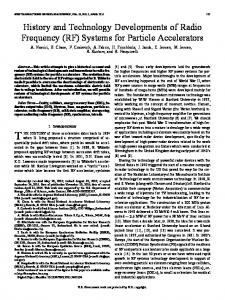
Abstract—In radio frequency interference study, equivalent dipole moments are widely used to reconstruct real radiation noise sources. Previous reconstruction methods, such as least square method (LSQ) and optimization method are affected by parameter selections, such as number and locations of dipole moments and choices of initial values. In this paper, a new machine learning based source reconstruction method is developed to extract the equivalent dipole moments more accurately and reliably. Based on the near-field patterns, the proposed method can determine the minimal number of dipole moments and their corresponding locations. Furthermore, the magnitude and phase for each dipole moment can be extracted. The proposed method can extract the dominant dipole moments for the unknown noise sources one by one. The proposed method is applied to a few theoretical examples first. The measurement validation using a test board and a practical cellphone are also given. Compared to the conventional LSQ method, the proposed machine learning based method is believed to have a better accuracy. Also, it is more reliable in handling noise in practical applications. Index Terms—Cellphone, desense, dipole moment, electromagnetic compatibility (EMC), histogram of oriented gradients (HOG), machine learning, radio frequency interference (RFI), support vector machine (SVM). Fig. 1.
RF antennas and noise sources inside a cellphone.
I. INTRODUCTION ODERN connected electronic devices typically have multiple radio frequency (RF) antennas. For example, today’s cellphones have multiple antennas to offer connectivity covering Wi-Fi, Bluetooth, global positioning system, global system for mobile communication, and several long-term evolution bands. Together, all of these antennas cover a relatively wide frequency range. Other trends for electronics include shrinking device sizes and increasing clock speeds and data rates. Many components within a cellphone, such as the display module, camera module, and CPU chips, can radiate and potentially couple to one of the many RF antennas [1]. These unintentional noise sources might radiate in a broad frequency band, so it is highly possible that the noise spectrum falls into the frequency range of the multiple RF antennas. Also, RF antennas often have high sensitivities to ensure high speed data communications. Even weak radiation from an unintentional noise source
M
Manuscript received December 29, 2017; accepted January 14, 2018. This work was supported in part by the National Science Foundation under Grant IIP-1440110. (Corresponding author: Jun Fan.) The authors are with the EMC Laboratory, Missouri University of Science and Technology, Rolla, MO 65401 USA (e-mail:
[email protected];
[email protected]). Color versions of one or more of the figures in this paper are available online at http://ieeexplore.ieee.org. Digital Object Identifier 10.1109/TEMC.2018.2797132
can be picked up by the RF antennas. This unintentional coupling to the RF antennas degrades the sensitivity of the antennas. This problem is known as RF desense. An illustration of this problem is shown in Fig. 1. To understand the desense issue, the first step is to identify the noise sources and obtain accurate models of the noise sources. The most straightforward method is to model the whole problem directly using full wave simulation. However, this direct simulation often takes a long time. If a certain change is made during debugging, another round of full wave simulation is needed. Further, noise sources like integrated circuits (ICs) are typically quite difficult to model due to their complexity. Design engineers do not always have the access the exact geometrical details of an IC due to intellectual property protection from IC companies. Thus, the direct simulation is often not the best choice. Recently, many efforts have been focused on equivalent dipole moment modeling for radiation sources [2]–[4]. An array of electric and magnetic dipole moments is used to replace the radiation source, based on near-field scanning measurements. The extracted dipole moments are relatively easy to import into full wave simulation tools [4]. If designers have both the equivalent dipole moment source model and the three-dimensional model of victim antenna, the rest of the coupling problem can be done using full wave simulation. So the key is to obtain an accurate
0018-9375 © 2018 IEEE. Personal use is permitted, but republication/redistribution requires IEEE permission. See http://www.ieee.org/publications standards/publications/rights/index.html for more information.
This article has been accepted for inclusion in a future issue of this journal. Content is final as presented, with the exception of pagination. 2
IEEE TRANSACTIONS ON ELECTROMAGNETIC COMPATIBILITY
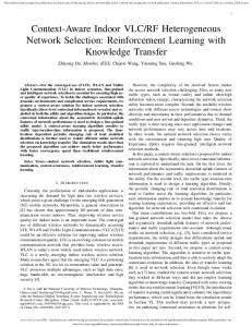
Fig. 2. Similarities between a typical computer vision problem and the source reconstruction problem. (a) A table and a chair can be identified in the picture. (b) Dipole moment sources need to be extracted from the near-field plot of a cellphone. Fig. 3.
equivalent model for the real noise source. Previously, a uniform array of electric and magnetic dipole moments is predefined to replace the noise source. The least square method (LSQ) is then used to solve the magnitude and phase of each dipole moment. However, this method is prone to measurement noise of the near-field data which is inevitable in near-field scanning experiments. In particular, when the number of dipole moments is large, the solution from the LSQ method may be nonphysical. Although a nonphysical solution can match the field well at the scanning plane, it fails to predict the fields well at other locations [4]. In [5] and [6], optimization algorithms are used. The performance of the optimization algorithms depends heavily on the initial value. The optimization algorithms will fail if a bad initial value is chosen. A more reliable method is needed to reconstruct equivalent dipole moments accurately and also with physical meanings. Although the described problem is encompassed within the field of electromagnetics, it is beneficial to look at the problem from another perspective. The objective of the problem is to extract information (equivalent dipole moment sources) from near-field plots. This is very similar to a typical computer vision problem, where computers attempt to extract information from images or videos. For example, in Fig. 2(a), the image contains a table and a chair. After adequate training, machine learning algorithms are able to identify both the chair and the table. In a similar fashion, algorithms can be trained to identify the dominant dipole moments from near-field plots. A typical nearfield pattern for a cellphone is shown in Fig. 2(b). In this paper, a machine learning algorithm is developed by using a training set consisting of the field patterns for the six basic dipole moments. After the training, the algorithm is capable of extracting the primary dipole moment from more complicated field patterns. Once the type of dipole moment is identified, the location of the dipole moment is further determined using autocorrelation. The LSQ is used to extract the magnitude and phase for this dominant dipole moment. After the first and most dominant dipole moment is extracted, a new field pattern is generated by subtracting the field pattern of the first dipole moment from the original field pattern. The same process is repeated on the newly obtained field pattern. The iteration stops when the difference between the field pattern from the extracted dipole moments and the field pattern from the measurement meets a certain criterion or a maximum iteration number reaches. In this way, the most dominant dipole moments for the complex noise source
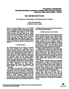
Six types of basic dipole moment sources.
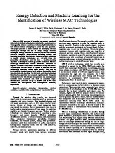
can be extracted one by one. The proposed method is applied to a few theoretical examples first. The measurement validations using a test board and a practical cellphone are also given. II. MACHINE LEARNING BASED SOURCE RECONSTRUCTION Dipole moments are the most basic radiation sources. The electric dipole moment consists of an infinitely small electric current segment, denoted as a P dipole moment. By duality, a magnetic dipole moment is an infinitely small magnetic current segment, denoted as an M dipole moment. An infinitely small magnetic current segment is actually an infinitely small electric current loop. For a magnetic dipole moment, the direction is defined as the perpendicular direction to the plane of the electric current loop. For example, an Mx dipole moment denotes the magnetic current going toward the x-direction, or the electric current loop in the yz plane. Based on orientations, there are six types of basic dipole moments, as shown in Fig. 3. For the basic dipole moments, the near and far fields can be calculated from the analytical formulas given in [4]. Thus, the field patterns above the noise source can be analytically calculated. The goal is to obtain a field pattern database from the six basic dipole moments. The machine learning algorithm is trained by these field patterns. In order to mimic the noise in real measurements, different amounts of small random noise are added to the ideal dipole moments. For example, the Hx patterns for the magnetic dipole My are shown in Fig. 4. Clearly, every field pattern is different because of the added random noise. However, the overall shape of the pattern is the same butterfly shape. The butterfly shape is the key feature in identifying the My dipole moment. The whole training set is formed by 600 field patterns from the six types of basic dipole moments. Different types of dipole moments have different field patterns. Local features of the field pattern are used to classify the dipole moment type. In computer vision, local features are compact vector representations of a local neighborhood inside a picture and are the building blocks of many computer vision algorithms. In this study, a histogram of oriented gradients (HOG) is used to extract the local features from different field patterns. According to Dalal and Triggs [7], HOG provides an excellent performance for human detection. HOG is therefore expected to be sufficient enough to extract the local features of field patterns in this work. Fig. 5 shows a field pattern and its
This article has been accepted for inclusion in a future issue of this journal. Content is final as presented, with the exception of pagination. HUANG AND FAN: MACHINE LEARNING BASED SOURCE RECONSTRUCTION FOR RF DESENSE
Fig. 4.
3
H x field patterns for M y dipole moment with random noise added.
Fig. 7.
Fig. 5.
(a) Field pattern from the training database. (b) HOG features.
Fig. 6.
Workflow of machine learning algorithm.
corresponding HOG features. In machine learning, support vector machine (SVM) is a type of supervised learning used for classification analysis. In this work, given a set of training field patterns, each field pattern is marked as belonging to one dipole moment category. The SVM algorithm is trained by those field patterns and its corresponding category. After the training, the algorithm will be able to identify the main dipole moment for complicated field patterns. The workflow of the machine learning algorithm is shown in Fig. 6. After the validated machine learning algorithm is obtained, it is utilized to extract equivalent dipole moments, one by one, from an unknown field pattern. The workflow is shown in
Workflow of machine learning based dipole moment extraction.
Fig. 7. First, the unknown field pattern is represented with HOG features. Then, the validated machine learning algorithm will determine the dominant type of dipole moment in this unknown field pattern. Once the type of the dominant dipole moment is identified, the autocorrelation between the unknown field pattern and the field pattern of the dominant dipole moment is used to identify the location of the dipole moment. After the type and location of the most dominant dipole moment is determined, LSQ is used to find the magnitude and phase. Because there is only one dipole in this LSQ method, the issue of overfitting in the conventional LSQ method is intelligently solved here. In this way, the first and most dominant dipole moment for the unknown noise source is successfully obtained. The error between the unknown field and the field of the dominant dipole moment is further calculated. If the error is smaller than the defined criteria, the process will end. It means that the unknown noise source contains only one dominant dipole moment. However, if the error is larger than a certain criteria, it means that the dominant dipole moment cannot sufficiently represent the unknown noise source. In this case, a new field pattern is obtained by subtracting the field of the dipole moment from the original field pattern. The new field pattern goes through the whole process again to obtain the second dominant dipole moment source. In this way, the most dominant dipole moments can be extracted one by one. III. VALIDATIONS Two theoretical examples are discussed below to validate the proposed method. The first theoretical example is shown in Fig. 8. For an unknown noise source, the near-field patterns of Hx and Hy are provided. Using the traditional method of mapping hot spots, there are at least 7–8 radiation sources. In later discussion, this claim is shown to be incorrect. In comparison, the proposed machine learning method can provide the correct source reconstruction. It can also generate the minimum
This article has been accepted for inclusion in a future issue of this journal. Content is final as presented, with the exception of pagination. 4
Fig. 8.
IEEE TRANSACTIONS ON ELECTROMAGNETIC COMPATIBILITY
Field patterns of H x and H y for an unknown noise source.
Fig. 10. H x and H y patterns from the extracted dipole moments. (a) Magnitude of H x and H y from the most dominant dipole moment M x . (b) Magnitude of H x and H y from the second most dominant dipole moment M y .
Fig. 9. Workflow of the machine learning based source reconstruction on the unknown source in Fig. 8.
number of dipole moments for this unknown noise source. The detailed dipole moment extracting procedure is shown in Fig. 9. For the given input field pattern, the algorithm will first find the maximum field position and pick out the nearby field based on a certain threshold. Using this process, the first pattern is cut out from the original field pattern. The first pattern is sent to the pretrained machine learning algorithm. The machine learning algorithm determines the type of the dipole moment. After the type of dipole moment is determined, the location of the dipole moment is further determined using autocorrelation. The LSQ method is used to solve the magnitude and phase of the first dipole moment. In this way, the first and most dominant dipole moment is extracted. The field for the extracted dipole moment is then subtracted from the original field pattern, resulting in a new field pattern. The dipole extraction and field subtraction procedure is repeated on this new field pattern until a certain error criteria is reached. The original field pattern can be well represented by the extracted dipole moments. The tangential H field from the most dominant dipole moment Mx and the second most dominant dipole moment My is shown in Fig. 10(a) and (b). For the unknown noise source in Fig. 8, it turns out that there are two dominant dipole moments inside the source. The most dominant dipole is an Mx dipole. The second dominant dipole is an My dipole. Using the proposed source reconstruction method, the two dipole moments can be extracted, along with the corresponding magnitude and phase. Because the two dipole moment sources in Fig. 8 are located sufficiently far away, the two field patterns are relatively recognizable. A second theoretical example with a more
Fig. 11.
Field patterns of H x and H y for another unknown noise source.
Fig. 12. Workflow of the machine learning based source reconstruction on the unknown source in Fig. 11.
complex pattern is also provided to demonstrate the robustness of the proposed method. The field pattern for an unknown noise source is shown in Fig. 11. The patterns in Fig. 11 cannot be easily recognized. The machine learning based source reconstruction method can still work correctly. The workflow is shown in Fig. 12. For the unknown noise source in Fig. 11, it turns out that there are two dominant dipole moments inside the source. The most dominant dipole is an My dipole moment, which is
This article has been accepted for inclusion in a future issue of this journal. Content is final as presented, with the exception of pagination. HUANG AND FAN: MACHINE LEARNING BASED SOURCE RECONSTRUCTION FOR RF DESENSE
Fig. 15. method.
Fig. 13. H x and H y patterns from the extracted dipole moments. (a) Magnitude of H x and H y from the most dominant dipole moment M y . (b) Magnitude of H x and H y from the second most dominant dipole moment M x .
Fig. 14.
RFI from the unknown noise source to the patch antenna.
extracted out first by the algorithm. The second most dominant dipole is an Mx dipole moment. These two dipole moments are located at the same place. Compared to the field pattern of Fig. 8, this is more complex, because the near field is affected by the magnitude and phase of these two dipole moments. This is also the reason that the field patterns are not easily recognized. Using the proposed source reconstruction method, the two dipoles can be successfully extracted with the correct magnitude and phase. Fig. 13 shows the field patterns from these two dipole moments. It is worthwhile to mention that phase information of the near field is needed here if two dipole moments are close. Without phase information of the near field, the two closely placed dipole moments cannot be correctly separately. IV. RF DESENSE APPLICATIONS A. Numeric Simulation Example A simulation example of a radio frequency interference (RFI) problem is discussed in this section. In Fig. 14, the RFI between
5
Total of 1200 dipole moments are used in the conventional LSQ
the unknown noise sources to the Wi-Fi patch antenna is studied. The patch is 37.2 mm × 28 mm. The unknown noise source is placed at the right side of the printed circuit board (PCB). The unknown noise source generates the field pattern in Fig. 11. The field is taken 3 mm above the noise source. Based on the work in [4] and [8], the forward problem and reverse problem are needed to predict coupling from noise source to antenna. In the forward problem, the real noise source is turned ON and the victim antenna is turned OFF. In the reverse problem, the antenna is excited and the noise source is turned OFF. After the previous steps of the machine learning based source reconstruction, the forward problem is solved and equivalent dipole moments for the noise source are extracted. In the reverse problem, transfer functions are obtained when the victim antenna radiates. Using the equivalent dipole moments and the transfer functions, the coupled voltage from the noise to the victim antenna can be analytically calculated. In order to show the correctness of the proposed method, the direct simulation is also performed for comparison. Similarly, the conventional LSQ method is further used to obtain the equivalent dipole moments for the noise source. An array of dipole moments is used. The dipole moments are uniformly placed at the points of 20 mm × 20 mm grid. There are three types of dipole moments (Pz , Mx , My ) at each point. A total of 1200 dipole moments are used here, as shown in Fig. 15. LSQ is utilized to solve the magnitude and phase of the 1200 dipole moments. Combining the 1200 dipole moments and the transfer functions from the reverse problem, the coupled voltage using this conventional LSQ method can also be obtained. The predicted RFI results from the machine learning based method and the conventional LSQ method are compared with direct simulation in Fig. 16. In this ideal case, the proposed machine learning based method agrees with the direct simulation very well. The accuracy of the conventional LSQ method is worse than the machine learning based method. In order to mimic the noise effect in real world measurements, random noise is added to the field plots in Fig. 11, the same procedures are repeated to compare the RFI from the machine learning based method, the conventional LSQ method, and direct simulations. The result comparisons are shown in Fig. 17. The proposed machine learning method still works fine. The conventional LSQ method fails, as it is sensitive to noise especially when the number of unknowns is large.
This article has been accepted for inclusion in a future issue of this journal. Content is final as presented, with the exception of pagination. 6
Fig. 16. RFI comparisons from the proposed machine learning method, conventional LSQ method, and direct simulation.
IEEE TRANSACTIONS ON ELECTROMAGNETIC COMPATIBILITY
Fig. 18.
RFI from the noise IC to the patch antenna.
Fig. 19.
Measured H x and H y magnitude above the noise IC.
Fig. 17. After adding noise to the field patterns, RFI comparisons from the proposed machine learning method, conventional LSQ method, and direct simulation.
B. Measurement Validation Using a Test Board In this section, the measurement validation of the proposed method is performed using a simple test board. The RFI from a test IC to the above path antenna is studied. The test IC is a clock butter IC. The length and width of the IC is about 5 mm × 5 mm. Similarly as discussed in the previous section, the forward problem and the reverse problem are needed to predict coupling from the noise source to the victim antenna. The measurement setup for the forward problem and the reverse problem is shown in Fig. 18. The measured Hx and Hy magnitude are shown in Fig. 19. According to the proposed machine learning algorithm, the dominant dipole moment is identified as an Mx dipole moment. The contribution of the other types of dipole moments is negligible. It is clearly observed that the proposed machine learning based method can utilize the field patterns to find the correct location and minimal number of the dipole moments. In comparison, conventional LSQ method just simply uses a large array of dipole moments regardless of the field patterns [9]. The array of dipole moments is usually placed to cover the hot spot region. There is a high possibility that the location and number of the dipole moment array are incorrectly
Fig. 20. RFI comparison of the proposed machine learning method, conventional LSQ method, and real measurement.
chosen. Nevertheless, a total number of 1200 dipole moments are used to reconstruct the noise IC in the conventional LSQ method. The predicted RFI results from the machine learning based method and the conventional LSQ method are compared with direct simulation in Fig. 20. In this measurement example, the results from the proposed machine learning based method agree with the direct simulation very well, with the error less than 3 dB. The conventional LSQ method is much worse than the machine learning based method. The results also show that assigning more dipole moments for a noise source reconstruction is not necessarily a good choice. Noise effect and the overfitting issue are the main reasons why a large array of dipole moments can provide incorrect results. On
This article has been accepted for inclusion in a future issue of this journal. Content is final as presented, with the exception of pagination. HUANG AND FAN: MACHINE LEARNING BASED SOURCE RECONSTRUCTION FOR RF DESENSE
Fig. 21.
Physics of the M x dipole moment. Fig. 23.
Fig. 22.
7
Workflow of the dipole moment extraction.
Magnitude of H x and H y field patterns above LCD of a cellphone.
contrast, in the machine learning based method, the noise effect is not that significant. First, when training the SVM, different noise levels are added to the field patterns, as shown previously in Fig. 4. The algorithm itself is well suitable to handle noise. Second, it is worthwhile to mention that the machine learning algorithm used in this work is SVM. Although SVM is powerful and simple to use, it is believed that recent deep learning algorithms [10], such as convolutional neural network [11] can provide an even better accuracy. The side effect of measurement noise can be well handled here. Another advantage of this machine learning based method is that the dominant dipole moments are provided. In this test IC, the dominant dipole moment is a single magnetic dipole moment Mx . The physics of how an Mx dipole moment is formed in this test IC is analyzed in Fig. 21. From the left side, the highspeed signal is routed inside the stripline structure. Because of the shielding effect of the solid ground, the radiation from the stripline part is negligible. The signal trace jumps from the inner part of the board to the top side in order to connect to the IC pin. The return current for the high-speed signal is through the central ground pad. In this way, a current loop is formed in the yz plane. By definition, a current loop in the yz plane is an Mx dipole moment. Knowledge of the dominant dipole moment can help engineers to propose effective methods to solve RF desense issues. For instance, in this test board, reducing the magnitude of the Mx dipole moment can lead to a decrease of the coupling to the victim antenna. Reducing the current on the loop or reducing the loop size can both help achieve a smaller coupled noise on the victim antenna. C. Application on a Real Cellphone Product The proposed machine learning method is further applied on a real cellphone product in this section. After the near-field scanning above the liquid crystal display (LCD), the magnitude of Hx and Hy are obtained, as shown in Fig. 22. Using the proposed machine learning method, the dominant dipole moment is recognized as an My dipole. Other types of dipole moments are
Fig. 24. Magnitude and phase of H field from: (a) measurement of a real cellphone and (b) dipole moment M y .
Fig. 25.
(a) Antenna model. (b) Magnitude of H y when the antenna radiates.
negligible. The workflow of extracting dipole moment is shown in Fig. 23. Knowing the source type provides a lot of insights. First, the magnitude and phase of the equivalent dipole moment My can be obtained. Using the proposed method, the magnitude and phase of the H field for the measurement and dipole moment match well, as shown in Fig. 24. The extracted dipole moment can be implemented in the full wave simulation software to perform RFI estimations. Second, knowing the source type can help engineers to find the best placement of IC to minimize RFI. For example, Fig. 25(a) gives the antenna model for this cellphone. Fig. 25(b) shows the magnitude of Hy when the antenna radiates. In this problem, the noise source is identified as an My dipole moment. According to Lee et al. [8], the transfer function from each unit My dipole moment to the victim antenna is proportional to Hy when the victim antenna radiates in the reverse problem. So out of the locations 1, 2, and 3, location 1 has the smallest transfer function and location 3 has the largest transfer function. In
This article has been accepted for inclusion in a future issue of this journal. Content is final as presented, with the exception of pagination. 8
IEEE TRANSACTIONS ON ELECTROMAGNETIC COMPATIBILITY
terms of RFI, location 1 is the best place to locate the noise source because the coupling between the My dipole moment to the victim antenna is the smallest at that location. V. CONCLUSION In this paper, a machine learning based source reconstruction method is developed to extract the equivalent dipole moments for the noise source. The equivalent dipole moment method mainly has two advantages compared to Huygens’ box method, as used in [12]–[14]. First, Equivalent dipole moment method often requires the scanning measurement on one plane above the noise source to perform source reconstruction. In contrast, Huygens’ box method needs six-surface scanning, which introduces additional measurement time and difficulty because of the scanning on the side surfaces. Second, Huygens’ box can only deal with the electromagnetic fields on the top of Huygens’ box and out of the box. Very few physical insights of the noise source inside the box can be obtained using Huygens’ box method. However, an accurate dipole moment reconstruction can help find physical insights for the noise source, as shown in Fig. 21 and [15]–[18]. In addition, previous dipole moment reconstruction methods, such as conventional LSQ and optimization method are affected by parameter selections, such as number and locations of dipole moments and choices of initial values. The machine learning based method in this paper can extract the equivalent dipole moments more accurately and reliably. Based on the near-field patterns, the proposed method can determine the minimal number of dipole moments and their corresponding locations. Further the magnitude and phase for each dipole moment can be extracted. The proposed method can extract the most dominant dipole moments for the unknown noise source one by one. The proposed method is applied to a few theoretical examples first. Measurement validations using a test board and a practical cellphone are also given. Compared to the conventional LSQ method, the proposed machine learning based method is believed to have a better accuracy. Also, it is more reliable in handling noise in practical applications. REFERENCES [1] G. Y. Cho, J. Jin, H.-B. Park, H. H. Park, and C. Hwang, “Assessment of integrated circuits emissions with an equivalent dipole moment method,” IEEE Trans. Electromagn. Compat., vol. 59, no. 2, pp. 633–638, Dec. 2016. [2] J. Pan et al., “Radio-frequency interference estimation using equivalent dipole-moment models and decomposition method based on reciprocity,” IEEE Trans. Electromagn. Compat., vol. 58, no. 1, pp. 75–84, Feb. 2016. [3] P. Fernndez Lpez, C. Arcambal, D. Baudry, S. Verdeyme, and B. Mazari, “Simple electromagnetic modeling procedure: From near-field measurements to commercial electromagnetic simulation tool,” IEEE Trans. Instrum. Meas., vol. 59, no. 12, pp. 3111–3121, Dec. 2010. [4] Z. Yu, J. A. Mix, S. Sajuyigbe, K. P. Slattery, and J. Fan, “An improved dipole-moment model based on near-field scanning for characterizing near-field coupling and far-field radiation from an IC,” IEEE Trans. Electromagn. Compat., vol. 55, no. 1, pp. 97–108, Feb. 2013. [5] W. J. Zhao et al., “An effective and efficient approach for radiated emission prediction based on amplitude-only near-field measurements,” IEEE Trans. Electromagn. Compat., vol. 54, no. 5, pp. 1186–1189, Oct. 2012. [6] J. Zhang and J. Fan, “Source reconstruction for IC radiated emissions based on magnitude-only near-field scanning,” IEEE Trans. Electromagn. Compat., vol. 59, no. 2, pp. 557–566, Apr. 2017.
[7] N. Dalal and B. Triggs, “Histograms of oriented gradients for human detection,” in Proc. IEEE Conf. Comput. Vision Pattern Recognit., 2005, vol. 1, pp. 886–893. [8] S. Lee et al., “Analytical intra-system EMI model using dipole moments and reciprocity,” submitted to Proc. IEEE Asia-Pac. Electromagn. Compat. Symp., 2018. [9] L. Li, J. Pan, C. Hwang, and J. Fan, “Radiation noise source modeling and application in near-field coupling estimation,” IEEE Trans. Electromagn. Compat., vol. 58, no. 4, pp. 1314–1321, Aug. 2016. [10] Y. Bengio, I. J. Goodfellow, and A. Courville, Deep Learning. Cambridge, MA, USA: MIT Press, 2015. [11] A. Krizhevsky, I. Sutskever, and G. Hinton, “ImageNet classification with deep convolutional neural networks,” in Proc. Adv. Neural Inf. Process. Syst., 2012, pp. 1106–1114. [12] L. Li et al., “Near-field coupling estimation by source reconstruction and Huygens’s equivalence principle,” in Proc. IEEE Electromagn. Compat. Symp., 2015, pp. 324–329. [13] L. Li et al., “Radio-frequency interference estimation by reciprocity theorem with noise source characterized by Huygens’s equivalent model,” in Proc. IEEE Electromagn. Compat. Symp., 2016, pp. 358–363. [14] M. Sørensen, O. Franek, and G. F. Pedersen, “Recent developments in using measured sources in computational EMC,” in Proc. 9th Eur. Conf. Antennas Propag., Lisbon, Portugal, 2015, pp. 1–5. [15] Q. Huang, F. Zhang, T. Enomoto, J. Maeshima, K. Araki, and C. Hwang, “Physics-based dipole moment source reconstruction for RFI on a practical cellphone,” IEEE Trans. Electromagn. Compat., vol. 59, no. 6, pp. 1693– 1700, Dec. 2017. [16] Q. Huang et al., “Desense Prediction and Mitigation from DDR Noise Source,” submitted to Proc. IEEE Electromagn. Compat. Symp., 2018. [17] Q. Huang et al., “MoM-Based ground current reconstruction in RFI application,” IEEE Trans. Electromagn. Compat., to be published. [18] Q. Huang, Y. Chen, C. Hwang, and J. Fan, “Machine learning based source reconstruction for RF desensitization analysis,” in Proc. DesignCon, 2018.
Qiaolei Huang (S’13) received the B.E. degree in electrical and computer engineering from the Huazhong University of Science and Technology, Wuhan, China, in 2013. He received the M.S. degree in electrical engineering in 2016 from EMC Laboratory, Missouri University of Science and Technology, Rolla, MO, USA, where he is currently working toward the Ph.D. degree in electrical engineering. His research interests include radio frequency interference and radiated emission modeling.
Jun Fan (S’97–M’00–SM’06–F’16) received the B.S. and M.S. degrees in electrical engineering from Tsinghua University, Beijing, China, in 1994 and 1997, respectively. He received the Ph.D. degree in electrical engineering from the University of Missouri-Rolla, Rolla, MO, USA, in 2000. From 2000 to 2007, he was with for NCR Corporation, San Diego, CA, as a Consultant Engineer. In July 2007, he joined the Missouri University of Science and Technology (formerly the University of Missouri-Rolla), and is currently a Professor and Director of the Missouri S&T EMC Laboratory. He also serves as the Director of the National Science Foundation Industry/University Cooperative Research Center for Electromagnetic Compatibility and Senior Investigator of the Missouri S&T Material Research Center. His research interests include signal integrity and electromagnetic interference (EMI) designs in high-speed digital systems, dc power-bus modeling, intrasystem EMI and RF interference, printed circuit board noise reduction, differential signaling, and cable/connector designs. Dr. Fan, in the IEEE EMC Society, served as the Chair of the TC-9 Computational Electromagnetics Committee from 2006 to 2008, the Chair of the Technical Advisory Committee from 2014 to 2016, and a Distinguished Lecturer in 2007 and 2008. He currently is an Associate Editor for the IEEE TRANSACTIONS ON ELECTROMAGNETIC COMPATIBILITY and IEEE EMC MAGAZINE. He was the recipient of the IEEE EMC Society Technical Achievement Award in August 2009.