4010
IEEE TRANSACTIONS ON MAGNETICS, VOL. 43, NO. 11, NOVEMBER 2007
Magnetic Field-Based Eddy-Current Modeling for Multilayered Specimens Yong Li1 , Theodoros Theodoulidis2 , and Gui Yun Tian1 School of Electrical Electronic Computer Engineering, University of Newcastle Upon Tyne, NE1 7RU Newcastle Upon Tyne, U.K. Department of Engineering and Management of Energy Resources, University of West Macedonia, Kozani 50100, Greece Eddy-current inspection for nondestructive evaluation has traditionally been investigated in terms of coil impedance signals via theoretical and experimental methods. However, advanced eddy-current techniques use solid-state sensors such as Hall devices, giant magnetoresistive sensors, anisotropic magnetoresistive sensors, and superconducting quantum interference devices for magnetic field measurement to achieve better sensitivity and high temporal and spatial resolution in material evaluation and characterization. Here, we review the Dodd and Deeds integral model and use the truncated region eigenfunction expansion (TREE) method for computation of the magnetic field. This results in series expressions instead of integral ones. Thus, the computation is both simplified and speeded up so that it becomes convenient for solving one-dimensional eddy-current inverse problems. We compare the theoretical results from the analytical model with the results from a numerical simulation based on the finite-element method in terms of accuracy and computation time. Index Terms—Eddy current, magnetic field measurement, truncated region eigenfunction expansion.
I. INTRODUCTION ULTI-LAYERED conductive structures (MCS) are commonly used in pipelines, airplanes, water jet peened components, and so on, for various purposes. To evaluate the integrity and structural health of such structures, electromagnetic nondestructive evaluation (ENDE) techniques, especially eddy current (EC) and transient eddy current, are preferred and used in real-time inspections [1]. In conventional EC, coil impedance measurement is used, predicted by both analytical and numerical methods for a better understanding of the impedance signals corresponding to layered structures, which benefits the inverse process of measured signals in extracting information on the structures [2]. Eddy-current testing traditionally relies on the detection of impedance changes in a pickup coil as it moves across the inspected specimen. To detect deep flaws in conductive materials, low excitation frequencies are required to make the eddy current penetrate deeply enough. Because the sensitivity of normal pickup coils is proportional to the excitation frequency, standard eddy-current techniques are insufficient for detecting deep subsurface flaws. In such cases, it is more advantageous to measure the magnetic field rather than its rate of change (coil impedance change) and hence magnetic field detectors such as Hall sensors, giant magnetoresistive (GMR) sensors, or superconducting quantum interference devices (SQUIDs) [3], [4] are used. Accordingly, it is imperative that the solution to the forward problem of EC via analytical and numerical approaches should be compatible with signals measured from magnetic field sensors via an experimental approach. To the knowledge of the authors, the magnetic field measurement was conducted mainly with transient eddy-current testing [5]–[8]. Even though the conductivity profile inversion using magnetic field measurement has been suggested to improve the impedance-based approaches, only a few studies were conducted to compare theoretical and experimental
M
results particularly for the magnetic field signals in eddy-current testing configurations using solid-state magnetic field sensors, [9], [10]. Following the headway made by Dodd and Deeds in analytical modeling of EC in ENDE [11], the truncated region eigenfunction expansion (TREE) method paved the way for developing analytical methods applied to ENDE, which replaces magnetic vector potential in the integral form with that in a series of proper eigenfunctions within the truncated region of interest and therefore saves computing effort without sacrificing accuracy. Until now, the TREE method has been successfully employed in analytical modeling for prediction of coil impedance response to a finite length rod [12], slotted conductive plate [13], hole in a plate [14], conductive wedge [15], ferrite-cored coils [16], and so on. Good agreement of predicted impedance with experimental results has been achieved. In this study, the TREE method was modified and made feasible to predict magnetic field signals rather than coil impedance. The magnetic vector potential in the governing equation for EC was solved in terms of a series of eigenfunctions along with expansion coefficients, followed by the derivation of the magnetic field at the center of the coil where a Hall device was deployed in practical experiments. The magnetic field within the range of excitation frequencies was predicted with the extended TREE method (ETREE) as well as the finite-element method (FEM), which was subsequently compared with experimental results. II. THEORETICAL BACKGROUND A. Integral Expressions Consider the axisymmetric configuration of a cylindrical coil of rectangular cross section located above a layered conductor system, as shown in Fig. 1. The total magnetic field in the air region above the layered conductor system is given by the following equation: (1)
Digital Object Identifier 10.1109/TMAG.2007.904930 Color versions of one or more of the figures in this paper are available online at http://ieeexplore.ieee.org.
where is the field produced by the isolated coil and is the field change caused by the layered system. Following the
0018-9464/$25.00 © 2007 IEEE
LI et al.: MAGNETIC FIELD-BASED EDDY-CURRENT MODELING FOR MULTILAYERED SPECIMENS
4011
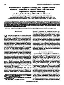
analysis in [11] and [17], the closed-form expression for the -component of the source field depends on the specific region with respect to the axial distance and is given in general form by (2) where Fig. 1. Cylindrical coil of rectangular cross-section above a three-layered conductor system.
(3) The other terms of the integrand include the Bessel function and the integral
with application to SQUID NDE have been given in [18] but for the limiting case of a filamentary loop. B. ETREE Modeling and Solid-State Magnetic Field Sensing
(4) and the term is the source current density of the coil with denoting the number of wire turns. The -component of the field change due to the layered system is given by the integral expression
(5) where is essentially a reflection coefficient that describes the effect of the layered system. In the context of this paper, the three-layered system of Fig. 1 has been modeled. The model comprises a top layer having conductivity , relative magnetic permeability and thickness , a middle layer having conductivity , relative magnetic permeability and thickness ; and a bottom layer extending to infinity and having conductivity and relative magnetic permeability . In this case [13]
The numerical calculation of (2) and (5) may present some numerical difficulties, because either appropriate cut-off regions have to be set or automatic integration routines have to be utilized. These difficulties are overcome by a novel approach that replaces the integral expressions with series ones after truncating the solution region at an appropriate radial distance . Although the number of series expressions and the radial distance bring about computational errors, the error can be more readily controlled [15]. This approach has been used for the solution of many canonical eddy-current NDE problems and is called the TREE method. Following the analysis in [12] and [13], the following series expressions can be derived for the source magnetic field as well as for the field change at a particular point above the layered conductor:
(11)
(6) (12) where (7) (8) For a two-layered system, this can be modeled, for example, by setting , the reflection coefficient simplifies to
where the eigenvalues of equation
are now the positive roots of the
(13) or equivalently
(9)
(14)
whereas for a one-layered system (essentially a conductive halfspace modeled by setting ) it reduces to
The remaining terms are similar to those in the integral expressions; also, the index now refers to a particular summation term. Equations (11) and (12) offer a number of advantages as compared to (2) and (5), which are similar to those for the coil impedance presented in [19]. Moreover, they can be readily computed with moderate effort using mathematical packages such as Mathematica or Matlab.
(10) In (6)–(10), and . Similar expressions for the two-layer case, simulating a conductive plate
4012
IEEE TRANSACTIONS ON MAGNETICS, VOL. 43, NO. 11, NOVEMBER 2007
Mathematica has intrinsic routines for calculating Bessel function roots and the integral in (4). Thus, the numerical computation of the magnetic field as a function of frequency for a logarithmic frequency scan, takes no more than 1 s in a typical Pentium processor computer. It is worth noting that the solid-state magnetic field sensor, like the Hall device, does not measure the magnetic field at a particular point but that within the volume of its sensing element, because the dimension of the sensing element cannot be negligible with respect to the coil size. Therefore, (11) and (12) should be modified to derive the formulation of averaging magnetic field within the volume of Hall sensing element. It was assumed that the length and thickness of the element are and , respectively. First, the element in cubic geometry was converted into cylinder while its volume and thickness were kept unchanged. If the modified element in cylindrical geometry has the radius of and thickness of , by taking the volume integration, (11) and (12) can be rewritten as
(15)
The closed-form expressions of (18) and (19) are the formulations of ETREE to predict the magnetic field signals picked up by Hall devices. depends on the excitation frequency. In (19), only the When the excitation frequency sweeps within a certain range, has to be computed for every frequency while the only other terms are calculated only once. This results in substantial saving of computation time. Such saving is significant, because what is required in various inversion schemes is a fast-forward solution in terms of the frequency. III. FEM SIMULATIONS In addition to analytical modeling, eddy-current phenomena were also investigated via numerical simulations including FEM [21], finite network [22], [23], and so on. The FEM simulations were carried out to compare the accuracy and efficiency of ETREE. Two-dimensional axisymmetric models were built up for different layered structures. The FEM program was written in Matlab in conjunction with the commercial FEM simulation package Comsol Multiphysics [24]. Because FEM is a mesh-dependent method, dense mesh was chosen especially within the cross sections of the coil, Hall sensing element, and layered samples to obtain the converged results. In balance of computation time and simulation accuracy, the number of elements was set as 61 805; the relative errors between FEM and ETREE are less than 0.05%. IV. COMPARISON OF RESULTS AND DISCUSSION
(16) where . To derive the integral of Bessel function lowing identity [20] can be used:
, the fol-
(17) Consequently, the modified formulations for computing the mean magnetic field and its variation due to layered conductors can be written as
(18)
(19) Equation (19) can be written in a more compact form as
(20)
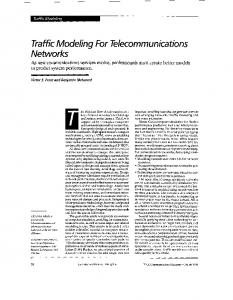
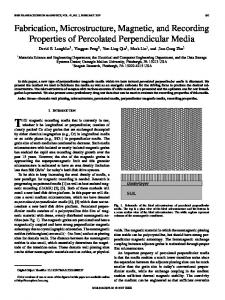
A. Experimental Study The -component of the magnetic field above a layered planar structure was measured using a Hall sensor and the measurements were compared with both analytical and numerical results. The schematic of the experimental setup is shown in Fig. 2 along with a close-up image of the excitation coil presented in Fig. 3. A waveform generator and a power amplifier were employed as the coil power source to power the excitation coil with sinusoidal current from 20 Hz to 10 kHz. Since the coil power source was a constant voltage source which kept the output peak-to-peak voltage at preset voltage for variable frequencies, the current through the excitation coil varied with different excitation frequencies. Both the magnitude and frequency of the resultant excitation current were measured in parallel to the quantification of magnetic field during the experiments. The excitation data were imported into ETREE and FEM simulations for theoretical study. In addition, to avoid the coil thermal drift during excitation, the current amplitude was set at less than 91.5 mA (maximum value at lowest frequency) within the frequency range. The Hall device (SS495A) was used to evaluate the -component of the overall magnetic field and placed at the center of the excitation coil. A circuit power source was adopted to power the Hall device as well as the signal conditioning circuit where an INA111 high-speed FET-input instrumentation amplifier was chosen. The preprocessed signals were then obtained by a data acquisition card installed in a computer and controlled by a signal acquisition and processing program implemented in LABView.
LI et al.: MAGNETIC FIELD-BASED EDDY-CURRENT MODELING FOR MULTILAYERED SPECIMENS
4013
Fig. 2. Schematic experimental setup for EC.
TABLE I DIMENSION AND PROPERTIES OF THE LAYERED STRUCTURE
TABLE II COIL PARAMETERS
After destructive investigation, the dimension of the sensing element was found to be 0.91 0.46 mm in Hall device SS495A. Because its center was located at the center of the excitation coil, 0.5 mm above the surface of specimen, the second and third expressions of (3) were employed in ETREE modeling. B. Two-Layer Case Study The EC response to a two-layered specimen which consisted of an aluminum plate as the upper layer and air below the plate as the bottom layer, was first investigated via simulations of ETREE and FEM as well as experimental study. The frequency of excitation was swept from 20 Hz to 10 kHz. The comparison is illustrated by plots in Figs. 4(a) and 5(a). Fig. 3. Excitation coil with Hall device.
The dimensions and properties of the layered structure and the EC excitation coil employed in simulation and experimental study are shown in Tables I and II, respectively. The lift-off of the excitation coil was determined by the actual thickness of the coil holder. The DC inductance and resistance of the coil were measured using an inductance–capacitance–resistance (LCR) Bridge with a frequency of 100 Hz. The measured coil inductance showed a discrepancy of 1% from the theoretical value of 19.6 mH. The resonance frequency of the excitation coil was 23.6 MHz.
C. Three-Layer Case Study Following the investigation of EC response to a two-layered specimen, a three-layered specimen was introduced, which comprised an aluminum plate as the upper layer, a Brass plate as the medium layer, and air as the bottom layer. At each frequency, the -component of the magnetic field was obtained at the center of the coil on the coil axis through the experiments, ETREE and FEM. The comparison is shown in Figs. 4(b) and 5(b). D. Discussion 1) Accuracy: In general, the predicted magnetic field signals over the excitation frequency range via ETREE and FEM
4014
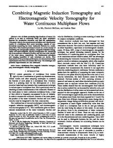
Fig. 4. Magnetic field versus excitation frequency in logarithmic scale for (a) two-layered sample and (b) three-layered sample.
show good agreement with the experimental results. The cross differencebetweenexperimentaltest,analyticalmodel(ETREE), and numerical model (FEM) is within 1%, which is at almost the same level as conventional modeling for impedance signal [11], [19], [25]. The analytical approach provides the compact closed-form expressions of magnetic field signals, which is entirely mesh-independent. In contrast, a highly dense mesh was chosen to obtain converged results when FEM simulations were conducted, which made FEM a lot more time consuming than ETREE. Unlike coil based impedance signals, the phase variation of the magnetic field was not investigated and the results are presented in terms of the magnitude of the magnetic field. However, there is very small discrepancy between the predicted and experimental results, as can be seen in Fig. 4. In the low-frequency range from 20 Hz to 1 kHz, where the influence of eddy current generated inside the conductive specimen was much smaller, the deviation of predicted values from the experiment was caused by the difference in DC inductance of the excitation coil between theory and experiment. In addition, the in-
IEEE TRANSACTIONS ON MAGNETICS, VOL. 43, NO. 11, NOVEMBER 2007
Fig. 5. Magnetic field per unit excitation current versus excitation frequency in logarithmic scale for (a) two-layered sample and (b) three-layered sample.
trinsic noise of the Hall device is assumed to contribute to the discrepancy. The results of theoretical study, in the frequency range of 1 kHz to 10 kHz, agree well with the experimental results. Nevertheless, the difference between theory and experiment is higher for the three-layer case than the two-layer one. The small difference may be caused by a very small gap (approximately 0.1 mm) between the aluminum plate and brass plate, while in the theoretical model no gap is assumed. In further work, if a thin air layer is modeled between the two conductors, the discrepancy would be cancelled. 2) Computation Time: The computation time is one of the most important factors used in evaluating the efficiency of simulations. Both ETREE modeling and FEM simulation were conducted in a computer with 2.13 GHz CPU and 1 GB RAM. The number of computed frequencies was 21 from 20 Hz to 10 kHz. The time consumed via ETREE and via FEM can be compared from the data shown in Table III. In Table III, ETREE is much more efficient than FEM, even though the FEM simulations were implemented in Matlab to save computation time. Apparently, ETREE exhibits superiority
LI et al.: MAGNETIC FIELD-BASED EDDY-CURRENT MODELING FOR MULTILAYERED SPECIMENS
4015
TABLE III COMPUTATION TIME SPENT ON ETREE AND FEM
over FEM, because ETREE provides the compact closed-form solution to forward time-harmonic problems. Moreover, most parameters in the formulations need to be computed only once over the frequency domain, and this makes the computation of magnetic field equations in form of series expansions very fast. V. CONCLUSION In this work, new models for magnetic field monitoring rather than traditional detection coils were investigated and analyzed via simulations of EC response to a multilayered conductive structure. Based on the results, ETREE has advantages in the solution of TREE for magnetic-sensor-based EC forward problems. The paper also introduces a new innovation by modeling the Hall-effect sensor as having a finite volume. The conclusions are drawn as follows. • A good agreement can be found among ETREE, FEM, and experimental tests, which fulfills the requirements from more and more EC inspection systems using magnetic sensing systems for nondestructive testing and evaluation (NDT&E). • ETREE is mesh-independent and offers closed-form expressions, so magnetic field signals can be derived from different excitation frequencies effectively and accurately. The theoretical modeling method can be beneficial for the design and development of eddy-current NDT&E systems and inverse processes in characterizing of each layer, including conductivity and thickness, that is, the layered structure’s conductivity profile. As a follow-up of the current work, further investigation needs to focus on: 1) investigating magnetic-field-based pulsed eddy-current inspection on layered conductive specimens via theoretical and experimental approaches and 2) extending theoretical modeling to other electromagnetic applications. ACKNOWLEDGMENT The authors thank the EPSRC and the Royal Society, United Kingdom, for funding this research. REFERENCES [1] V. Sundararaghavan, K. Balasubramaniam, N. R. Babu, and N. Rajesh, “A multi-frequency eddy current inversion method for characterizing conductivity gradients on water jet peened components,” NDT&E Int., vol. 38, no. 7, pp. 541–547, 2005. [2] P. J. Huang, G. X. Zhang, Z. T. Wu, and Z. K. Zhou, “Forward model and simulator of thickness measurement of multi-layered conductive structures by eddy current technique,” Chin. J. Sens. Actuators, vol. 18, pp. 1–6, 2005. [3] G. Y. Tian and A. Sophian, “Study of magnetic sensors for pulsed eddy current techniques,” Insight, vol. 47, no. 5, pp. 277–280, May 2005. [4] G. Y. Tian, A. Sophian, D. Taylor, and J. Rudlin, “Multiple sensors on pulsed eddy-current detection for 3D subsurface crack assessment,” IEEE Sensors J., vol. 5, no. 1, pp. 90–96, Feb. 2005. [5] J. R. Bowler and D. J. Harrison, “Measurement and calculation of transient eddy currents in layered structures,” Rev. Progr. Quant. Non-Destruct. Eval., vol. 11, pp. 241–248, 1992.
[6] J. R. Bowler and M. Johnson, “Pulsed eddy-current response to a conducting half-space,” IEEE Trans. Magn., vol. 33, no. 3, pp. 2258–2264, May 1997. [7] R. A. Smith and G. R. Hugo, “Transient eddy current NDE for ageing aircraft-capabilities and limitations,” Insight, vol. 43, no. 1, pp. 14–25, 2001. [8] W. W. Ward and J. C. Moulder, “Low frequency, pulsed eddy currents for deep penetration,” Rev. Progr. Quant. Nondestruct. Eval., vol. 17, pp. 291–298, 1998. [9] C. C. Tai, H. C. Yang, and Y. H. Liu, “Modeling the surface condition of ferromagnetic metal by the swept-frequency eddy current method,” IEEE Trans. Magn., vol. 38, no. 1, pp. 205–210, Jan. 2002. [10] J. R. Bowler, “Review of eddy current inversion with application to nondestructive evaluation,” Int. J. Appl. Electromagn. Mech., vol. 8, pp. 3–16, 1997. [11] C. V. Dodd and W. E. Deeds, “Analytical solutions to eddy-current probe-coil problems,” J. Appl. Phys., vol. 39, no. 6, pp. 2829–2838, 1968. [12] J. R. Bowler and T. P. Theodoulidis, “Eddy currents induced in a conducting rod of finite length by a coaxial encircling coil,” J. Phys. D: Appl. Phys., vol. 38, pp. 2861–2868, 2005. [13] T. P. Theodoulidis and E. E. Kriezis, Eddy Current Canonical Problems (With Applications to Nondestructive Evaluation). Norcross, GA: Tech Science Press, 2006. [14] T. P. Theodoulidis and J. R. Bowler, “The truncated region eigenfunction expansion method for the solution of boundary value problems in eddy current non-destructive evaluation,” Rev. Progr. Quant. Non-Destruct. Eval., vol. 24A, pp. 403–408, 2004. [15] T. P. Theodoulidis and J. R. Bowler, “Eddy current interaction with a right-angled conductive wedge,” Proc. R. Soc. Lond., vol. 461, no. 2062, pp. 3123–3139, 2005. [16] T. P. Theodoulidis, “Model of ferrite-cored probes for eddy current nondestructive evaluation,” J. Appl. Phys., vol. 93, no. 5, pp. 3071–3078, 2003. [17] J. W. Luquire, W. E. Deeds, and C. V. Dodd, “Alternating current distribution between planar conductors,” J. Appl. Phys., vol. 41, no. 10, pp. 3983–3991, 1970. [18] J. R. Claycomb, N. Tralshawala, and J. H. Miller, “Theoretical investigation of eddy-current induction for nondestructive evaluation by superconducting quantum interference devices,” IEEE Trans. Magn., vol. 36, no. 1, pp. 292–298, Jan. 2000. [19] T. P. Theodoulidis and E. E. Kriezis, “Series expansions in eddy current nondestructive evaluation,” J. Mater. Process. Technol., vol. 161, no. 1–2, pp. 343–347, 2005. [20] M. Abramowitz and I. Stegun, Handbook of Mathematical Functions with Formulas, Graphs, and Mathematical Tables. Washington, DC: Natl. Bur. Stand. Appl. Math. Ser. 5.5, GPO, 1970. [21] Y. Li, G. Y. Tian, and S. Ward, “Numerical simulation on magnetic flux leakage evaluation at high speed,” NDT&E Int., vol. 39, no. 5, pp. 367–373, 2006. [22] T. K. Kidane, W. A. Edelstein, T. P. Eagan, V. Taracila, T. N. Baig, Y. C. N. Cheng, and R. W. Brown, “Active-passive shielding for MRI acoustic noise reduction: Network analysis,” IEEE Trans. Magn., vol. 42, no. 12, pp. 3854–3860, Dec. 2006. [23] M. J. Sablik, R. E. Beissner, and A. Choy, “An alternative numerical approach for computing eddy currents: Case of the double-layered plate,” IEEE Trans. Magn., vol. MAG-20, no. 3, pp. 500–506, May 1984. [24] Comsol, User’s Handbook of Comsol Multiphysics, 2006. [25] T. P. Theodoulidis, “End effect modelling in eddy current tube testing with bobbin coils,” Int. J. Appl. Electromagn. Mech., vol. 19, pp. 207–212, 2004.
Manuscript received June 30, 2006; revised July 23, 2007. Corresponding author: G. Y. Tian (e-mail:
[email protected]).