Making the Circular Self-Test Path Technique Effective for Real Circuits F. Corno, P. Prinetto, M. Sonza Reorda Politecnico di Torino Dipartimento di Automatica e Informatica Torino, Italy Abstract* The paper assesses the effectiveness of the Circular Self-Test Path BIST technique from an experimental point of view and proposes an algorithm to overcome the low fault coverage that often arises when real circuits are examined. Several fault simulation experiments have been performed on the ISCAS89 benchmark set, as well as on a set of industrial circuits: in contrast to the theoretical analysis proposed in [PKKa92], a very high Fault Coverage is attained with a limited number of clock cycles, but this happens only when the circuit does not enter a loop. This danger can not be avoided even if clever strategies for Flip-Flops ordering, aimed at reducing the functional adjacency, are adopted. Instead, we suggest that loops can be avoided and fault coverage increased by carefully choosing the initial state, and we present an approach based on Binary Decision Diagrams and Symbolic Techniques to solve the problem.
1. Introduction BIST techniques are nowadays widely used for testing both whole devices and embedded portions like ROMs, RAMs, combinational chunks of logic, and FSMs. A BIST approach to sequential circuits testing has been proposed and deeply analyzed from a theoretical point of view in [PiKr89] and [PKKa92]. The approach, named Circular Self-Test Path (CSTP), is based on substituting all the Flip-Flops in the circuit with special cells, which are then connected to constitute a circular chain. In [POLB88] some experimental results are presented, which partially support the conclusions drawn in [PiKr89]. In the same paper, several heuristics are proposed to effectively implement a par* This work has been partially supported by the ESPRIT BRA 6575 ATSEC and by the MURST 40% project Affidabilità e Diagnostica in Elettronica. Contact address: Paolo Prinetto, Dipartimento di Automatica e Informatica, Politecnico di Torino, Corso Duca degli Abruzzi 24, I10129 Torino (Italy), e-mail
[email protected]
tial BIST approach with lower cost in terms of hardware overhead. A similar approach is described in [Stro88], where a slightly different cell is introduced to provide the possibility of performing additional operations such as connecting cells as a shift register or a feed-back register, or resetting Flip-Flops. Recently, special hardware modifications have been proposed in [AvMc93] to improve the success of BIST when applied to sequential circuits. An attracting point of CSTP is the ease of conversion of an existing circuit, and the test session not needing any higher level test protocol. [Gage93] reports an application of CSTP in an industrial environment. The main goal of this paper is to make CSTP applicable to test real synchronous sequential circuits. The problem has got a critical importance as a consequence of the wide popularity of synthesis tools in IC designs. The presence of deeply embedded FSMs of increasing size makes test pattern generation even harder. On the other side, most BIST techniques either involve high hardware overhead, as in the case of BILBO [KMZw79], or still have not been proven to be fully reliable, as for the CSTP technique. As a preliminary step, an evaluation is made, from an experimental point of view, to quantify how well the statistical conclusions drawn in [PiKr89] and [PKKa92] are verified. A critical problem is identified, namely the low state coverage due to the circuit entering a loop, which is different from the ones proposed in the literature, and a technique to overcome it is presented. The here presented results demonstrate that some of the conclusions of the analysis of [PiKr89] and [PKKa92] are not applicable to real circuits, that often contradict some assumptions at the basis of the analysis. The main problem appears to be the risk that the circuit reaches an already visited state, thus greatly limiting the number of different values generated on the inputs of the combinational part. In order to evaluate how to reduce this risk, a heuristic algorithm for ordering (and possibly inserting) Flip-Flops has been experimented, whose goal is to reduce the functional
FF Primary Inputs
Primary Outputs
Combinational Logic
FF FF FF
Combinational Logic
FF
FF
FF
FF
FF
FF
a) Original Circuit
FF
b) CSTP Circuit in Test Mode
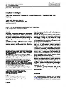
Figure 1: CSTP modification technique adjacency between consecutive Flip-Flops in the chain. As the effectiveness of Flip-Flop ordering appeared to be poor, it is essential to cleverly chose the initial state of the Flip-Flops. Symbolic traversal techniques derived from formal verification are shown to fulfill this goal. Section 2 describes in greater details how the CSTP approach works; Section 3 evaluates the effects of ordering the CSTP cells, and Section 4 presents a solution for finding the optimum initial state. Some conclusions are drawn in Section 5.
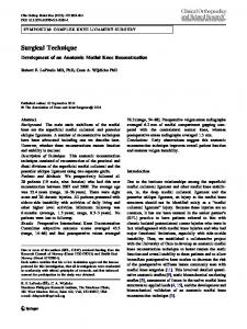
2. CSTP The Circular Self-Test Path approach is based on adding a special cell (hereinafter denoted as CSTP cell) to every Primary Input (PI) and Primary Output (PO) of the circuit (Input and Output Flip-Flops) and transforming the existing Flip-Flops (State Flip-Flops) into CSTP cells (Figure 1). A sample CSTP cell is shown in Figure 2. It is fully transparent during normal operations, and transforms each Flip-Flop into an element of a Feed-back Shift Register while in Test Mode. In this case, the feed-back value comes from one output of the combinational logic, which in turn is fed by the output of the cell when State Flip-Flops are considered. The EXOR gate is omitted in Input Flip-Flop cells.
During the Test Phase, a scan chain is thus created, connecting all the Flip-Flops in the circuit: the chain acts as a non linear feedback shift-register, due to the fact that the State and Output Flip-Flops are fed with the EXOR of the values coming from the preceding Flip-Flop in the chain and from the combinational part of the circuit. The chain thus simultaneously performs the tasks of generating patterns for the combinational part and compressing the corresponding outputs. In other words, it acts both as a Generator and a Compressor. At the end of the test session, the values in the chain constitute the signature of the circuit, and can be scanned-out to detect possible faults. Provided that patterns are randomly generated and compression is prone of aliasing effects, the solution is effective in terms of both hardware overhead and performance speed. A different CSTP cell has been proposed in [Stro88], which allows four different operations to be performed: normal operation, reset, shift, and exor between the preceeding cell’s value and the data input. In order to better understand how well the scan chain performs the two tasks during a test session lasting for T clock cycles, the following parameters are significant: • The number D of different states reached by the circuit, where a state is a value assumed by the Flip-Flops in the CSTP circuit; in the best case,
the circuit reaches a new state at each clock cycle. On the opposite, if at a given time, the circuit’s state is equal to a previously reached one, then the circuit enters a loop, and the number of reached states (as well as the Fault Coverage) remains unchanged no matter the test length. • The number A of activated faults, where a fault is defined as activated if it caused a value different from the good one on at least one Flip-Flop during at least one clock cycle. Due to the aliasing effect typical of compressors implemented as feed-back shift registers, A is always greater (or equal) than the number FD of faults detected at the end of the test phase. Comparing these quantities to the number of faults in the fault list, F, one obtains the aliasing-free fault coverage A / F and the attained fault coverage FC = FD / F. From the logic
Normal/Test
S MPX From the previous cell
To the following cell
Q
D D-type Flip-Flop
Clock
To the logic
Figure 2: CSTP cell for the State Flip-Flops In [KrPi89], several Observations are stated, which probabilistically define the performance of the CSTP approach. They guarantee that adopting a test running time a few times longer than the exhaustive one, the state coverage becomes independent of the initial state of the circular path. Moreover, any possible correlation between the lines feeding the path elements does not affect the state coverage; therefore, the ordering of Flip-Flops inside the path becomes negligible. In [PKKa92] the authors provided the following formula, which is able to predict the Expected Fault Coverage (EFC) of CSTP in terms of the topological parameters of the circuit: T −P − k +1 EFC = 1 − e 2 (1 − 2 S ) , where T is the length of the Test Sequence, P is the number of Flip-Flops in the circular path, k is the
number of inputs of the combinational logic, and S is the signature length. If all the Flip-Flops in the chain are scanned-out at the end of the test session, then S = P. From the formula above, one can deduce that an acceptable fault coverage can be reached only when the number T of clock cycles is at least comparable with 2k+1. Otherwise, the Expected Fault Coverage is very low. The above results have been obtained under the hypothesis that the configurations assumed by the FlipFlops in the chain are equally likely and independent. Unfortunately, this assumption is never verified, as it is clear that, given an ordering of the Flip-Flops in the chain, and an initial state, each state is either reachable (with probability one), or unreachable. In other words, the probabilistic approach loses any practical meaning when considering the behavior of CSTP circuits. In order to experimentally confirm the last statement, we transformed some circuits according to the CSTP technique and performed a set of fault simulation experiments aimed at evaluating the real correctness of the above observations and formulæ. Two sets of circuits have been considered: the former is composed of the ISCAS89 circuits [BBKo89], the latter of several circuits coming from ITALTEL, the Italian Telecom Company (their characteristics are summarized in Table 1). Circuit FSM2 FSM3 FSM4 FSM6
#PIs #POs #gates #FFs 10 3 397 9 4 1 49 5 8 10 205 8 6 2 95 4 Table 1: ITALTEL circuits
For each CSTP circuit the final Fault Coverage (FC), the number of reached states D, and the percentage A/F of activated faults have been computed; all the experiments have been performed starting from the all-0s state, and last for T clock cycles; the circular path is composed by all the Input, Output and State Flip-Flops, in that order. The results for T = 5,000 are reported in Table 2. As far as the results in Table 2 are considered, several facts are worth to be noticed: • The final Fault Coverage FC is influenced by the number of reached states much largely than by the Aliasing phenomenon. This is particularly critical for some circuits (shown in bold face), where D