IEEE TRANSACTIONS ON SIGNAL PROCESSING, VOL. 62, NO. 4, FEBRUARY 15, 2014
939
Maneuvering Target Detection via Radon-Fractional Fourier Transform-Based Long-Time Coherent Integration Xiaolong Chen, Jian Guan, Member, IEEE, Ningbo Liu, and You He
Abstract—Long-time coherent integration technique is one of the most important methods for the improvement of radar detection ability of a weak maneuvering target, whereas the integration performance may be greatly influenced by the across range unit (ARU) and Doppler frequency migration (DFM) effects. In this paper, a novel representation known as Radon-fractional Fourier transform (RFRFT) is proposed and investigated to solve the above problems simultaneously. It can not only eliminate the effect of DFM by selecting a proper rotation angle but also achieve long-time coherent integration without ARU effect. The RFRFT can be regarded as a special Doppler filter bank composed of filters with different rotation angles, which indicates a generalization of the traditional moving target detection (MTD) and FRFT methods. Some useful properties and the likelihood ratio test detector of RFRFT are derived for maneuvering target detection. Finally, numerical experiments of aerial target and marine target detection are carried out using simulated and real radar datasets. The results demonstrate that for integration gain and detection ability, the proposed method is superior to MTD, FRFT, and Radon-Fourier transform under low signal-to-clutter/noise ratio (SCR/SNR) environments. Moreover, the trajectory of target can be easily obtained via RFRFT as well. Index Terms—Across range unit (ARU), Doppler frequency migration (DFM), long-time coherent integration, maneuvering target detection, Radon-fractional Fourier transform (RFRFT).
I. INTRODUCTION
W
ITH the development of science technology, especially the highly maneuvering target and stealth technique, there is a growing need for robust and effective detection of moving target, which is very meaningful for modern radars to improve their detection performance [1]–[3]. The complexity of target detection is not only related to the target itself, but also influenced by the electromagnetic environment and clutter background. There are various kinds of weak moving targets, which Manuscript received June 23, 2013; revised October 17, 2013 and December 17, 2013; accepted December 24, 2013. Date of publication January 02, 2014; date of current version January 20, 2014. The associate editor coordinating the review of this manuscript and approving it for publication was Prof. Maria Sabrina Greco. This work was supported in part by the National Natural Science Foundation of China under Grants 61179017, 61201445, 61002045, and 61302008, and by the special funds of Taishan Scholars Construction Engineering of China. The authors are with the Department of Electronic and Information Engineering, Naval Aeronautical and Astronautical University, Erma Road 188, Yantai, Shandong 264001, P. R. China (e-mail:
[email protected];
[email protected]). Color versions of one or more of the figures in this paper are available online at http://ieeexplore.ieee.org. Digital Object Identifier 10.1109/TSP.2013.2297682
can be categorized into the following four kinds: 1) Small size target with weak radar returns, such as the yacht, periscope, and the unmanned aerial vehicle (UAV), etc.; 2) Low-observable stealth target with low radar cross section (RCS), such as the stealth speed boat, cruise missile, and hypersonic aircraft, etc.; 3) Remote target or target in strong clutter with low signal-toclutter/noise ratio (SCR/SNR); 4) High-speed or highly mobile target with limited available energy, such as jet fighter, missile, and fast patrol boat. The above four kinds of targets can be summarized as “far-range, low-observable, and highly maneuvering” targets. They share a lot in common that both in time and frequency domain, the SCR/SNR is too low to compete with clutter and electronic interference, resulting in poor detection performance [4]. It is well-known that the detection performance and SCR/SNR of radar returns can be improved significantly by means of long-time integration among different sampling pulses [5], [6]. However, for the traditional mechanical scanning radar, the dwell time of beam at target depends on the rotating speed and the number of pulses for integration is limited accordingly. The invention of digital phased array radar (DPAR) makes it possible for long-time observation and integration of target. The radar is equipped with phased-array antenna using digital beam forming (DBF) technology [7], which can transmit multiple beams to cover wider space. The newly developed high range resolution (HRR) radar systems will also provide accurate measurement of range, target recognition and resistance to countermeasures [8], [9]. Therefore, the direction of beam can be controlled arbitrarily and the dwell time is prolonged. Based on the principle that whether phase information of radar returns is used or not, the long-time integration methods can be divided into incoherent integration and coherent integration. The typical methods of the former integration include the envelope interpolation, replacement, and compensation method, dynamic programming technology, maximum likelihood method, and classical Hough transform (HT) based method [10]. The HT can efficiently utilize data from a user-selected number of radar dwells or scans in the detection process to achieve a higher level of performance. Moreover, the track-before-detection (TBD) technique is proposed based on HT, which realizes the long-time integration [11]. The incoherent integration methods don’t require strict coherence of radar system, which are easy to realize. Some hybrid methods combing coherent and incoherent integration are also
1053-587X © 2014 IEEE. Personal use is permitted, but republication/redistribution requires IEEE permission. See http://www.ieee.org/publications_standards/publications/rights/index.html for more information.
940
IEEE TRANSACTIONS ON SIGNAL PROCESSING, VOL. 62, NO. 4, FEBRUARY 15, 2014
proposed [12]. However, the disadvantage is that they cannot compensate the phase fluctuation resulting in low integration gain and thus fail to be applied in low SCR/SNR environment. The coherent integration technique employs motion status and Doppler information, which can strengthen the target’s energy greatly. However, it mainly encounters the following two problems. One is that for the high-speed target and the refined radar range resolution, the target’s envelope may easily walk across several range bins, which is known as the across range unit (ARU) effect [5]. In this case, the energy of target is distributed in range direction after integration and the ARU problem will get worse with faster target’s velocity. Hence, the widely used moving target detection (MTD) method, which employs Doppler filter bank to improve clutter rejection and target detection within one range bin, becomes invalid. On the other hand, for the accelerated or high-order motion, the time-range shows curvilinear relation and Doppler frequency is no longer constant during the integration time, e.g., the aircraft, missile, fast patrol yacht, and rotated target with micro-motion [13]. The time-varying Doppler would exceed radar frequency resolution, which is called the Doppler frequency migration (DFM) [6]. The scattered energy in frequency domain will decrease the integration gain accordingly. To deal with range migration, the existing methods include the envelope correlation, e.g., cross-correlation, minimum entropy, and peak tracking based methods. However, in case of low SCR/SNR environment, we cannot obtain good results of envelope alignment due to the poor correlation among adjacent pulses. A popular method named keystone transform (KT) is introduced to correct the range migration, which involves remapping the slow-time axis in such a way that the radial velocity phase term does not cause the DFM effect [14]. One needs to know the Doppler ambiguity factor of the target. Besides, it cannot correct range curvature due to the radical acceleration of target. Recently, a novel Radon-Fourier transform (RFT) is proposed by Xu, et al. [5], to realize the long-time coherent integration for the moving target with ARU range walk. The RFT can effectively overcome the coupling between the range walk and phase modulations by jointly searching along range and velocity directions of moving target. Moreover, it can be applied to space-time processing for wideband DPAR [15]. Nevertheless, it will bring about the integration loss in case of the Doppler migration. Typical methods for solving the DFM effect may be the phase matching (PM) approach [16], De-chirp method, chirp-Fourier transform [17], chirplet transform [18], and fractional Fourier transform (FRFT) based methods [19], [20], etc. The PM approach requires prior information about motion parameters and its performance greatly depends on the parameter estimation precision. The rest methods can eliminate the effects of chirp rate or represent the chirp rate on a rotated time-frequency plane. But their performances are still affected by the limited pulses for accumulation. Recently, sparsity has been proved as a promising tool to signal sparse representation, which can be applied to time-frequency decomposition (TFD) to increase resolution in the time-frequency domain [21]. The matching pursuit decomposition can provide superior resolution but is a more computationally intensive process than the other TFDs [22]. There-
fore, the best way for performance improvement is to consider both the ARU and DFM effects. Yang, et al. [23] combined the envelope interpolation and FRFT. However, this method needs processing step by step and the result of Doppler compensation is affected by the previous the range compensation. Zheng, et al. [24] have proposed a fast parametric detection method for high-speed target, which utilizes the joint frequency-domain scaling pulse compression processing and temporal self-correlation KT method to compensate range migration and Doppler frequency ambiguity simultaneously. Unfortunately, the searching parameters of these methods are complicated and not suitable in low SCR/SNR environment. Motivated by the previous work, we develop a generalization of MTD, RFT, and FRFT, called the Radon-fractional Fourier transform (RFRFT) in this paper. It can not only eliminate the DFM effect by selecting proper rotation angle but also achieve long-time coherent integration without ARU range walk. The remaining of the paper is organized as follows. In Section II, the maneuvering target model is considered and established. Section III gives an overview of two methods for coherent integration, that is, the traditional MTD and the RFT. The pros and cons of each method are also discussed. Also, the principle of RFRFT is given and some properties are shown and proven. Then, in Section IV, the likelihood ratio test (LRT) detector of RFRFT is derived. We also present the detailed detection procedure with performance analysis. Section V shows the results of numerical simulations with real radar data, which support the claim that the proposed RFRFT long-time coherent integration method can compensate for range and Doppler migration and improve radar detection performances. The last section concludes the paper and presents its future research directions. II. MANEUVERING TARGET MODEL The maneuvering target of interest is assumed to be an isotropic and nondispersive point scattering object, that is, the point-scattering model. Also, the Doppler modulation from radar movement has been removed via motion compensation, regardless of the shipbone or airbone platforms. To obtain high range resolution profiles (HRRPs) [9] and reduce the effective bandwidth, a radar transmits the normalized linear frequency modulated (LFM) pulse, which has the form (1) where
,
is the radar carrier fre-
is the chirp rate of LFM signal with quency, and bandwidth and pulse duration . Then, the echo signal from the target at time can be represented as
(2) where is the target backscatter coefficient, the time delay is , is the speed of light, is the radar line-of-sight (RLOS) range as a function of slow-time , which measures the time from pulse-to-pulse within a coherent pro-
CHEN et al.: MANEUVERING TARGET DETECTION VIA RADON-FRACTIONAL FOURIER TRANSFORM-BASED LONG-TIME COHERENT INTEGRATION
cessing interval (CPI). Note that the radar return is a function of both slow-time and fast-time , the time measuring the listening period following a pulse transmission. Normally, the maneuvering target has high-order motions, such as acceleration, jerk motion, etc. In order to achieve high detection probability in noise and clutter environment, coherent integration during the pulse repetition interval (PRI) is necessary. Fortunately, the integration time can be arbitrarily controlled using the modern radar such as the phase array radar. The rectangular coordinate system is established with the origin located at the position of radar. Suppose a target is moving towards radar with at . Its velocity is decomposed into radial and tangential components and only the radial one is considered. Then, the range walk is a polynomial function of time and can be expanded into Taylor series as
(3) After the demodulation process via the reference signal, the intermediate frequency (IF) signal is obtained as
(4) where ‘ ’ denotes complex conjugation. Then, the pulse compression (PC) is performed, and (4) can be rewritten as (5) where is the complex amplitude of the echo. Equation (5) indicates that the target’s envelope has been shifted away from its original position due to its motion, and this offset is proportional to its true Doppler frequency. Also, it is noted that the target envelope changes with the slow time after PC. When the offset exceeds the range resolution, that is, , the range migration effect would occur. Moreover, when the target moves nonuniformly, the envelope of returned signal after PC will not only cause the ARU effect, but also follow with range curvature, which may be more obvious with the acceleration increment and range bin decrement. Actually, the range curvature of maneuvering target results from the exponential term of (5), that is, . According to the Weierstrass approximation principle, radar return of a maneuvering target can be approximated as enough order polynomial phase signal and for a target with complex motion during the finite observation time, LFM signal can be regarded as a first-order approximation [13]. Then the target only has an initial radial velocity and a constant acceleration . Higher order motion terms, such as jerk have little influence on the . Therefore, the signal phase of a point target depends on three quantities: , , and , and the expansion of the Doppler spectrum can be approximated as (6)
941
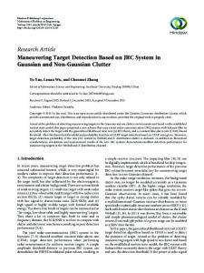
Fig. 1. Diagram of coherent integration processing. (Here we give an example of the uniformly accelerated motion of a missile target and compare the integration time of MTD, FRFT, RFT, and RFRFT.).
where is the wavelength, is the central frequency of Doppler, and is the chirp rate due to the acceleration. From the above analysis, radar return from a maneuvering target with constant acceleration or high order terms can be modeled as a LFM signal. Also, the Doppler frequency of a remote moving target or high-speed target is usually timevarying during the long-time coherent integration, which can be regarded as a LFM signal as well. The acceleration will lead to range curvature and Doppler broadening. If the quantities exceed the Doppler resolution of the radar system, that is, , it would come across the DFM effect. Hence, the target’s motion has an impact on its radar returns during fast-time and slow-time, that is, the time delay of envelope and the Doppler modulation in the complex exponential function of phase, causing the range and Doppler migrations, respectively. III. PRINCIPLE OF RADON-FRACTIONAL FOURIER TRANSFORM A. The Radon-Fourier Transform We perform the Fourier transform (FT) of (5) during the slowtime in order to accumulate the target’s energy coherently. The process is shown as follows (7) , the Suppose a uniform linear motion, that is, above coherent integration in one range bin is the well-known MTD method, which is also regarded as a Doppler filter bank. The Doppler shift can be determined by the maximum value of different filters. Unfortunately, it is difficult to further improve the integration gain of MTD due to the limited target’s resident time in a single range bin, which is shown in Fig. 1. Also, in case of nonuniform motion, the polynomial phase of radar returns related to the target’s motion status will make the FFT-based MTD method invalid. Therefore, the traditional short-time integration procedures, that is, PC within fast-time and MTD during a CPI, are not the optimal approaches for long-time integration in case of the ARU effect.
942
IEEE TRANSACTIONS ON SIGNAL PROCESSING, VOL. 62, NO. 4, FEBRUARY 15, 2014
Based on the coupling relationship of radial velocity, range walk, and Doppler frequency of a moving target, RFT is proposed to realize the long-time coherent integration for a target with range walk, which may quite helpful for the detection of high-speed target [5]. The range migration of (5) is plotted with red dotted line in Fig. 1, which is determined by the and . Then the standard RFT is defined as [5] (8) is a two-dimensional complex function dewhere fined in the plane, , and is a known constant. RFT can extract the observation values in the two-dimensional range versus slow-time plane according to the motion parameters and finally accumulate the target’s energy as a peak by integrating these observations with discrete FT. The RFT of (5) can be represented as
(9) From (9), the RFT is essentially a filter bank with different inputs and outputs. Compared with the MTD method in (7), the integration time of RFT is not limited by the target radial velocity and range resolution, but related to the target’s motion, illuminating time, and the needed SNR gain. Therefore, the RFT is not subject to the ARU effect and more pulses can be coherently integrated within longer time, which is shown in the lower left part of Fig. 1 (red dotted line). It is clear that the Doppler filter function of RFT is identical to that of MTD, which is more suitable for processing uniformly accelerated rectilinear movement. However, the effective integration time along with the straight line (colored in red) may be limited by the range curvature due to accelerated or high-order motion. At the same time, the acceleration will make both Doppler and envelope mismatch between the real echoes and the searching parameters of RFT. Therefore, the accumulated peaks in RFT domain will be broadened and the coherent integration gain will be inevitably decreased, accordingly. Definition of RFRFT It can be deduced from (5) that, after demodulation and PC, the phase of radar return is modulated by both velocity and acceleration, and the Doppler can be approximated as a first order polynomial. As a result, we need to compensate the quadratic phase term to improve the outputs of RFT for higher integration gain, and use some method to achieve the energy accumulation of LFM signal. In Fig. 1, when a target moves nonuniformly, the range curvature happens (plotted with black curve) and both the MTD and RFT method fail to accumulate the target’s energy by searching the original straight line. Compared with the FT, the FRFT is more flexible for processing nonstationary signal due to an additional degree of freedom, that is, rotation angle. The FRFT has included a quadratic form (chirp form) in its kernel function, which makes the LFM signal accumulated as an impulse in the proper FRFT domain (FRFD) [25]. However, the performance of
FRFT is also influenced by the range migration with limited integration time. We borrow the idea of RFT and FRFT and propose a novel transform known as the RFRFT to realized long-time coherent integration for the maneuvering target. Without loss of generality, the definition of RFRFT may be given as follows. Suppose that is a two-dimensional complex function defined in the plane and the line equation representing accelerated or high-order motion is used for searching lines in the plane. Then the RFRFT is defined as
(10) denotes the operator corresponding to the RFRFT of where angle , and the transform kernel is given by
(11) where . The parameters , and are all involved, which have the explicit physical meanings. Specifically, considering (5), its RFRFT may be given as
(12) The transform angle can be calculated by , and is the transform order determined by the searching acceleration after dimensional normalization
(13) where is the scale factor for dimensional normalization and denotes the sampling frequency. When , that is, the frequency domain, the estimated acceleration equals to zero, and then the RFT is the special case of RFRFT. Furthermore, when , the RFRFT actually acts as the FRFT integration component. For comparison, the Radon transform (RT) is also given, which accumulates the signal amplitude along a straight line defined by distance (radius) from the origin and angle of inclination formed by the perpendicular to the line, [26]
(14) , , , . Interestingly, the RFRFT has similar parts as RT and they both use the signal along target’s trajectory. The main difference lies in the way of accumulation, coherently or incoherently. Therefore, the proposed transform is named as RFRFT, and it will definitely outperform the existing methods in complex environment via relatively long-time coherent integration. where
CHEN et al.: MANEUVERING TARGET DETECTION VIA RADON-FRACTIONAL FOURIER TRANSFORM-BASED LONG-TIME COHERENT INTEGRATION
It is easily seen from (10) that the RFRFT is a linear transform, which is not influenced by the cross-term interference. Fig. 1 gives the diagram of coherent integration processing using MTD, FRFT, RFT, and RFRFT. The differences and advantages of RFRFT compared with the others are as follows: 1) The RFRFT combines the merits of RFT and FRFT, so it not only has the same integration time as RFT but also works well as a useful tool for nonstationary and time-varying signal processing; 2) The kernel of RFRFT is introduced to act as a FRFT integration component, which can compensate the phase fluctuations among different pulses due to the high-order motion and generate the ultimate coherent peak; 3) The RFRFT can be regarded as a special Doppler filter bank composed of filters with different transform angles, which can simultaneously compensate and represent the velocity and acceleration; 4) Since the integration time of RFRFT is much longer than MTD and FRFT, the integration gain and detection performance will be further improved.
943
can be expressed on According to (17), the initial signal a basis formed by the set of , which are orthonormal and composed of complex exponentials with chirps. This may indicate the ability of Doppler migration compensation. 3) Index Commutativity and Associativity: We are going to apply (10) twice for two orders. We have , which indicates the RFRFT adheres to the index commutativity. The associativity property comes easily from the above result. In fact, it is easy to derive, . 4) Linear Additivity: It can be easily found that the RFRFT is linear, (18) where and are constant coefficients. The linear additivity shows that the RFRFT satisfies the superposition principle, which is favorable to the analysis of multicomponent signals. Also, it can be represented as follows,
B. Properties of RFRFT It is obvious that is the identity operator, that is , and the RFRFT of angle is the input signal itself. Based on this prior information, several important properties of the RFRFT operator are listed below. 1) Rotational Additivity: Firstly, the kernel of RFRFT has the rotational additivity property, which indicates that the successive applications of are equivalent to a single kernel whose order is equal to the sum of the individual orders, that is [27] (15) Hence, the rotational additivity property can be easily derived,
(19) 5) Parseval Relation: The Parseval relation is expressed as (20) , . The relation can be easily derived by expressing in the left-hand side of (20) as the inverse transform of and then using the property of Kernel, that is, . If , this equality turns into the energy conservation property where
(21)
(16) This property provides us the solution of the transform between different transform angle RFRFTs. If we calculate several RFRFTs of radar signal, it only requires calculating the RFRFT via (10) for one time and the others via (16), which will help to improve the computational efficiency. 2) Inverse RFRFT (IRFRFT): From the first property, we can also easily conclude that the RFRFT of angle is the inverse of the RFRFT of angle , due to . The IRFRFT is (17)
Another explanation of the Parseval relation and energy conservation property is that the RFRFT is based on a set of orthogonal basis functions. Also, the square amplitude of the RFRFT of a signal is often called the energy spectrum of the signal and can be interpreted as the distribution of the signal’s energy among different search parameters, , , . We can call the Radon-fractional energy spectrum of the signal with angle . 6) Time and Frequency Shift Rule: For functions and all belong to , their RFRFTs are defined as and , respectively. If , then (22) which can be proved by changing the variables in the definition of the RFRFT. If , then the frequency shift property can be proved by that of FRFT (23)
944
IEEE TRANSACTIONS ON SIGNAL PROCESSING, VOL. 62, NO. 4, FEBRUARY 15, 2014
IV. LONG-TIME COHERENT INTEGRATION BASED ON RFRFT In this section, the radar detector for maneuvering target based on RFRFT is firstly derived via the LRT principle, and then the detailed procedure of the proposed algorithm is given. Further performances including the coherent integration time, coherent integration gain, and computational complexity are also analyzed.
Under the signal plus clutter condition, that is, hypothesis , and are also complex Gaussian distributed, whose expectations and PDF are
(30)
A. LRT Detector Based on RFRFT Generally, detecting maneuvering target via RFRFT can be represented as a binary hypothesis test [28], so the maneuvering target detection model after RFRFT in the background of complex white Gaussian noise is a typical binary hypothesis
(31) Then the envelope
obeys to the Rice distribution
(24)
(32)
, are the RFRFT of target and where Gaussian noise respectively with angle , is the mixture of thermal noise and prewhitened clutter. is a complex vector decomposed into real and imaginary part and . The amplitude of is
where represents the modified Bessel function of the first kind. Therefore, the LRT detector can be obtained
(25)
(33) Since is the monotonic increasing function, variable can be taken as the test statistic. As a result, target can be declared according to the principle
where represents the complex real operator. The covariance matrix of random variables is given as (26) is a unit sample function. Then its RFRFT expression where can be calculated via (10)
(34) is the LRT threshold, which is determined by the where given false alarm and the clutter power. The random obeys to Rayleigh distribution. Therefore, the false alarm probability equals to (35) and the detection probability is
(27) is the noise power. where Under the hypothesis , the complex random vector and obey to the complex normal distribution with zero mean value and variance , and the probability density function (PDF) can be represented as
(28) , then the envelope obeys to Let Rayleigh distribution and its PDF can be acquired [29] (29)
(36) B. Procedure of the Proposed Algorithm Fig. 2 gives the flowchart of the proposed algorithm, which is composed of six steps. The observation values of target in the range and slow-time plane are firstly extracted according to the preset searching area of the possible motion parameters. Then the observation values are matched and accumulated in RFRFT domain by selecting a proper rotation angle and the long-time coherent integration process of the nonuniformly moving target is completed. Using of the amplitude and phase information together, the proposed method can eliminate the ARU and DFM effects simultaneously.
CHEN et al.: MANEUVERING TARGET DETECTION VIA RADON-FRACTIONAL FOURIER TRANSFORM-BASED LONG-TIME COHERENT INTEGRATION
945
where is defined as the required SNR given the false alarm probability and detection probability, is the required minimum SNR for the furthest target detection according to radar parameters, and is the SNR gain after PC, defined as (39) where is the time bandwidth product of transmitted signal, and if radar transmits single frequency signal, then . In case of a mechanical scanning radar, the dwell time of target can be calculated as (40)
Fig. 2. Flowchart of the longtime coherent integration algorithm for maneuvering target based on RFRFT.
Step 1: Carry out the demodulation and PC to accumulate energy within intrapulses. At the coherent radar receiver, the radar returns are sampled in range and azimuth direction. Normally, the sampling interval in range direction equals to the radar range resolution, that is, , to ensure the radar returns of maneuvering target can be completely sampled during the coherent integration time . Then the sampled data are demodulated as using the transmitted signal. The data after PC are stored as a twodimension matrix in range and slow-time domain, , , and denote the number of pulses and range bins, respectively. Step 2: Parameters initialization for long-time integration The coherent integration time , the number of pulses , the range search scope and interval are predetermined according to radar parameters and dwell time of antenna beam. Based on relative prior information such as varieties and moving status of targets to be detected, the expected searching scope of initial velocity and interval , the scope for acceleration and interval are also preset beforehand. Among these parameters, of the proposed method is obtained as follows.Compared with RFT, the integration time of RFRFT can be greatly extended unaffected to the range curvature and DFM effect, and only restricted by the minimum coherent integration gain and dwell time of antenna beam. Assume the relation between and is , where should be within limits of the time required by the minimum coherent integration gain and the dwell time of beam , that is, .
where is the half-power beam width , represents the antenna scanning speed , and is the elevation angle . Whereas the scanning mode of modern DPAR is phase scanning, the direction of beam can be controlled arbitrarily. Under this condition, is only determined by the preset value instead of the antenna beam width. Normally, the value of are fixed the same as in practical applications. The searching scope of range needs to cover the detection area and the interval is equivalent to the range resolution, that is, . Therefore, the number of searching range is , where denotes the round up to an integer operation. We set the searching scope of velocity according to varieties of targets to be detected, and the interval depends on the same as Doppler resolution, that is, . Therefore, the number of searching velocity is . , interval , and searching number are determined in the same way, that is, , . Step 3: Apply the RFRFT to achieve long-time coherent integration among interpulses. Determine the moving trajectory of target to be searched for according to the preset parameters in step 2. (41) where
,
, , , . Extract the dimension data vector for long-time coherent integration in the range and slow-time (azimuth) domain, that is, . ,
,
(42) Carry out the RFRFT calculation of via (10) to compensate range and Doppler migration simultaneously, which finally achieves the long-time coherent integration of the maneuvering target’s energy. The discrete FRFT (DFRFT) of RFRFT with different transform angles can be realized by the decomposition algorithm proposed by H. M. Ozaktas [30]
(37) where
denotes the expected coherent integration gain [5]. (38)
(43)
946
IEEE TRANSACTIONS ON SIGNAL PROCESSING, VOL. 62, NO. 4, FEBRUARY 15, 2014
Fig. 3. Detailed procedure of RFRFT processing.
where is the signal length, denotes the highest frequency component of . The detailed procedure of RFRFT processing is shown in Fig. 3. The observation values are accumulated coherently during long observation time via a general Doppler filter bank with different transform angles. Therefore, the acceleration and initial velocity corresponds to the coordinate in RFRFT domain . Step 4: Go through all the searching parameters and construct detection map in RFRFT domain. Go through all the searching scope of range, initial velocity, and acceleration. Repeat step 3 to obtain the peak value in the two dimensional domain with a certain searching range , and note down the corresponding coordinate. (44) Then, the detecting map in the RFRFT domain can be obtained, , . represented as Step 5: Carry Out the constant false alarm ratio (CFAR) detection to confirm a target. Take the amplitude in RFRFT domain in step 4 as test statistic, and compare with the adaptive threshold for a given false alarm probability. (45) where is the detection threshold. The adaptive threshold is obtained by the reference unit after RFRFT and then the test statistic in the detecting unit is compared with the threshold to confirm a target or not. If the test statistic is smaller than the threshold, there will be no moving target or a target is missed, and then go on to the next detecting unit. We can pick out the peak of the outputs to select the correct one. However, in a cluttered environment, the correct one is usually obtained by the CFAR technology. In real applications, we cannot obtain the optimal detector since the PDF or amplitude distribution of clutter is different from the one we assumed. That is to say, there will be the CFAR loss using real datasets. However, according to the optimal criteria and simple processing, the biparametric CFAR detector employed in the paper, can form the Gaussian distributed test statistic by vast independent identically distributed (IID) samples [31]. Its detection performance doesn’t depend on the distribution of initial samplings whereas relates to the false alarm ratio and the ratio of the mean and standard deviation value. Therefore, we can obtain the similar result with the detection processing in Gaussian background especially using mass of data or long-time observation.
Step 6: Estimate the motion parameters and obtain the moving trajectory. According to the range, initial velocity, and acceleration corresponding to the coordinate of target in RFRFT domain, the motion parameters are estimated. Assume the initial range of detected maneuvering target is , and its corresponding peak coordinate is . Then the estimation method is (46) Therefore, the searching curve determined by these three parameters can be regarded as the estimation of moving trajectory, that is, (47) The following points should be addressed when carrying out the above procedures in real applications. 1) From step 6, it can be seen that the proposed RFRFT algorithm not only can achieve long-time coherent integration of maneuvering target, but also obtain its trajectory via the searching parameters and CFAR detection. If we lower the CFAR detection threshold further, the results of the obtained moving trajectory would be very conductive to the tracking problem of weak target. Therefore, the proposed method can also provide more useful information for target tracking in rather low SNR/SCR environment. 2) In this paper, the radar is supposed to have high range resolution or a DPAR. In this case, the situation of multiple maneuvering targets in the same range bin would rarely happen. Moreover, due to the high speed or mobility of target, the moving trajectories are quite different with different motion parameters. Therefore, it is not common in real applications. However, the proposed algorithm will still be effective for multiple targets using a good method of strong emitter influence removal such as the “CLEAN” method [32], [33]. 3) Doppler ambiguity is also a tough problem when estimating the motion status [34], which further increases the complexity of radar system and implementation. With the searching strategy, the motion parameters of maneuvering target are preset in step 2, and the moving trajectory of target can be determined by searching. If one of the preset searching trajectory is matched with the real condition, the CFAR output is bigger than the threshold. Therefore, we can ignore and avoid the unwanted Doppler ambiguity problem. 4) The proposed RFRFT also has its apparent limitation: it suffers from the computational load due to the searching process, whereas the commonly used MTD and FRFT have their fast implementation methods. The detailed computational complexity will be discussed in the following parts.
CHEN et al.: MANEUVERING TARGET DETECTION VIA RADON-FRACTIONAL FOURIER TRANSFORM-BASED LONG-TIME COHERENT INTEGRATION
947
C. Performance Analysis 1) Coherent Integration Time: The available integration time of a maneuvering target is obviously restricted by the range and Doppler migration. Hence, the integration time of RFT will be influenced by both range curvature and Doppler migration due to the acceleration, which will cause mismatches with Doppler, envelope, real returns, and searching parameters of RFT. Then, the Doppler and range should meet the following conditions, that is, the Doppler expansion due to the possible maximum acceleration of target should not exceed the Doppler resolution and the range curvature should be within range resolution,
(48) From the above restrictions, we have (49) . At the same Generally, is shorter than time, longer integration time will bring about higher Doppler resolution, which may also cause the energy dispersal in frequency domain. Whereas, the proposed RFRFT can effectively deal with the quadratic frequency modulated phase term duet to the ARU and DFM effects. Therefore, compared with RFT, the of RFRFT is not affected by acceleration which may significantly improve the integration gain. 2) Coherent Integration Gain: In the presence of a signal becomes a random in noise environment, the value variable and the peak indicates the presence of a maneuvering target. Using the method similar to [35], we evaluate the output SNR of RFRFT when the input is a single LFM signal. We define the output SNR of the RFRFT at the location as follows (50) and are the RFRFT of the target only and target plus noise, respectively, represents the variance calculation. According to the Appendix, where
(51) is unrelated to the From (51), it can be found that the chirp rate. This is because that the power of signal and noise at the peak location are both proportional to the chirp rate, whereas the is just the ratio of the two, which offsets the impact of chirp rate. When , the output SNR can be approximated by , which indicates the RFRFT acts as the coherent integration with its gain proportional to the number of integrated samples, but with 3 dB loss due to the quadratic detection. Conversely, at low input SNR, the detection performance can be improved by increasing the integration time and the sampling frequency as well, which is the very superiority of RFRFT. When the integration is completed within one range
Fig. 4. Relation between the integration time and the output SNR via (51). , , , .
bin, the detection performance and integration gain are the same as the FRFT method, which can be easily concluded from (51). We give an example of the relation between and in Fig. 4 for different . It is shown that the increases with , and decreases with . Also, in case of a fixed , the integration gain can be greatly improved about 20 dB by extending the integration time, while the detection performance of FRFT is restricted by the limited integration time. Therefore, it is quite meaningful to improve detection performance of weak maneuvering target via RFRFT. 3) Computational Complexity: Although the RFRFT is superior to the MTD, FRFT, and RFT for detection and estimation of a maneuvering target, the improved performance comes at a cost in computational complexity. Specifically, the increased complexity results from several factors: (1) The integration time of RFRFT is much longer than the MTD and FRFT processing, which indicates a larger number of samples involved in computations; (2) The searching parameters of RFRFT are range, initial velocity, and acceleration to find a maneuvering target, which may further increase the computational burden; (3) The general Doppler filter bank in Fig. 3 is also time-consuming due to the DFRFT with multiple transform angles. Fortunately, when the radar system parameters are given and some prior information of targets to be detected can be obtained, the searching area in the parameter space will be limited and the complexity of searching process will be greatly reduced. Also, using some techniques such as the grading iterative search method [20], the RFRFT will save much of the searching time. Since the digital computation of FRFT is efficient and requires only a sequence of FFTs [30], the proposed RFRFT can be implemented by FFT, which can reduce the computational complexity and memory cost to a similar level of the traditional Doppler filter banks processing. However, the fast implementation of RFRFT is still a useful and challenging subject. V. SIMULATION AND EXPERIMENTAL RESULTS In order to validate the superior performances of the proposed RFRFT method on weak maneuvering target detection and clutter suppression, this section gives numerical experiments. We set two kinds of targets in different environments, one is the simulated low-observable aerial targets in noise background
948
IEEE TRANSACTIONS ON SIGNAL PROCESSING, VOL. 62, NO. 4, FEBRUARY 15, 2014
TABLE I SIMULATION PARAMETERS FOR AERIAL TARGET DETECTION.
Fig. 5. Radar returns of two maneuvering aerial targets in the Gaussian noise background. (a) Range versus time plot (The red lines are the true trajectories); . (b) Range-Doppler analysis of radar returns
which are observed by an air-search radar; the other is the weak marine target using an S-band sea surveillance radar (SSR). Also, the RFRFT is compared with the MTD, FRFT-based methods which make use of the coherent information among pulses within one range bin, and the long-time integration method, that is, RFT. A discussion of the noise and sea clutter, and how they impact the detection performances follows, using Monte Carlo simulations. It should be pointed out that the simulated and real radar used in this section are all assumed to have phased-array antennas or work at dwell mode. A. Detection of Maneuvering Aerial Target The experimental parameters of S-band air-search radar are given in Table I. Suppose there are two subsonic flying targets away from radar at the initial distances and 82 Km. The radial initial velocities and accelerations are , , , and . Due to the long distance, the two maneuvering targets are too weak to be observed with the and after PC, respectively. Radar returns of the two maneuvering aerial targets in Gaussian noise background are shown in Fig. 5. Fig. 5(a) gives the range-time image, and the amplitude is normalized. Note that there are two targets at 80.5 Km and 82 Km corresponding to the 2012th and the 2050th range bin, and they are flying away from radar with different velocities and accelerations. The moving trajectories of the two targets cannot be clearly observed in the range-time plot. Therefore, it is quite necessary for long-time coherent integration to improve SNR. For better analysis, their real moving trajectories are given in red lines in Fig. 5(a) and the RLOS distances of the two targets at different times are calculated according to the motion parameters in Table I. Note that during the long flight time (8s), the two targets move across 56 and 112 range bins. The fast speed and acceleration result in range migration with range curvature,
Fig. 6. Detection of maneuvering aerial targets by MTD and RFRFT methods in the Gaussian noise background. (a) STFT spectrum of #1 within one range ; (b) Detection of #1 by MTD ; (c) STFT bin ; (d) Detection of #2 by spectrum of #2 within one range bin ; (e) RFRFT spectrum of #1 , MTD ; (f) Detection of #1 by RFRFT ; (g) RFRFT ; (h) Detection of #2 by RFRFT spectrum of #2 .
and therefore the ARU and DFM effects occur. Moreover, Fig. 5(b) shows the range-Doppler analysis of radar returns with . It can be seen that the energy of targets is improved to some extend via short-time coherent integration. However, the accumulated energy is still distributed among different rang bins and Doppler cells. This is because the uniform motion model might be hard to reflect the velocity changes during a long time. Also, the second target (#2) shows high mobility with more serious DFM effect, which makes its Doppler walk across several resolution units. Fig. 6 compares the detection results of the traditional MTD and the proposed RFRFT method. The MTD method utilizes pulses in one range bin, that is, 256 pulses for #1 and 128 pulses for #2, while the RFRFT can make use of more pulses after ARU and DFM compensation, that is, 1024 pulses for both targets. From Figs. 6(a) and 6(c), the time-frequency distribution in one range bin obtained by short-time Fourier transform (STFT) [36]
CHEN et al.: MANEUVERING TARGET DETECTION VIA RADON-FRACTIONAL FOURIER TRANSFORM-BASED LONG-TIME COHERENT INTEGRATION
949
TABLE II EXPERIMENTAL PARAMETERS FOR SEA SURFACE TARGET DETECTION USING THE SSR.
Fig. 7. Description and analysis of the data recorded by the SSR. (a) Pictures of the environment taken on August 8, 2010. (The upper photo shows the observed moving target and the lower one indicates the sea surface.); (b) Range-Doppler analysis of radar returns.
indicates the time-varying Doppler, which is in accordance with the assumptions. The integration gain cannot be improved obviously due to the limited pulses, and the amplitude of #2 in frequency domain is covered by noise. If there is no prior information about the two targets, they cannot be detected accurately. Figs. 6(b) and 6(d) show the detection results based on MTD, from which false alarm (noise) appears due to the low SNR. Therefore, Figs. 6(a)–6(d) all indicate that the traditional Doppler filter bank, that is, MTD method, cannot completely match with the high order phase of radar returns, which may further deteriorate the integration performance. Figs. 6(e)–6(h) show the results based on the RFRFT method. By setting proper searching parameters, the motion equation of targets can be obtained, and the data vector is extracted for long-time coherent integration in the range and slow-time domain. The energy of #1 is accumulated as an obvious peak in RFRFT domain without dispersive Doppler spectrum. This is benefited from two points, one is the longer integration time and the other is the transform angle, with which the target’s energy can be accumulated better in the corresponding optimal domain. Figs. 6(f) and 6(h) give the detection results of #1 and #2 via RFRFT. The best transform orders are and , respectively, which indicates that the acceleration of #2 is bigger than that of #1, and the peak location in RFRFT domain is related to the initial velocity of target. B. Detection of Maneuvering Target at Sea Robust and effective detection technique of weak moving target in sea clutter is always a challenging subject in the field of radar signal processing. On the one hand, sea environment is complex and changeable, especially in case of high sea state. On the other hand, the long distance or small size of target itself results in rather low SCR of radar returns, which further decrease the detection performance of radar. The detailed information about the SSR dataset is shown in Table II. Fig. 7(a) shows the pictures of environment. The
range-Doppler image of the radar returns after PC is shown in Fig. 7(b), which demonstrate a possible target located at 74 nm. In spite of the large size, its radar returns are still covered by sea clutter and noise due to the long observation distance. It can be seen that the Doppler frequency of target spans lots of Hertz, from to , and the energy distribution in range dimension is not focused, which indicate the nonuniform motion of target with serious ARU and DFM effects. The detection results via the MTD, FRFT, RFT, and RFRFT methods are compared in Fig. 8. The time-frequency analysis is performed on the radar returns of moving target, and the coherent integration results within one range bin is shown in Fig. 8(a). It is still difficult to extract target signal due to the heavy sea clutter and noise components. Fig. 8(c) shows the detection result of MTD, from which we can see the target’s amplitudes in frequency domain are quite close to that of clutter resulting in lots of false alarms. The estimation of the target’s velocity is by selecting the maximum output of the Doppler filter bank. We transform the radar returns into FRFT domain and its FRFT spectrum within one range bin is shown in Fig. 8(b). We can easily find that the target’s energy is accumulated better and by searching for the matched transform angle the best FRFT spectrum is obtained (see Fig. 8(d)). Although the differences of target and sea clutter have been enlarged compared with Fig. 8(c), there are still a few false alarms. This is because that the sea clutter is mixed with noise whose spectrum is uniformly distributed. Also, the acceleration of target is not obvious with a smaller transform angle, which makes it hard to distinguish target, clutter, and noise. Using the preset searching parameters, we know the maximum peak value is located at . Fig. 8(e) gives the short-time RFT (STRFT) spectrum by showing the RFT spectral characteristics as a function of time.
(52) where is a window function. Then the target’s energy can be focused better. However, the integration gain is still affected by the Doppler migration. If the detection results of FRFT and RFT are compared, it can be found that in spite of the longer integration time, the improvement via RFT is not obvious accordingly. This is because that the longer time, the more obvious of the broadened Doppler spectrum, and the target energy will be distributed among different Doppler units. Finally, let us check the performance using RFRFT in Figs. 8(f) and 8(h). By searching for peak value in transform domain among different range bins, the detection map is constructed, which indicates a maximum peak at with . We can see from Fig. 8(h) that during , the RFRFT coherently accumulates the walking envelope and Doppler into a point representing the velocity and
950
IEEE TRANSACTIONS ON SIGNAL PROCESSING, VOL. 62, NO. 4, FEBRUARY 15, 2014
Fig. 9. CFAR processing results via the biparameter detector (a) MTD method; (b) FRFT method; (c) RFT method; (d) RFRFT method.
.
close to that of FRFT, which indicates that when processing the quadratic phase signal, the RFT has integration gain loss in spite of long integration time. Note that the RFRFT achieves the best performance with only two false alarm points and the target is more obvious as decreases. C. Detection Performances Analysis In order to quantitatively analyze the detection performance and SCR improvement by different methods, we compare the normalized difference between the peak of sea clutter and the moving target, which is defined as Fig. 8. Detection of maneuvering targets at sea by MTD, FRFT, RFT, and ; (b) RFRFT methods. (a) STFT spectrum within one range bin ; (c) Detection result of MTD FRFT spectrum within one range bin ; (d) Detection result of FRFT ; ; (f) RFRFT spectrum (e) STRFT spectrum ; (g) Detection result of RFT ; (h) . Detection result of RFRFT
acceleration. The peak of target is more obvious and at the same time, sea clutter and noise are greatly suppressed, which improves the detection performance of radar system significantly. Also, we can obtain the more accurate estimation of motion parameters and trajectory via (46) and (47), and . It should be noted that for convenient analysis and comparison, the coordinates of FRFT and RFRFT, that is, , are converted to accordingly via (6) and (46). Fig. 9 shows the CFAR processing results via the biparameter detector with false alarm probability . Most energy of the maneuvering target has been remained with few false alarms. The performance of MTD method is the worst, and the amplitudes of sea clutter are still higher than the threshold resulting in eight false alarm points. Also, due to the unwanted Doppler migration, the detection performance of RFT is very
(53) and denote the peak of moving target and sea where clutter, respectively. At the same time, we define the SCR in transform domain as follows,
(54) where is the maximum value of the output, denotes the peak location of the target and is the peak width which means the energy extent of target. The is a very important factor which can directly indicate improvement of the SCR as well as the ability of sea clutter suppression. The results are shown in Table III, from which the proposed method can greatly increase the peak differences of sea clutter and moving target from 0.245 using MTD to 0.677 by RFRFT. It is obvious that RFRFT can help improve the about 8 dB compared with the traditional MTD and 3 dB with the RFT.
CHEN et al.: MANEUVERING TARGET DETECTION VIA RADON-FRACTIONAL FOURIER TRANSFORM-BASED LONG-TIME COHERENT INTEGRATION
TABLE III PERFORMANCE AND COMPUTING TIME USING DIFFERENT METHODS FOR SEA SURFACE TARGET DETECTION.
Fig. 10. Detection probability of MTD, RFT, FRFT, and RFRFT detectors for . (a) Gaussian noise background; (b) different integration time Sea clutter background.
Therefore, the marine target can be easily detected and distinguished via the LRT detector of RFRFT in (34) and (45). Under the same condition, the computational complexities of the four methods on average are also shown in Table III. Because of the short time and FFT-based implementations, the MTD, FRFT, and RFT can satisfy the efficiency requirement, whose computing time is less than 1s. However, the proposed method costs more time than the others due to the time-consuming searching process and DFRFT calculations. If several efficient methods mentioned in Section VI are used, the computational complexity will be greatly decreased. The detection performances are further investigated by Monte Carlo trials. We combine the biparameter CFAR detector and the four methods as corresponding detectors, and the Gaussian noise and real sea clutter are added to the maneuvering target returns. Fig. 10 shows the detection probability
951
of the four detectors against different SCR levels and in each case, times of Monte Carlo simulations are done with . Besides, we have considered the influences of different integration time upon the same detector. From Fig. 10(a), several points may be made as follows: 1) Since the number of pulses for coherent integration is limited by one range bin, the detection probabilities of MTD and FRFT detectors will decline sharply in case of the and the signal will be completely covered by noise. However, the two long-time coherent integration detectors, that is, RFT and RFRFT detectors, make use of more pulses for accumulation, which further improve the input SNR. 2) For the same detection probability , the required SNR of RFRFT is 3 dB lower than that of RFT, which indicates the integration gain for DFM compensation. 3) The detection performance increases more slowly with SNR especially when the . Furthermore, there is a cross point of curves between RFT and FRFT. This is because that the RFT fails to deal with range curvature and DFM effect, and the Doppler spectrum expands more obviously as the SNR increases. In this case, the energy of target cannot be well accumulated. The phenomenon is in accordance with the results of SSR Fig. 8. 4) It can be also concluded from the curves of RFRFT with and that longer integration time or higher sampling frequency can help improve the detection performance. We may obtain the similar results under sea clutter environment, which is shown in Fig. 10(b). The detection performance of RFRFT is superior to the others thanks to its ability to deal with range walk, curvature, and Doppler migration. On the condition that the and , the of RFRFT is improved about 20% compared with RFT detector, that is, higher than 80%, which is enough for distinguishing the sea clutter and maneuvering target. Finally, we can come to the conclusion that the novel RFRFT has numerical useful properties and several promising applications in radar signal processing, such as the wideband radar processing, low-observable target detection, high-speed or highly mobile target detection, and clutter suppression. It is of course impossible to cover all of them, so we just give several examples in this paper. VI. CONCLUSION Based on the parametric modeling of a maneuvering target’s motion, it is found that the quadratic term of radar echo due to the accelerated or high-order motion may lead to the broadened Doppler and range curvature during the long integration time. Also the integration gain may decrease due to the range walk. In this paper, we have shown how a generalization of the FRFT and standard RFT can be used to the detection of maneuvering target with accelerated or high-order motion. This generalization is a newly derived representation of so-called the RFRFT, which can deal with the above problems effectively. Some useful properties of RFRFT are derived and its LRT detector employs the
952
IEEE TRANSACTIONS ON SIGNAL PROCESSING, VOL. 62, NO. 4, FEBRUARY 15, 2014
envelope as test statistics. Also, the paper provides detailed performance analysis including the coherent integration time, integration gain, and computational complexity. Finally, numerical experiments using simulated and real radar datasets are carried out and the performances of different detectors are compared. The results show that the RFRFT, being an extension of the MTD, FRFT, and standard RFT, can be used effectively in all situations where these transforms are presently being used. Some gains can be expected in most of these applications because of the long-time coherent integration and the additional degree of freedom (rotation angle) that RFRFT provides us with. The work presented here opens several areas for long-time integration, target detection, and tracking. The future work along this direction is to explore the implementations of the RFRFT in real engineering applications, and the comparison of the RFRFT with the other kind of compensation method for range and Doppler migrations. APPENDIX PROOF OF (51) Suppose is the zero-mean, stationary, white complex Gaussian noise with auto-correlation function (55) According to the discrete calculation method of RFRFT (43), the peak of and the expected value of can be calculated as
(56)
(57) The variance in (50) is
(58) . Then rewrite The input SNR is defined as (50) by substituting (56) and (58), and we obtain the output SNR of RFRFT, that is, (51).
ACKNOWLEDGMENT The authors would like to thank the anonymous reviewers and the editor for their valuable comments and suggestions which significantly improved this paper. REFERENCES [1] D. W. Winters, “Target motion and high range resolution profile generation,” IEEE Trans. Aerosp. Electron. Syst., vol. 48, no. 3, pp. 2140–2153, Jul. 2012. [2] X. L. Chen, J. Guan, and Y. He, “Sea clutter suppression and moving target detection method based on clutter map cancellation in FRFT domain,” in Proc. Int. Radar Conf., Oct. 2011, pp. 438–441. [3] M. D. Xing, J. H. Su, G. Y. Wang, and Z. Bao, “New parameter estimation and detection algorithm for high speed small target,” IEEE Trans. Aerosp. Electron. Syst., vol. 47, no. 1, pp. 214–224, Jan. 2011. [4] X. L. Chen, J. Guan, Y. He, and J. Zhang, “Detection of low observable moving target in sea clutter via fractal characteristics in FRFT domain,” IET Radar Sonar Navig., vol. 7, no. 6, pp. 635–651, 2013. [5] J. Xu, J. Yu, Y. N. Peng, and X. -G. Xia, “Radon-Fourier transform for radar target detection, I: Generalized Doppler filter bank,” IEEE Trans. Aerosp. Electron. Syst., vol. 47, no. 2, pp. 1186–1202, Apr. 2011. [6] R. Tao, N. Zhang, and Y. Wang, “Analysing and compensating the effects of range and Doppler frequency migrations in linear frequency modulation pulse compression radar,” IET Radar Sonar Navig., vol. 5, no. 1, pp. 12–22, 2011. [7] B. Cantrell, J. d. Graaf, F. Willwerth, G. Meurer, L. Leibowitz, C. Parris, and R. Stapleton, “Development of a digital array radar (DAR),” IEEE Aerosp. Electron. Syst. Mag., vol. 17, no. 3, pp. 22–27, Mar. 2002. [8] Y. Luo, Q. Zhang, C. W. Qiu, X. J. Liang, and K. M. Li, “MicroDoppler effect analysis and feature extraction in ISAR imaging with stepped-frequency chirp signals,” IEEE Trans. Geosci. Remote Sens., vol. 48, no. 4, pp. 2087–2098, Apr. 2010. [9] L. Du, P. H. Wang, H. W. Liu, M. Pan, F. Chen, and Z. Bao, “Bayesian spatiotemporal multitask learning for radar HRRP target recognition,” IEEE Trans. Signal Process., vol. 59, no. 7, pp. 3182–3196, Jul. 2011. [10] B. D. Carlson, E. D. Evans, and S. L. Wilson, “Search radar detection and track with the Hough transform, Part I: System concept,” IEEE Trans. Aerosp. Electron. Syst., vol. 30, no. 1, pp. 102–108, Jan. 1994. [11] R. M. Lee, J. Spak, and P. Lamanna, “A multi-dimensional Hough transform-based track-before-detect technique for detecting weak targets in strong clutter backgrounds,” IEEE Trans. Aerosp. Electron. Syst., vol. 47, no. 4, pp. 3062–3068, Oct. 2011. [12] P. Li, H. F. Zhou, and B. Zhang, “A study on long-term integration based on segmented range,” Modern Radar (in Chinese), vol. 34, no. 7, pp. 20–22, Jul. 2012. [13] X. L. Chen, J. Guan, Z. H. Bao, and Y. He, “Detection and extraction of target with micromotion in spiky sea clutter via short-time fractional Fourier transform,” IEEE Trans. Geosci. Remote Sens., vol. 52, no. 2, pp. 1002–1018, Feb. 2014. [14] G. C. Sun, M. D. Xing, X. -G. Xia, Y. R. Wu, and Z. Bao, “Robust ground moving-target imaging using deramp-Keystone processing,” IEEE Trans. Geosci. Remote Sens., vol. 51, no. 2, pp. 966–982, Feb. 2012. [15] J. Xu, J. Yu, Y. N. Peng, X. -G. Xia, and T. Long, “Space–time Radon–Fourier transform and applications in radar target detection,” IET Radar Sonar Navig., vol. 6, no. 9, pp. 846–857, 2012. [16] L. Wu, X. Z. Wei, D. G. Yang, H. Q. Wang, and X. Li, “ISAR imaging of targets with complex motion based on discrete chirp Fourier transform for cubic chirps,” IEEE Trans. Geosci. Remote Sens., vol. 50, no. 10, pp. 4201–4212, Oct. 2012. [17] X. -G. Xia, “Discrete chirp-Fourier transform and its application to chirp rate estimation,” IEEE Trans. Signal Process., vol. 48, no. 11, pp. 3122–3133, Nov. 2000. [18] F. Millioz and M. Davies, “Sparse detection in the chirplet transform: application to FMCW radar signals,” IEEE Trans. Signal Process., vol. 60, no. 6, pp. 2800–2813, Jun. 2012. [19] V. Namias, “The fractional order Fourier transform and its application to quantum mechanics,” IMA J. Appl. Math, vol. 25, no. 3, pp. 241–265, Feb. 1980. [20] J. Guan, X. L. Chen, Y. Huang, and Y. He, “Adaptive fractional Fourier transform-based detection algorithm for moving target in heavy sea clutter,” IET Radar Sonar Navig., vol. 6, no. 5, pp. 389–401, 2012. [21] A. Gholami, “Sparse time-frequency decomposition and some applications,” IEEE Trans. Geosci. Remote Sens., vol. 51, no. 6, pp. 3598–3604, Jun. 2013.
CHEN et al.: MANEUVERING TARGET DETECTION VIA RADON-FRACTIONAL FOURIER TRANSFORM-BASED LONG-TIME COHERENT INTEGRATION
[22] X. L. Chen, Y. Cai, F. Q. Cai, and J. Guan, “Application of the sparse decomposition to micro-motion target detection embedded in sea clutter,” in Proc. IEEE Radar Conf., Sep. 2013, pp. 163–166. [23] Z. W. Yang, S. He, and S. Y. Wu, “A long-term accumulated detection approach to high-speed weak target from space-borne radars,” J. Astronautics (in Chinese), vol. 32, no. 1, pp. 109–114, Jan. 2011. [24] J. B. Zheng, W. T. Zhu, T. Su, and X. H. He, “Novel algorithm for fast parametric detection of high-speed multi-target,” J. Electron. Inf. Tech. (in Chinese), vol. 35, no. 2, pp. 381–387, Feb. 2013. [25] S. -C. Pei and J. -J. Ding, “Fractional Fourier transform, wigner distribution, and filter design for stationary and nonstationary random processes,” IEEE Trans. Signal Process., vol. 58, no. 8, pp. 4079–4092, Aug. 2010. [26] J. Carretero-Moya, J. Gismero-Menoyo, A. Asensio-López, and A. Blanco-del-Campo, “Application of the Radon transform to detect small-targets in sea clutter,” IET Radar Sonar Navig., vol. 3, no. 2, pp. 155–166, 2009. [27] L. B. Almeida, “The fractional Fourier transform and time-frequency representations,” IEEE Trans. Signal Process., vol. 42, no. 11, pp. 3084–3091, Nov. 1994. [28] J. Guan and X. L. Zhang, “Subspace detection for range and Doppler distributed targets with Rao and Wald tests,” Signal Process., vol. 91, pp. 51–60, 2011. [29] S. M. Kay, Fundamentals of Statistical of Signal Processing Volume II: Detection Theory. Englewood Cliffs, NJ, USA: Prentice Hall PTR, 1998, pp. 141–165. [30] H. M. Ozaktas, O. Arýkan, A. Kutay, and G. Bozdadý, “Digital computation of the fractional Fourier transform,” IEEE Trans. Signal Process, vol. 44, no. 9, pp. 2141–2150, Sep. 1996. [31] M. Guida, M. Longo, and M. Lops, “Biparametric CFAR procedures for lognormal clutter,” IEEE Trans. Aerosp. Electron. Syst., vol. 29, no. 3, pp. 798–809, Jul. 1993. [32] J. Misiurewicz, K. S. Kulpa, Z. Czekala, and T. A. Filipek, “Radar detection of helicopters with application of CLEAN method,” IEEE Trans. Aerosp. Electron. Syst., vol. 48, no. 4, pp. 3525–3537, Oct. 2012. [33] X. L. Chen and J. Guan, “A fast FRFT based detection algorithm of multiple moving targets in sea clutter,” in Proc. IEEE Radar Conf., May 2010, pp. 402–406. [34] G. Sun, M. Xing, Y. Wang, F. Zhou, Y. Wu, and Z. Bao, “Improved ambiguity estimation using a modified fractional Radon transform,” IET Radar Sonar Navig., vol. 5, no. 4, pp. 489–495, 2011. [35] S. Barbarossa, “Analysis of multicomponent LFM signals by a combined Wigner-Hough transform,” IEEE Trans. Signal Process., vol. 43, no. 6, pp. 1511–1515, Jun. 1995. [36] F. Auger, O. Lemoine, P. Gonccalvès, and P. Flandrin, The Time-Frequency Toolbox Oct. 2005, pp. 1995–1996 [Online]. Available: http:// tftb.nongnu.org
Xiaolong Chen was born in Shandong, China, in 1985. He received the B.S. and M.S. degrees in electronic engineering from Naval Aeronautical and Astronautical University, Shandong, China in 2008 and 2010, respectively, where he is currently pursuing the Ph.D. degree. He has published 25 academic articles and declared 10 national invention patents. He is the coauthor of Radar target detection — fractal theory and its application (in Chinese, Beijing: Publishing House of Electronics Industry, 2011). His current research interests include micro-Doppler analysis, time-frequency analysis, and weak moving target detection within sea clutter. Mr. Chen is a Student Member of the Chinese Institute of Electronics. In 2012, he received the Army Excellent Master Dissertation. He is frequently a reviewer for IET Radar Sonar and Navigation, Journal of Selected Topics in Applied Earth Observations and Remote Sensing, and many international conferences.
953
Jian Guan (M’07) was born in Liaoning, China, in 1968. He received the Ph.D. degree in electronic engineering from Tsinghua University, Beijing, China in 2000. He is currently a Professor of Naval Aeronautical and Astronautical University, Shandong, China. He has published over 140 academic articles and declared 23 national invention patents. He is the coauthor of Radar target detection and CFAR Processing (in Chinese, Beijing: Tsinghua University Press, 1st ed., 1999, 2nd ed., 2011) and the author of Radar target detection — fractal theory and its application (in Chinese, Beijing: Publishing House of Electronics Industry, 2011). His current research interests include radar target detection and tracking, image processing and information fusion. Dr. Guan is a Senior Member of the Chinese Institute of Electronics. He is frequently a reviewer for a number of international technical journals. In 2013, he was elected as a Chinese Taishan Scholar. He has served in the technical committee of many international conferences on radar systems and remote sensing.
Ningbo Liu was born in Shandong, China, in 1983. He received the B.S. and Ph.D. degree in electronic engineering from Naval Aeronautical and Astronautical University, Shandong, China in 2009 and 2012, respectively. He is currently an Instructor of Naval Aeronautical and Astronautical University, Shandong, China. He is the coauthor of Radar target detection — fractal theory and its application (in Chinese, Beijing: Publishing House of Electronics Industry, 2011). His current research interests include radar signal processing, fractal characteristic analysis, and target detection at sea.
You He was born in Jilin, China, in 1956. He received the Ph.D. degree in electronic engineering from Tsinghua University, Beijing, China, in 1997. He is currently a Professor of Naval Aeronautical and Astronautical University, Shandong, China. He has published over 200 academic articles. He is the author of Radar target detection and CFAR Processing (in Chinese, Beijing: Tsinghua University Press, 1st ed., 1999, 2nd ed., 2011), Multisensor Information Fusion with Applications (in Chinese, Beijing: Publishing House of Electronics Industry, 2000), and Radar Data Processing with Applications (in Chinese, Beijing: Publishing House of Electronics Industry, 2006). His current research interests include detection and estimation theory, digital signal processing, CFAR processing, distributed detection theory, pattern recognition, multiple target tracking, and multisensor information fusion. Dr. He is a Fellow Member of the Chinese Institute of Electronic. In 2013, he was elected as an academician of Chinese Academy of Engineering. He currently serves on the editorial boards of the Journal of Data Acquisition & Processing, Modern Radar, Fire Control & Command Control, Ship Electronic Engineering, and Radar Science and Technology.