2Diagnostic Radiology and Nuclear Medicine, London Health Sciences Center, London, Canada. Abstract. In image-guided neurosurgery, âmixed realityâ ...
Mixed Reality Merging of Endoscopic Images and 3-D Surfaces Damini Dey1, Piotr J. Slomka1,2, David G. Gobbi1 , Terry M. Peters1 1
Imaging Research Laboratory, John P. Robarts Research Institute, London, Canada Diagnostic Radiology and Nuclear Medicine, London Health Sciences Center, London, Canada
2
Abstract. In image-guided neurosurgery, “mixed reality” merging has been used to merge video images with an underlying computer model. We have developed methods to map intra-operative endoscopic video to 3D surfaces derived from preoperative scans for enhanced visualization during surgery. We acquired CT images of a brain phantom, and digitized endoscopic video images from a tracked neuroendoscope. Registration of the phantom and CT images was accomplished using markers that could be identified in both spaces. The endoscopic images were corrected for radial lens distortion, and mapped onto surfaces extracted from the CT images via a ray-traced texture-mapping algorithm. The localization accuracy of the endoscope tip was within 1.0 mm. The mapping operation allows the endoscopic images to be permanently painted onto the surfaces. Our method allows panoramic and stereoscopic visualization from arbitrary perspectives (though the original endoscopic video was monoscopic) and navigation of the painted surface after the procedure.
1
Introduction
The term “Mixed reality” was introduced by Milgram in 1994 in an attempt to classify merging of real images with virtual images [1]. In industry, particularly in telerobotics, mixed reality imaging has been employed to combine real and virtual worlds. This has become important when there is a time-delay in the telerobotic system, that prevents the operator from real-time manipulation of the final task. This situation can be somewhat improved through the use of a local computer model that is matched to the manipulated environment. The operator can perform the operations based on the behaviour of the model, and through merging the model image with the (delayed) video representation of the actual manipulated site, can optimize the teleoperation of the remote robot. In medicine, mixed reality imaging has been employed to merge real-time video images with an underlying computer model (based on MRI or CT scans) for the purpose of surgical guidance. Grimson et al. projected surfaces extracted from pre-operative MRI data onto patients during neurosurgery to provide the surgeon with “x-ray” vision [2]. Konen et al. mapped anatomical landmarks derived from pre-operative MRI images to live video sequences acquired with a optically tracked endoscope [3]. In contrast to these approaches, Jannin et al. merged microscope images with surfaces that were derived from anatomical images [4], while Clarkson et al. described a method to texture-map a single 2D stereoscopic video image onto CT surface images of the skull [5]. In some general image visualization applications, multiple photographic or video images have been “stitched” together to form visual panoramas [6-8]. However, in most
of these methods, the camera acquiring the images is constrained in some manner, e.g to rotate about a fixed central axis or to follow a pre-defined path [7,8]. The acquired camera images are mapped back to planar, spherical or cylindrical surfaces to form visual panoramas [6-8]. To our knowledge, for applications in medical imaging, multiple 2D images have not previously been accurately texture-mapped to 3D surfaces from arbitrary camera viewpoints. One of the most widely used sources of video images in medicine is the endoscope. Endoscopes are employed in many surgical procedures, including orthopedic, cardiac, neuro and abdominal surgery [9-11]. In recent years virtual endoscopy has emerged as a means of examining complex 3-D data sets [12-13]. The virtual endoscope is “placed” within the 3-D digital volume, and images that represent what an actual endoscope would see are generated. It has been common to combine such virtual endoscopic navigation with a standard display of a set of orthogonal planes [12, 13]. In this paper, we present a new means of combining the video endoscopic images with the models of the surfaces from which the images originated. This approach permanently maps the acquired endoscopic images onto the surface, regardless of the viewing pose of the endoscope, and provides the three-dimensional (3D) relative context of the endoscopic image to the underlying structure in an intuitive, visual manner. We have achieved this by developing methods to register the 2D images acquired by a tracked endoscope to the 3D object surfaces, and by implementing an automatic painting algorithm via ray-traced texture mapping. This work also entails accurate modeling of the endoscope optics. 1.1 Geometrical Framework In general, video image is a 2D projection of the 3D scene. The imaging geometry can be described by the pinhole camera model [14]. Within this model, a 3x4 perspective transformation matrix relates an arbitrary point in the 3D scene to a point in the 2D image. A point x in 3D, defined by the homogeneous co-ordinates x = (x,y,z,1), is related through the 3x4 transformation matrix T to a 2-D point u = (u,v,1):
wuT = Tx T (1) The matrix T represents a rigid body transformation from 3D scene (or world) coordinates to 3D camera co-ordinates, followed by a projective transformation onto the 2D imaging plane. w is a scaling factor for homogeneous co-ordinates [14]. If the camera characteristics are known, a virtual camera view can be generated from any arbitrary position in the 3D scene. The transformation matrices, obtained via careful calibration of the endoscope, are employed during image rendering. Pasting the 2D image acquired by the camera back to the 3D surface, involves further calculations to determine the 2D-3D mapping transformation for each pixel in the 2D image. Since the mapping described in Equation (1) is generally not invertible, every point on the camera image maps in 3D to an infinitely long line [14-15]. We have adopted a computer graphics-based approach to merge multiple 2D images back to the 3D surface. Our system involves calibrating the endoscope and deriving an optical model, as well as tracking the endoscope in real time with an optical tracking tool. Through knowledge of this optical model, we can identify the surface patch viewed by
the endoscope. The final mapping transformation of each pixel in the endoscopic image is determined by ray-traced texture mapping.
2 Methods We perform the following steps to acquire and display the endoscopic images: 2.1 Image Acquisition Images may be acquired using either CT or MRI. In the preliminary work presented here, we employed a 3-D CT scan volume of an anatomical head phantom. The CT data was segmented by 3D region-growing and a polygonal surface of the phantom was extracted via the Marching Cubes algorithm [16]. 2.2 Optical Modeling We derived an optical model of the endoscope by imaging a simple calibration pattern at several known distances from the endoscope tip and determining from the resulting images a model of the endoscopic viewing cone [17]. From the same set of calibration pattern images we subsequently extracted a model of the radial (or barrel) distortion of the endoscope lens [18], which is characterized by a 4th order polynomial. 2.3 Endoscope Tracking For this work we used a 2.7 mm straight AESCULAP neuro-endoscope, tracked by the POLARIS Optical Tracking System (Northern Digital Inc., Waterloo, Canada). This system consists of a T-shaped assembly of infra-red light-emitting diodes (LEDs), and a position-sensor consisting of two cylindrical lenses coupled to video cameras mounted on a bar. The LED assembly was attached to the shaft of the endoscope via a plexiglass mount, and the endoscopic video images were digitized using a Matrox Corona framegrabber board (Matrox Inc, St Laurent, Québec) in a Pentium II 450-MHz PC. The anatomical phantom used in this work was registered to its 3D image by using a leastsquares point-matching algorithm. The LEDs, mounted at the end of the endoscope, were continuously tracked by the POLARIS during the experiments, with the 3-D position, and orientation of the tip being computed in real time. 2.4 Surface patch identification Texture mapping is a computer graphics technique commonly used to map 2D images (textures) to the 3D surfaces represented in the computer by a set of polygons (triangles in our case) [20]. In order to map a texture to a surface, the correct texture co-ordinates for the vertex of each polygon must be computed. This is quite simple for mapping a texture to a regular surface such as a plane, cylinder or a sphere. However, to project a texture to an arbitrary 3D surface from an arbitrary 3D position without visual distortions, is not straightforward. For example, if texture co-ordinates for an arbitrary 3D surface are computed based on the assumption that the surface is cylindrical or spherical, the texture
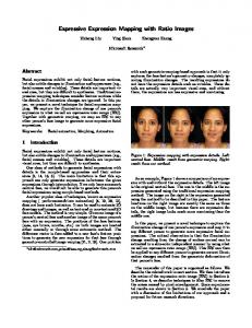
can show severe distortions. Therefore, in our application, the texture co-ordinates and scaling have to be computed accurately. 2.5 Surface Painting For each endoscopic view, we know the position, rotation and orientation of the endoscope tip in 3D. We place a modeled endoscopic “viewing cone” at the position of the endoscope tip, and extract the surface patch of the viewed object that falls with this cone (Figure 1 (a)). This surface is then intersected with 5 rays whose intersections correspond to the 3D positions to which the center and 4 equally-spaced points around edges of the texture patch are mapped (Figure 1(b)). Finally we calculate the texture coordinates of each polygon by tracing virtual rays from the vertex of each triangle, through the texture, to the localized endoscope tip (Figure 1 (c)) [19]. These co-ordinates are used to stretch and “pin” the 2D texture to the surface.
V
(a) Clipping
(b) Ray intersection
(c) Texture co-ordinate calculation (d) Merged
(e) Transparency effects
Figure 1. Our texture mapping method. (a) The endoscope tip is localized in the preoperative image and the surface patch is extracted by clipping. (b) The surface is intersected by 5 rays corresponding to the center and the 4 edges of the texture map. (c) Texture co-ordinates for each polygon are calculated by tracing virtual rays from each vertex V of each polygon to the localized endoscope tip. (d) The texture co-ordinates are used to “pin” the texture to the surface.(e) The transparency of darker pixels can be adjusted so that they do not occlude the surface.
As the endoscope sweeps across the object surface, cutout patches corresponding to the intersection of the endoscopic viewing cone with the entire surface are extracted. The texture co-ordinates for the new endoscopic position are computed, and the endoscopic images are texture-mapped to this surface. For each pose of the endoscope, a texturemapped cutout patch is added to the rendered scene. The surface patch corresponding to the most recent endoscopic pose is added last. This software is written primarily in C++, and the Python Programming Language, and is interfaced with the graphics toolkit The Visualization Toolkit (VTK) [16]. As the distance between the surface of an object and the endoscope tip increases, the light intensity decreases. In our application we have the option to transparently render the darker regions in the image (i.e. regions which have been insufficiently illuminated), so that they do not occlude the surface (Figure 1(e)).
3 Results 3.1 Visual assessment Figure 2(a) – (c) shows endoscopic images of the brain phantom. In Figure 2(d), these images are shown texture-mapped to the surface of the phantom. The views grabbed in Figures 2(a) and (b) are oblique projections of the 3D scene, as demonstrated by the lighting in the endoscopic image itself, and by texture mapped surface. In the endoscopic images, the light intensity decreases as the distance between the surface and the endoscope tip increases (Figure 2 (a) and (b)). Because the endoscope is tilted at an oblique angle to the surface, and the surface is not necessarily planar, the edges of the viewing cone clipping the surface are often jagged (Figure 1 (d), Figure 2(d)). All 2D views acquired by an endoscope are compressed into a circular field-of-view. However, from Figure 2 (d), it can be seen that when the endoscope is not oriented perpendicular to the surface, the circular endoscopic image is actually a compressed view of an ellipse in the case of an oblique flat surface, or a more complex geometrical shape for an arbitrary surface. The total number of virtual rays traced is equal to the number of vertices in the cutout surface (in this case less than 100 for each surface patch). In contrast, if we were to trace rays forward though every pixel in the 350x350 endoscopic texture, the number of virtual rays to be traced would be 122,500. One of the advantages of mapping the endoscopic images onto 3-D surfaces, is that even though the original images were monoscopic, the mapped images can be ascribed depth by the underlying 3-D structure, and visualized stereoscopically. Figure 2(d) shows such a stereoscopic rendering of endoscopic images texture mapped onto the surface it originated from. 3.2 Errors Our preliminary results demonstrate that the tracking accuracy of the POLARIS LED’s is 0.3 mm, and the endoscope tip can be localized with a precision of approximately 1.0 mm. We identified anatomical landmarks in both the pre-operative CT data and on the texture mapped surfaces. If we could localize the endoscope perfectly in 3D and there were no errors in our optical model, we would expect the position of these landmarks to
coincide in the two datasets, given that there is no tissue shift. We define the 3D distance between the original and texture-mapped locations of manually identified landmarks, as the texture mapping accuracy. For our phantom experiment, we found the average value of this measure to be 2.4 mm.
(a)
(b)
(c)
LEFT
RIGHT (d)
Figure 2. (a) –(c) Endoscopic images of brain phantom. (d) Stereoscopic rendering of the final 3D rendering (Cross-eyed stereo).
4 Discussion We have demonstrated preliminary results from a system that merges, in near real time, multiple tracked endoscopic views to 3D surfaces using a ray-traced texture-mapping approach. This allows both panoramic and stereoscopic visualization of the “painted” surface after the removal of the endoscope from the volume, as well as navigation within the volume. There are many improvements to be made to our methods for tip localization, and optical calibration, and our texture mapping algorithm. From our experience, before every endoscopic procedure, the endoscope must be optically calibrated, a procedure that must be rapid and reproducible, and be able to accommodate angled endoscopes. Further visual refinements could be made to the final 3D rendering with the mapped endoscopic images. In this work, our algorithm was applied to individual digitized video frames acquired with a tracked endoscope, but is in the process of being adapted to accommodate digitized streaming video. Our texture mapping error is an estimate of our overall error due to inaccuracies in optical tracking, registration of physical space to image space, and our optical calibration. However, we believe a more robust error assessment protocol is required since our current method is subject to errors associated with manual identification of landmarks. The validation experiments described here have been performed on phantoms, where the pre-operative image data accurately reflects the intra-operative state. In an actual endoscopy-assisted procedure however, we could expect additional small errors associated with brain shift. Currently the endoscopes used have been rigid, with their tip position extrapolated from the position of the tracking LED’s external to the body. However, tracking technologies exist that employ optical fibre properties, ShapeTapeTM , (Measurand Inc., Fredericton, Canada), and electromagnetic localization principles (Biosense Inc, Seatauket, NY) that could detect the position and orientation of the tip itself. This could enable the techniques described in this paper, to be employed with flexible endoscopes. Note that our surface painting algorithm is not limited solely to endoscopic images. It is equally applicable to mapping of video or still images of any object, acquired by any calibrated camera, to the arbitrary surfaces from which the original image emanated.
Acknowledgements We would like to thank our colleagues Dr. Yves Starreveld and Dr. Andrew Parrent for many useful discussions; Ms. Kathleen Surry for her help with endoscope calibration; Trudell Medical for the loan of endoscopic equipment, and Nuclear Diagnostics (Stockholm, Sweden) for the use of Multimodality software for segmentation. We acknowledge the financial support of the Medical Research Council of Canada, and the Institute for Robotics and Intelligent Systems.
5 References 1. 2. 3. 4. 5. 6. 7. 8. 9. 10. 11. 12. 13.
14. 15. 16. 17. 18. 19. 20.
Milgram, P., Kishino, F.: IEICE Transactions on Information Systems E77-D (1994). Grimson, W.E.L., Lozano-Perez, T., Wells, W.M. III, Ettinger, G.J.,White, S.J., Kikinis, R.: IEEE Transactions on Medical Imaging (1996). Konen, W., Scholz, M., Tombrock, S.: Computer Aided Surgery 3 (1998) 144-148. Jannin, P., Bouliou, A., Scarabin, J.M., Barillot, C., Luber, J.: SPIE Proceedings 3031 (1998) 518-526. Clarkson, M.J., Rueckert, D., King, A.P, Edwards, P.J., Hill, D.L.G., Hawkes, D.J.: Proceedings MICCAI (1999) 579-588. Szeliski, R., Shum ,H.Y.: Proceedings SIGGRAPH (1997) 251-258. QuickTime VR: http://www.apple.com/quicktime/ Surround Video: http://www.bdiamond.com Berci, G. (ed): Endoscopy. Appleton-Century_Crofts (1976). Perneczky, A., Fries, G.: Neurosurgery 42 (1998) 219-224. Perneczky, A., Fries, G.: Neurosurgery 42 1998) 226-231. Auer, L.M., Auer, D.P: Neurosurgery 43 (1998) 529-548. Jolesz, F.A.,. Lorensen, W.E, Shimoto, H., Atsumi, H., Nakajima, S., Kavanaugh, P., Saiviroonporn, P., Seltzer, S.E., Silverman, S.G., Philips, M., Kikinis, R.: AJR 169 (1997) 1229-1235. Foley, J., van Dam, A., Feiner, S., Hughs, J.: Computer Graphics. 2nd Edition (1990) Addison Wesley. Stefansic, J.D., Herline, A.J., Chapman, W.C., Galloway, R.L.: SPIE Conference on Image Display Proceedings 3335 (1998) 208-129. Schroeder, W., Martin, K., Lorensen, B.: The Visualization Toolkit: An ObjectOriented Approach To 3D Graphics. 2nd Edition Prentice Hall (1997). Tsai, R.Y.: IEEE Journal of Robotics and Automation RA-3 (4) (1987) 323-345. Haneishi, H., Yagihashi, Y., Miyake, Y.: IEEE Transactions on Medical Imaging 14 (1995) 548-555. Dey, D., Gobbi, D. G., Surry, K. J.M., Slomka, P. J., Peters, T.M.: SPIE Conference on Image Display Proceedings (2000) (in press). Haeberli, P., Segal, M.: http://www.sgi.com/grafica/texmap/index.html (1993).