Comput Mech (2008) 42:485–510 DOI 10.1007/s00466-008-0267-1
ORIGINAL PAPER
Materials integrity in microsystems: a framework for a petascale predictive-science-based multiscale modeling and simulation system Albert C. To · Wing Kam Liu · Gregory B. Olson · Ted Belytschko · Wei Chen · Mark S. Shephard · Yip-Wah Chung · Roger Ghanem · Peter W. Voorhees · David N. Seidman · Chris Wolverton · J. S. Chen · Brian Moran · Arthur J. Freeman · Rong Tian · Xiaojuan Luo · Eric Lautenschlager · A. Dorian Challoner
Received: 11 December 2007 / Accepted: 25 January 2008 / Published online: 2 April 2008 © Springer-Verlag 2008
Abstract Microsystems have become an integral part of our lives and can be found in homeland security, medical science, aerospace applications and beyond. Many critical microsystem applications are in harsh environments, in which longterm reliability needs to be guaranteed and repair is not feasible. For example, gyroscope microsystems on satellites need to function for over 20 years under severe radiation, therA. C. To (B) · W. K. Liu · T. Belytschko · W. Chen · B. Moran · R. Tian Department of Mechanical Engineering, Northwestern University, Evanston, IL, USA e-mail:
[email protected] G. B. Olson · Y.-W. Chung · P. W. Voorhees · D. N. Seidman · C. Wolverton · A. J. Freeman Department of Materials Science and Engineering, Northwestern University, Evanston, IL, USA M. S. Shephard · X. Luo Scientific Computation and Research Center, Rensselaer Polytechnic Institute, Troy, NY, USA R. Ghanem Department of Aerospace and Mechanical Engineering, University of Southern California, Los Angeles, CA, USA J. S. Chen Department of Civil and Environmental Engineering, University of California at Los Angeles, Westwood, CA, USA A. J. Freeman Department of Physics, Northwestern University, Evanston, IL, USA E. Lautenschlager Honeywell Aerospace, Plymouth, MN, USA A. D. Challoner Boeing Satellite Design Center, Los Angeles, CA, USA
mal cycling, and shock loading. Hence a predictive-sciencebased, verified and validated computational models and algorithms to predict the performance and materials integrity of microsystems in these situations is needed. Confidence in these predictions is improved by quantifying uncertainties and approximation errors. With no full system testing and limited sub-system testings, petascale computing is certainly necessary to span both time and space scales and to reduce the uncertainty in the prediction of long-term reliability. This paper presents the necessary steps to develop predictive-science-based multiscale modeling and simulation system. The development of this system will be focused on the prediction of the long-term performance of a gyroscope microsystem. The environmental effects to be considered include radiation, thermo-mechanical cycling and shock. Since there will be many material performance issues, attention is restricted to creep resulting from thermal aging and radiation-enhanced mass diffusion, material instability due to radiation and thermo-mechanical cycling and damage and fracture due to shock. To meet these challenges, we aim to develop an integrated multiscale software analysis system that spans the length scales from the atomistic scale to the scale of the device. The proposed software system will include molecular mechanics, phase field evolution, micromechanics and continuum mechanics software, and the state-of-the-art model identification strategies where atomistic properties are calibrated by quantum calculations. We aim to predict the long-term (in excess of 20 years) integrity of the resonator, electrode base, multilayer metallic bonding pads, and vacuum seals in a prescribed mission. Although multiscale simulations are efficient in the sense that they focus the most computationally intensive models and methods on only the portions of the space–time domain needed, the execution of the multiscale simulations associated with evaluating materials and device integrity for aerospace
123
486
microsystems will require the application of petascale computing. A component-based software strategy will be used in the development of our massively parallel multiscale simulation system. This approach will allow us to take full advantage of existing single scale modeling components. An extensive, pervasive thrust in the software system development is verification, validation, and uncertainty quantification (UQ). Each component and the integrated software system need to be carefully verified. An UQ methodology that determines the quality of predictive information available from experimental measurements and packages the information in a form suitable for UQ at various scales needs to be developed. Experiments to validate the model at the nanoscale, microscale, and macroscale are proposed. The development of a petascale predictive-science-based multiscale modeling and simulation system will advance the field of predictive multiscale science so that it can be used to reliably analyze problems of unprecedented complexity, where limited testing resources can be adequately replaced by petascale computational power, advanced verification, validation, and UQ methodologies. Keywords Multiscale modeling · Petascale computing · Microsystems · MEMS
Contents 1 Introduction and overview . . . . . . . . . . . . . . 486 1.1 Importance of microsystems . . . . . . . . . . 486 1.2 The need for petascale predictive-science-based multiscale modeling and simulation system . . 487 1.3 Outline of multidisciplinary predictive-science and simulation framework . . . . . . . . . . . . 487 1.4 The overarching problem . . . . . . . . . . . . 488 1.5 Overview of V&V UQ . . . . . . . . . . . . . 489 1.6 Overview of petascale computing . . . . . . . . 491 2 Multidisciplinary science and multiscale modeling of gyro-microsystem . . . . . . . . . . . . . . . . . 491 2.1 Materials stability and microstructure evolution 492 2.1.1 Thermal aging . . . . . . . . . . . . . . 492 2.1.2 Multiscale modeling of microstructure evolution . . . . . . . . . . . . . . . . . . . 492 2.1.3 Interdiffusion in metal layers . . . . . . . 493 2.1.4 Creep and grain boundary diffusion in Au bonding pads . . . . . . . . . . . . . . . 493 2.1.5 Phase field models for microstructural evolution and coble creep . . . . . . . . . . 493 2.1.6 Physics and modeling of radiation effects on microstructure . . . . . . . . . . . . . 494 2.2 Probabilistic models for constitutive behavior and materials damage and fracture . . . . . . . 494
123
Comput Mech (2008) 42:485–510
2.2.1 Linking microstructure and properties through predictive statistical multiresolution continuum constitutive and governing equations . . . 494 2.2.2 A statistical multiresolution approach to predicting material damage, degradation and failure . . . . . . . . . . . . . . . . . 495 2.2.3 An illustration of UQ in multiresolution constitutive relations . . . . . . . . . . . 495 3 Validation experiments . . . . . . . . . . . . . . . . 496 3.1 Overview . . . . . . . . . . . . . . . . . . . . 496 3.2 Microstructure evolution with Laser-Assisted LocalElectrode Atom-Probe (LEAP), X-ray scattering, and nano-tomography . . . . . . . . . . . 498 3.3 Creep experiment . . . . . . . . . . . . . . . . 498 3.4 Constitutive behavior . . . . . . . . . . . . . . 498 3.5 Shock load testing . . . . . . . . . . . . . . . . 498 4 Verification, validation, and uncertainty quantification (V&V And UQ) . . . . . . . . . . . . . . . . . 499 4.1 V&V and UQ methodology . . . . . . . . . . . 499 4.1.1 Verification methodology . . . . . . . . . 499 4.1.2 Validation methodology . . . . . . . . . 499 4.1.3 UQ methodology . . . . . . . . . . . . . 499 4.1.4 Optimal decision making under uncertainty500 4.2 An illustration of the proposed V&V and UQ strategy: multiscale modeling of creep . . . . . 500 5 Code components of the integrated software system 501 6 Integrated software system and petascale computing 502 6.1 Scalability and parallel performance . . . . . . 502 6.2 Implementation plan for multiscale simulation and uncertainty quantification . . . . . . . . . . 503 7 Novel microsystem materials design . . . . . . . . . 504 7.1 Actuation materials . . . . . . . . . . . . . . . 504 7.2 High Q coatings . . . . . . . . . . . . . . . . . 504 7.3 Anti-stiction coatings . . . . . . . . . . . . . . 504 8 Conclusions . . . . . . . . . . . . . . . . . . . . . 505 Appendix . . . . . . . . . . . . . . . . . . . . . . . . 505 Reference . . . . . . . . . . . . . . . . . . . . . . . . 508 1 Introduction and overview 1.1 Importance of microsystems Microsystems are devices that integrate mechanical elements, sensors, actuators, and electronics on a common substrate. Nowadays they have become an integral part of our lives— computers, cell phones, iPods, automobiles, aerospace systems, and biomedical systems all consist of these evershrinking microsystems. For example, a hard drive in a computer/cell phone/iPod is a micromachined cantilever system that reads and writes information. An accelerometer microsystem in a car is used to activate the airbag when a preset threshold acceleration is reached. A gyroscope microsystem in an aerospace system such as satellite and
Comput Mech (2008) 42:485–510
space station will be utilized for stabilization and navigation. Microfluidic devices are used to collect and analyze blood samples. The advances in microsystem technologies have brought and will continue to bring convenience to our daily lives (computers/cell phones/iPods), enhance health and safety (biomedical and automobile applications), and help to make major scientific discoveries (aerospace applications) among many other benefits. The market demand and application area of microsystems are expanding rapidly ranging from consumer electronics to industry, homeland security, medical science, aerospace applications and so on, making great synergy with the existing technology. The high frequency circuitry crucial for wireless communications will acquire considerable benefit from the radio frequency (RF) microsystems technology whose market is currently 1.2 million dollars in 2004 may grow up to 1.1 billion dollars in 2009 [1]. The market demand on microenergy sources such as micro-fuel cells and micro-turbine is also rapidly expanding with the application in consumer electronics and wireless sensor networks [2]. The mobile fuel cell market is expected to reach 1.6 billion dollars in 2010 [2]. Cell phones using microsystem technology have entered the marketplace in late 2003, and have already realized 56 million dollars turnover in 2005 and expect market growth up to 680 million dollars by 2010 [3]. The accelerometer and gyroscope microsystems start to serve in consumer electronic devices such as cell phones, game machines, and camcorders for orientation and stabilization. Micro-optical devices may have opportunities in display market with application like palm size projector. In 2004, the annual sales of microsystems have exceeded 5 billion dollars, and an annual growth rate of more than 20% is expected in the rest of the decade [4]. From either the health, science, technology, and economic view points, these developments are of significant national importance and interest. 1.2 The need for petascale predictive-science-based multiscale modeling and simulation system Major hurdles remain in ensuring the long-term performance and reliability of microsystems in harsh environments. Microdevices such as those on satellites and automobiles are subjected to harsh environments that include the following sources of damage: mechanical shock, solar radiation (electromagnetic waves and particles), and extreme thermal cycling that result in creep and material instability. Thermal cycling in satellite orbit results in material degradation that can lead to mechanical/electrical failure such as cumulative damage and fracture, distortion due to creep, failure of seals and electrical failure due to material diffusion. Similar problems have plagued other satellites. The recent news of the failure of the missile defense system test may have been due to aging [5]. Also, recently one of the three fuel cells on
487
Atlantis malfunctioned and is thought to be related to aging issues [6]. Similar problems have plagued other space vehicles. Improving the design of aerospace microsystems poses a unique challenge in that direct testing is not feasible. In the design of terrestrial systems for moderate lifetimes, engineers can usually test a design for failure. This is not feasible for aerospace microsystems because the lifetimes are very long and the environments cannot readily be duplicated in a testing facility. In addition, the use of new technology such as new microsystem devices in aerospace systems is also slowed by the fact that the aerospace industry is very conservative because one cannot afford to make a mistake [7]. There is a great need for a petascale verified and validated predictive-science-based simulation system with uncertainty quantification (UQ) in order to design microsystems for long operation time with certain confidence. Rapid advances in nanotechnology, nanomaterials, and nanomechanics offer huge potentials in private industry, homeland security, and national defense [8]. An emphasis on nanoscale design of materials will make our manufacturing technologies and infrastructure more sustainable in terms of reduced energy usage and environmental pollution. They can also broaden our understanding in areas of materials design, product design and manufacturing, surface physics, medicine, and among many others. The proposed petascale multiscale predictive-science-based modeling represents a paradigm shift from empirical fitting of modeling parameters to a modeling strategy that is based on fundamental physical understanding. In many cases, the former often only works on a case-by-case and trial-and-error basis while the latter is more successful but requires much more effort in validation with carefully designed experiments that are simple yet contain the essential physics. Multiscale predictive-sciencebased modeling and simulation can help to design better and smaller micro- and nano-devices with respect to their size, speed, and long-term performance. 1.3 Outline of multidisciplinary predictive-science and simulation framework Our major aim is to achieve a paradigm shift from empirical approaches of microsystem design to one which is based on multi-scale predictive-science. While the former relies on tests on prototypes, the proposed approach can treat situations where full duration system level tests are not feasible. This change in paradigm will offer many benefits in the design and maintenance of satellite Microsystems, because it is neither possible nor practical to pretest new designs for the long lifetimes and the environmental conditions that are required. It is anticipated that these approaches will be applicable throughout science and engineering. Such problems may be prevented by utilizing our proposed
123
488
predictive-science system to perform better design with novel materials. The proposed approach is based on three pillars: 1. Multidisciplinary predictive-science (Sect. 2). The development and advancement of predictive theory and methodologies for materials damage and failure, material stability, aging, and radiation effects, culminating in constitutive models that can be used for prediction of the performance of microsystems in satellites. 2. Verification, validation, and uncertainty quantification (UQ) (Sects. 3, 4). A methodology that addresses the following challenges in validation, verification, and UQ (V&V, UQ): • V&V of methods for which only incomplete experimental information can be provided. • V&V by a limited numbers of experiments of synergistic factors such as aging and radiation. • V&V of methods that link large range of space and time scales. 3. Petascale computing (Sect. 5). The development of a petascale integrated computational system that spans the scales from quantum mechanics to continuum mechanics for prediction of system performance and reliability under harsh environments. Two specific micro-gyro systems are used in our overarching problem to demonstrate our approach for the prediction of failure modes and system reliability as described in the next section. 1.4 The overarching problem The overarching problem is the prediction of the performance of a micro-gyro in a mission environment that includes radiation, thermo-mechanical aging and shock. The resulting phenomena include creep resulting from thermal aging and radiation-enhanced mass diffusion, material instability due to radiation, thermo-mechanical cycling, and shock. The resulting materials and mechanical issues are microstructure and phase evolution and material damage and fracture. These are by no means all of the potential sources of failure in a microsystem, but are instead focused on the mechanical/material effects which can effectively be treated by multiscale analysis. The specific systems that have been selected for demonstration are the Boeing disc resonator gyroscope (DRG) (US Patents 7,040,163 and 7,063,714) and the Honeywell tuning fork gyroscope Microsystems (US Patents 6,426,538). Additional background information of the micro-gyros and their design criteria are given in the “Appendix”. The prediction of materials/mechanical integrity will entail modeling from the quantum scale to the macroscale of the following: radiation effects, phase evolution, material
123
Comput Mech (2008) 42:485–510
diffusion fracture and damage. In our proposed predictive system, a bottom-up approach will be used to obtain coarser scale properties (coarse-graining), and a top-down approach will be used to “zoom” into the spots where critical phenomena (i.e., damage nucleation) are likely to occur. We will introduce methods for quantifying the uncertainties in our predictions from uncertainties in the finer scale models. The prediction of the overarching problem by a multiscale model will require petaflop computing. The fundamental science issues which are relevant to our overarching focus problem are as follows: (1) Aging of materials. A representation of the Boeing micro-gyro, which is shown in Fig. 1, contains bonding pads and contacts which are critical to its performance and lifetime. Also crucial to current microsystems is the LCC vacuum seal integrity since it keeps the gyro at very low air damping. The LCC vacuum seal may be made of a gold-tin and the die bonds are often made of thermal compression gold bumps (see top-left panel of Fig. 1), which may fail under the combined effects of creep, interdiffusion due to internal stresses, shock loading, radiation, and thermal cycling. The multilayer metal bonding pads (see lower-right panel of Fig. 1), composed of titanium, platinum, and gold, and the Au wafer bond used to bond the silicon cap and the substrate (see top-right panel of Fig. 1), are also critical to the gyro performance. They are susceptible to thermal aging, creep, and thermo-mechanical cyclic instability. The interdiffusion and phase evolution of the materials in the bonding pads may weaken the material interfacial strength. In addition, cyclic instability is of great concern in the gyro disc, where stresses are particularly high such as at the corners of the spokes (see lower-left panel of Fig. 1). (2) Fabrication effects. Some of the factors that may lead to failure arise from the fabrication process. For example, the aforementioned multilayer bonding pad, gold wafer bond, and gold bumps (see Fig. 1) are formed under thermal compression. The lattice and thermal expansion coefficient mismatches between different material layers lead to residual stresses. On the other hand, the temperature and pressure at which the fabrication of the gold bumps is performed determines their grain size, which controls their creep behavior. (3) Shock damage and fracture. Shock loading of microsystems is unavoidable in launch and repositioning, and hence the ability to predict shock response is of great importance. In the Boeing micro-gyro, the shock loads may damage or fracture the central support and electrode bonding sites of the disc or the interleaved segments between the concentric rings of the disc as shown in the lower-left panel in Fig. 1. Furthermore, aging generally weakens the material interfaces and bonds in the device and may increase risk of delamination. (4) Radiation effects. Radiation exposure can degrade device performance, and ultimately lead to device failure.
Comput Mech (2008) 42:485–510
489
Kovar Lid
Die Bond (e.g. Gold Bump) • Atomic Migration Energies • Grain Boundary Diffusivity • Grain Boundary Evolution • Damage Under Thermal Cycling And Shock Loading • Radiation Damage
Au-Sn Vacuum Seal • Microstructure Evolution • Delamination And Damage Under Thermal Cycling And Shock Loading • Radiation Damage
Au Wafer Bond • Atomic Migration Energies • Grain Boundary Diffusivity • Grain Boundary Evolution • Delamination And Damage Under Thermal Cycling And Shock Loading • Radiation Damage
Sensor Die
Si (Cap)
Au (350 nm) Leaded Chip Carrier (LCC carrier)
Electrode Damage • Vibrating Disc/Substrate Hitting Electrodes Under High Loads • Shock Loading
Disc Damage • Cyclic Stability At Disc Corners • Shock Loading
Si (Substrate)
Gold wiring
Si oxide Layer (500 nm thick)
Si oxide Layer (500 nm thick)
Ti (10 nm) Pt (20 nm)
P-doped Si (Disc)
Gold wiring
Au (350 nm) Pt (20 nm) Ti (10 nm) SiO2 (500 nm)
Multilayer Bonding Pad • Interfacial Structure And Energy • Compound Formation And Nucleation At Interface • Material Interdiffusion • Bonding Layer Microstructural Evolution • Delamination Under Thermal Cycling And Shock Loading
Fig. 1 Fundamental science issues related to long-term micro-gyro performance and reliability in harsh environment to the following components: top-left panel LCC vacuum seal and die bonds used in typical LCC package MEMS, top-right panel Au seal of the sensor die,
bottom-left panel resonator disc and the electrodes, bottom-right panel multilayer bonding pad at the central support between the disc and the substrate. See “Appendix” for additional details of the fabrication and operation principle of the Boeing DRG
For example, energetic particles lead to void formation in the vacuum seal causing embrittlement of the materials and accelerated creep. Consequently, an irradiated vacuum seal is more likely to fail under thermal cycling. We will focus on developing predictive calculations for the Boeing gyro with an emphasis on predicting long-term vacuum seal integrity and performance of the multilayer bonding pad, the gold wafer bond, die bonds, and the disc. Aging under thermal cycling, radiation, and shock loads which occur during launching and repositioning of an aerospace system will be considered. Figure 2 shows a 107 element mesh for multiscale analysis of the Boeing gyro and the critical areas that are crucial to the performance of the gyro.
gram of verification, validation and UQ. Because of the multiscale nature of the proposed predictive capability, new developments will be needed in certain areas, but we believe we can build on the capabilities in DAKOTA, a software environment for terascale optimization and UQ (described in Sect. 4) to handle many of the algorithmic aspects of the verification, validation, and UQ. However, substantial adaptation and enhancements will be necessary to address multiscale validation (Fig. 3). The following are the major sources of error to be considered:
1.5 Overview of V&V UQ The central and all-encompassing thrust in the predictive computational system will be a thoroughly interwoven pro-
(1) Software coding errors, e.g., blunders and bugs of codes; (2) Numerical errors, e.g., round-off errors, equation discretization errors, truncations in sampling; (3) Modeling errors, e.g., inadequacies of the model, incomplete representation of physics at key scales,
123
490
Comput Mech (2008) 42:485–510
Fig. 2 A finite element mesh (107 elements) of the Boeing DRG. The critical areas that require detailed analysis are a the vacuum seal, b die bond, and c the corners of the disc
a c b
(a) Seal (b) Die Bond (c) Corners
simplification/approximation of physical laws, improper coupling of information between scales, inaccuracies in scale linking methods; (4) Experimental errors, e.g., measurement error, variability in specimens, discrepancies between experimental setups and those used in computer simulations; (5) Model parameter uncertainties, e.g., initial microstructure, boundary conditions, material constants, modeling of the environment. The error sources (1) and (2) will be controlled through code verification, with the methodologies described in Sect. 4.1. Assessment of sources of error (3) through (5) will be achieved through the iterative validation procedure that includes three key aspects: (I) quantification of the confidence in the computational model by comparing predicted responses with corresponding experimental behavior, (II) extrapolation of the computational model from its calibration regime to conditions corresponding to the intended use of the model, and (III) the estimated confidence in model predictions will be compared with the specified requirements, for the conditions of intended use. To provide predictions of system performance with quantified level of uncertainty, we will validate material component models and their couplings at various length and time scales, progressing from component single-physics models to system models that predict coupled-physics performance under complicated environmental conditions (e.g., radiation-enhanced creep under thermal cycling). Validation experiments that can be used to provide vital data to the V&V and UQ effort are described in Sect. 3.
123
Source of uncertainties
Uncertainty Quantification & Management
Confidence assessment
Software coding errors
Verification Numerical errors Modeling errors
Adaptive control of discretizationsand adaptive model selection
Prediction - interpolation -extrapolation
Experimental errors
Validation Model parameter uncertainties Unmodeledfailure paths
Fig. 3 Overview of information flow in the verification, validation and uncertainty quantification (UQ) of the predictive multicale system
Uncertainty quantification is essential to validation and model prediction, where all of the quantified uncertainties from sources (2) to (5) obtained from V&V are propagated through the model to obtain the uncertainty in the prediction of system performance. Methods for uncertainty representation (UR) and uncertainty propagation (UP) are proposed (see Sect. 4.1) to gage the accuracy with which information is represented, to quantify the value of additional information, and to allow efficient information exchange between adjacent scales. We will leverage our recent developments in probabilistic multiscale multiresolution mechanics (see Sect. 2.2.3) with innovative stochastic representations (see Sect. 4.1.3) of the predicted system performance to enable the efficient evaluation of stochastic sensitivities. This will provide us with a prioritization of uncertainty reduction tasks in additional experiments.
Comput Mech (2008) 42:485–510
491
Fig. 4 Interaction of fundamental sciences at different scales due to various environmental effects and their associated codes
Aerospace Microsystem
50-100nm nm scale Atomic composition At material interfaces Via LEAP Grains of Gold Bump
Full System Prediction
Environmental Effects
Au
DAKOTA (V&V UQ)
Component and SubSystem Validation and Calibration
Processing Aging Radiation ThermoMechanical Loads
QM
TAHOE (Phase Field)
Energetics
Diffusion Nano Structure Evolution
MD + KMC Point Defects Diffusivities
TAHOE (MICRO)
TAHOE (MACRO)
Voids, Defects Dislocations Microcracks
Interfaces Macrocracks ‘Hot’ spots
Shock Load Particle Radiation Damage
Void Induced Softening Cold spots
1.6 Overview of petascale computing The execution of the proposed multiscale simulations and the associated probabilistic measurements will require the application of petascale computing. The effective parallelization of these computations is complicated by the fact that multiple interacting models are computed. Further complications arise because some of the models will dynamically evolve during the simulation, thus altering the distribution of computational load and communication. As indicated in Sect. 6, a component-based software strategy will be used in the development of our massively parallel multiscale simulation system. This approach will allow us to take full advantage of existing single scale components including TAHOE, LAMMPS, DAKOTA. Initial efforts will focus on scaling a multiscale simulation to massively parallel petascale computers. This will be followed by efforts to scale complete adaptive multiscale simulations and to execute those simulations on petascale computers.
2 Multidisciplinary science and multiscale modeling of gyro-microsystem The environmental effects on the micro-gyro and how they will be treated are illustrated in Fig. 4. As can be seen, the required modeling spans the scales from electronic structure calculations to the macroscale continuum scale. Between them are molecular models, and coupled phase fieldmicromechanics models. Fig. 4 also lists the exiting software codes to be integrated, which is further described in Sect. 5.
Hot spots DRG Stress Concentration At Corners
The arrows in the figure indicate how information will be passed; this information flow is also critical in our V&V and uncertainty analysis. The codes to be used at each scale and the approximate scales involved are listed at the bottom of the figure; these codes and their integration are discussed in Sect. 5. The fundamental sciences of the relevant phenomena are discussed in more detail in the next section. The approach entails two distinct disciplines, the materials science and the mechanical sciences of thermo-mechanical response. In addition, since radiation damage to the material affects both the phase formation and the microstructural evolution, the computations obtained by analysis of radiation damage to the material will be linked to both models as shown. In the complete analysis of the overarching problem, the macromodels will be linked with micromechanical models at selected material points, which in turn will be linked to the phase field models. The phase field and micromechanics models will be informed by the KMC molecular model of the statistics of the voids caused by radiation. The micromechanical models will provide the macromodel with the stresses for a given state of deformation that the macromodel has passed at any step of the evolution in the macromodel; note that there are two forms of the linkage between the micromodel and macromodel: a one-way linkage and a two-way linkage. The one-way linkage will be employed in the preponderance of the model: it implies that the effects of radiation, microstructure evolution and randomness have been incorporated in a constitutive equation which can be evaluated directly in the macromodel. The two-way linkage indicates that a detailed model of the microstructure will be used to evaluate the stress. This
123
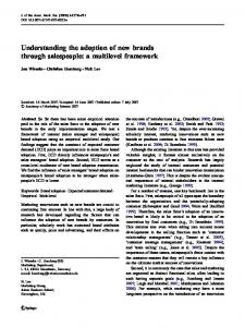
492 Fig. 5 First-principles MSCE calculated evolution of GP zones with Al–1.0at.%Cu at T = 373 K. Only Cu atoms are shown, and from the perspective view, it can be seen that precipitates form three variants of monolayer (100) plates consisting of pure Cu. Simulation times are shown in seconds [11]
Comput Mech (2008) 42:485–510
Solid Solution
t=0
linkage will be restricted to a selected set of points called “hot spots” at which critical response is expected. This will enable the computational system to predict the response at the macro-level for very complex microstates consisting of phase fields, microcracks, voids, dislocations, and grain boundaries. The evolution of these physical phenomena will be modeled at the micro-level in each unit cell without communication with adjacent unit cells, since the scale of these microstructures is quite small compared to the size of the unit cells and the interaction between microstructural entities in adjacent unit cells is expected to be small. This assumption will be validated by running concurrent analyses of smaller components in which a concurrent analysis is feasible. A phase field model will be directly linked to each microunit cell; the stress states will be passed to the phase fields since they play a critical role in the evolution of the phase fields. The stresses throughout the unit cell will be passed to the phase field model, driving the phase field evolution. The phase field morphology then determines the macroscopic mechanical properties through homogenization. As can be seen from Fig. 4, and in the more detailed description that follows, the phase field models are at the same length scale as the micro-model, but involve different physics. Aging in the micro-gyro is caused primarily as creep and phase changes in certain constituent materials, notably the Au–Sn vacuum seal, the die and wafer bonds, and the gold/ platinum/titanium/silicon layers between the disc and the substrate. These effects can be accelerated by radiation, so the results of the radiation computations will be linked to the phase field models as shown. Radiation also affects the mechanical response of the micro-gyro through the formation of voids, which alter the constitutive behavior. These will be reflected in the unit cells that will statistically model the voids and other defects in the material. Residual stresses from fabrication affect microstructure evolution significantly and will be obtained through experimental means. The response to shock is indirectly linked to the behavior at the smaller length scales. The time scales associated with shock are much shorter than the time scales associated with the evolution of phase field microstructure, so the shock response will be
123
Nucleation and Growth
t=8*106s
Coarsening
t=2.4*107s
t=1.6*108s
decoupled from the phase field and radiation damage phenomena, i.e., it will be assumed that these aspects of the microstructure are fixed within a shock computation. Therefore, the linkage in the shock computations will only be to the microstructural mechanical model; coupling to the phase field model will not be considered. 2.1 Materials stability and microstructure evolution 2.1.1 Thermal aging A thin multilayer is used to support the main portion of the gyro. It consists of nanometer scale layers of Au, Pt, Ti and Si (see Fig. 1). These components can interdiffuse over the long operating times of the device to form, for example, brittle compounds. Due to the interdiffusion process the interfaces between the layers can undergo morphological instabilities. Thus the diffusion barriers can be rendered useless. The gold bumps and the Au–Sn vacuum seal can creep by Coble creep under the residual stresses due to fabrication, which can alter the dimensional stability of the gyro and thus affect its accuracy. 2.1.2 Multiscale modeling of microstructure evolution The modeling approach of the aging phenomena is based on a combination of first-principles, kinetic Monte Carlo, and phase field methods [9–12]. First-principles electronic structure calculations based on density functional theory (DFT) will be used to compute detailed energetic information needed for coarser scale computations. In addition, vibrational entropies will be computed via the direct force-constant supercell method, producing free energies of idealized, perfectly-sharp interfaces as well as defect free energies. To enable the calculation of more realistic diffuse interfaces that will exist under thermal aging, we use the mixed space cluster expansion (MSCE) approach along with thermodynamic and kinetic Monte Carlo simulations (described below). Also, we will use this DFT energetic information to inform predictive phase-field calculations and the construction of modified embedded atom method (MEAM) potentials, also described
Comput Mech (2008) 42:485–510
below. The planewave methods Vienna Ab-Initio Simulation Package (VASP) and Full Potential Linearized Augmented Plane Wave Method (FLAPW) [13] will be used to obtain this energetic information. Specifically, we will use DFT to calculate aging-induced phenomena: (1) interdiffusion in metal layers and (2) creep and grain boundary (GB) diffusion in Au seal and bumps and Au–Sn vacuum seals. We show in Fig. 5 an example of this approach where a first-principle derived MSCE for Al–Cu is used with KMC simulations to predict the nanoscale evolution of Cu precipitates in Al, and a more detailed description of the MSCE is given in [11]. The results of the atomistic calculations for the diffusion coefficients, phase compositions, and process will be used as inputs to larger scale phase field simulations of the evolution of the multilayer pads and vacuum seals.
493
Fig. 6 Experimentally measured three-dimensional reconstruction of a solid–liquid mixture [16]
2.1.3 Interdiffusion in metal layers The MSCE is powerful, but constrained to the use of a lattice model. Thus, the problems that can be studied with this approach must contain a single, underlying lattice topology, and there must be a one-to-one connection between atoms and sites on this lattice (though, with the MSCE, the atoms do not need to sit precisely at the lattice sites). The metallic bonding layers of the micro-gyro provide an interesting and challenging assortment of material interfaces that will test the modeling tools, with some being applicable to the “single lattice topology” approaches (MSCE, LKMC, etc.) and others being specifically outside this domain of a single lattice type, and will rely on “off-lattice” simulation tools. Specifically, in the Au/Pt/Ti/Si interfaces, the Au/Pt interface is amenable to the MSCE and LKMC tools, as both metals are fcc. However, the Pt/Ti and Ti/Si interfaces cannot have a single underlying lattice topology, as Pt is fcc, Ti is hcp, and Si is diamond cubic. Hence, we will add to LAMMPS both the lattice and off-lattice tools. This will enable us to model the Au/Pt interfaces; we will compare and validate the results of each of the modeling tools. We will also include methods to model the Pt/Ti and Ti/Si interfaces using the off-lattice tools. The first-principles energetics will be used to construct accurate interatomic potentials, such as those based on the MEAM. These MEAM potentials currently exist for all of the pure elements of interest in this proposed work; however, the alloy potentials do not presently exist. We will use DFT along with the parameterization schemes of Baskes and co-workers (e.g., see [16]) to generate these alloy potentials. In addition, we note that the Pt–Ti system is well-known to form some of the most strongly bound intermetallic compounds of the entire transition metal series. Therefore, we will closely investigate the energetic competition and driving forces for interdiffusion vs. compound formation at the Pt/Ti interface.
2.1.4 Creep and grain boundary diffusion in Au bonding pads Grain boundary diffusion in Au will be modeled by first principle methods. We will use atomic models in LAMMPS with parameters as determined from experiments and quantum models [14]. Then we will use a combination of transitionstate finders (the nudged elastic band method, string method, etc.) to study various migration energies for Au along the GB, and compare this with the bulk diffusion energies. Largescale phonon calculations of these GB models will allow us to compute the prefactors for diffusion, entirely from firstprinciples. Wolverton and co-workers have recently used DFT total energy and phonon calculations to compute all quantities entering the self-diffusion constant in a bulk metallic system [15]. Both energies and entropies of vacancy formation as well as migration energies, and prefactors are computed completely from first-principles.
2.1.5 Phase field models for microstructural evolution and coble creep The phase field models will use technique on measuring the three-dimensional microstructure of materials in solid-oxide fuel cells and solidification structures developed by Voorhees [16]. They have shown that three-dimensional microstructures such as this can then be imported into a phase field calculation to determine the evolution of the structure (see Fig. 6). The seals will be modeled by a phase field method that allows for diffusion along the Si–An interfaces. This approach was used successfully in our work on the evolution of thin films by surface diffusion [17]. The diffusion coefficient for boundary diffusion will be determined from the atomistic scale simulations, as mentioned above.
123
494
The results of the atomistic calculations for the diffusion coefficients, phase compositions, and process will be used as inputs to phase field simulations of the evolution of the multilayer pads. These phase field simulations will also include stresses generated by lattice misfit, if we find that they are significant. The focus will be on two aspects of the evolution of the multilayer: the morphological evolution of the multilayer interfaces and the Coble creep of the gold bumps and seals. The morphological evolution accompanying phase formation will be treated by the phase field method. The stress induced evolution during Coble creep will be modeled in a manner similar to that mentioned above. The initial grain size and types will be determined experimentally. If the structure can be determined in three-dimensions it will be imported into the phase field code.
2.1.6 Physics and modeling of radiation effects on microstructure The vacuum seal is subjected to radiation in the space environment over life cycle of the microsystem. The interaction of radiation particles with a crystalline solid involves both electronic and elastic interactions [18]; the former involves electronic excitations while the latter results in the creation of Frenkel pairs. Considering only the effects of energetic ions, they tend to generate displacement cascades with dimensions that depend on the atomic number of the incident charged particle and the atomic number of the lattice. Displacement cascades consist of a core of vacancies surrounded by selfinterstitial atoms (SIAs) with high mobility at moderate temperatures. These defects can enhance diffusion and can lead to reduction in fracture toughness of the seal. The modeling of the displacement cascades will employ both molecular dynamics (MD) and Lattice Kinetic Monte Carlo (LKMC) techniques. MD simulations are currently limited to several nanoseconds, so the diffusive migration of the vacancies and SIAs for longer time scales cannot be treated. Thus, the long time temporal evolution of the primary state of radiation damage will be simulated by LKMC techniques. An LKMC simulation, when properly scaled, should yield the temporal evolution of the primary state of radiation damage in an elemental metal. MD simulations will be performed using the Sandia LAMMPS code (discussed in more details later) and augmented by a LKMC developed by Seidman. The LKMC code has been developed over the last 10 years and has been validated against known phase diagrams [9]. If it is determined that radiation damage enhances the bulk diffusion coefficient sufficiently, where the enhancement is a function of the flux, the energy and mass of the irradiating particle and the fluence, then we will include this mass transport process in the phase field model (see Sect. 2.1.5).
123
Comput Mech (2008) 42:485–510
2.2 Probabilistic models for constitutive behavior and materials damage and fracture 2.2.1 Linking microstructure and properties through predictive statistical multiresolution continuum constitutive and governing equations The thermodynamically derived BCJ internal state variable (ISV) model [19,20] developed at SNL will be used as a foundation to develop multi-physics multiscale constitutive models. The BCJ model relates the stress state to strain rate and provides a phenomenological model for phenomena such as dislocation hardening/recovery, grain growth, and damage evolution. Determination of the material parameters (constitutive model calibration) is performed from sub-scale models, based on Hill’s averaging theorems [21]. Parameters related to the effects of dislocation-void interactions and creep can be calibrated by comparing to phase field/micromechanics models and experimental results. Further micromechanics simulations will be used to develop evolution equations for the kinetics of grain growth and the effects of grain size on the constitutive response. The formation of cracks, shear bands and other dislocation-based effects should be predictable by a loss of rank-one stability in the associated continuum governing partial differential equations. Bazant and Belytschko have shown that the governing partial differential equations change type from elliptic to hyperbolic in such cases and the macroscale deformation localizes unphysically to a set of measure zero [22]. This can be accomplished by leveraging a multiresolution higher order continuum theory which builds on the pioneering work of Fleck and Hutchinson [23]. In this theory the gradient of the strain and a power conjugate couple stress are incorporated to include extra information about the inhomogeneous microscale response. We have extended this concept to multiple sub-scales or resolutions within the microstructure, and represent inhomogeneous deformation at each scale by a unique scale specific microstress and microstress couple. This is the first second gradient theory to capture inhomogeneous deformation at various length scales. Crucially, we are able to extend the Hill averaging theorem to compute the microstress constitutive relationships at each scale within a statistical unit cells of various levels of microstructures. Furthermore, to capture the random nature of the microstructure, a statistical character has been integrated into the multiresolution constitutive equations by utilizing an RVE ensemble, i.e., the multi-resolution averaging operations are performed over a large number of RVE microstructure configurations which represent a probability distribution of the actual microstructure. Both the stress and microstress constitutive relationships are then framed in terms of a
Comput Mech (2008) 42:485–510
set of scale specific probabilistic parameters, ultimately leading to a set of statistical multiresolution governing equations developed by Liu, Moran, Olson, and co-workers [5–7,24–28]. The ability to predict the changing scale of deformation, while incorporating the statistical properties of the microstructure, is crucial when performing macro-scale simulations. The multiresolution approach provides a variable length scale model, regularizing the post-instability strain at an evolving length scale which is consistent with the real evolving microstructure. The multiresolution predictive constitutive equations will be extended to model creep behavior. This is important for modeling the LCC vacuum seal, the multilayer bonding pads, and the Au bonds in the micro-gyros. Again, we will use the BCJ model [19,20] as a baseline for our macroscale creep model as it has a proven track record at Sandia in a wide variety of simulations involving the deformation of metals under both static and cyclic loading and temperature. Unit cell calculations can be used to pre-formulate the BCJ model for creep. We will consider two classes of unit cell models (i) unit cell phase field models (Sect. 2.1) and (ii) unit cell grain dynamics models developed by Chen [29– 33]. The roles of stress, temperature and radiation induced vacancies and GB diffusion (Coble creep) will be particularly important. The resulting BCJ constitutive model for gold will be used to model creep behavior in the LCC vacuum seal, the multilayer bonding pads, and the die and wafer bonds in the micro-gyro. First, device scale multiresolution mechanical simulations will be coupled with the continuum energy equation to accurately capture thermal effects on the mechanical behavior. This multiresolution thermal-mechanical simulation will then be coupled with a radiation enhanced mass diffusion equation. The resulting multiresolution thermalmechanical-mass diffusion coupled simulation will account for mass and temperature gradients, more accurately reflecting the interaction between diffusing damage (radiation induced vacancies), temperature, and irreversible plastic deformation. 2.2.2 A statistical multiresolution approach to predicting material damage, degradation and failure A multiresolution continuum theory has been developed to predict the failure of heterogeneous materials directly in terms of the microstructural evolution at multiple scales. Key aspects of the microstructural evolution, including damage nucleation, growth and coalescence, phase transformations and dislocation dynamics have been statistically parameterized in terms of the strain rate, thermal conditions, cyclic loading and stress triaxiality, via computational unit cell models. The resulting evolution equations have
495
been applied successfully within a multiresolution BCJ model [19,20] developed at DOE Trilabs. The outcome is a novel fracture simulator which predicts macroscale response from yielding to total loss of load carrying capacity, directly in terms of (i) the statistically parameterized evolving microstructure and (ii) the multiple scales at which inhomogeneous terminal damage is occurring. 2.2.3 An illustration of UQ in multiresolution constitutive relations Our proposed UQ process in multiresolution constitutive relations consists of three steps: (1) uncertainty quantification of inputs to the multiscale cell model such as random microstructure configurations and constituent material properties, (2) propagation of uncertainty from inputs to material constitutive relations (3) validation of the constitutive models via comparison with experimental data. Characterization of the stochastic microstructures at multiple scales will be carried out by examining multiple material specimens using the state-of-the-art methods such as TEM and X-ray diffraction. Based on microstructure images at various scales, microstructure features such as grain boundaries, particle distribution and defect locations will be measured and statistically characterized. The behavior of an ensemble of microstructures will be used to construct a random field representation of the response of the microstructure, which will enable the characterization of spatially heterogeneous properties. The computational expense associated with this feature will be mitigated through suitable stochastic reduced order models that permit an adaptive refinement of the stochastic resolution. Recently developed probabilistic representations that are uniquely adapted to the present multiscale analysis will be employed [34]. Specifically, multiscale stochastic processes that are indexed by scale (for either time or space) will be used. These will be mathematically represented as generalized stochastic processes [35,36] and will initially be described as a vector of random variables that simultaneously describe the random quantities of interest at all scales of interest: each component in that vector corresponds to a particular scale, and the components are correlated. Generalizing the random vector to a generalized stochastic process will enable the consistent exploration of a continuum of scales. To simplify the implementation, the assumption that the correlation matrix for this multiscale random vector is tridiagonal (indicating correlation is restricted to adjacent scales) will be employed, and this correlation will be obtained from a combination of computational methods and experimental observations used in a calibration procedure. This abstract model of randomness will further be represented for computational convenience using stochastic expansions that can
123
496
Comput Mech (2008) 42:485–510
Fig. 7 Uncertainty quantification of multiresolution constitutive relations based on stochastic microstructure characterization
S max 3.5
3 Configuration 3 Configuration samples samples
x 10
-8
*
3 2.5 2
16
x 10
1.5
8
1 0.5 0 1.2
14
1.3
1.5
1.4
S yield (Pa)
S max
12
3.5
Seq
10
x 10
1.6 9 x 10
-8
3 2.5
8
2 1.5
6
1 0.5
4
0 1.2
1.3
0
1.4
1.5
S max (Pa)
2
1.6 x 10
9
S softening 0
0.1
0.2
0.3 Eeq
0.4
0.5
0.6
3.5 x 10
-8
3 2.5
PDFofofstresses PDF stresses
2 1.5 1 0.5 0 1.2
1.3
1.4
1.5
S instab (Pa)
be readily sampled and analyzed, namely polynomial chaos (PC) decompositions. This multiscale stochastic representation is ideally suited to the concurrent multiscale approach as described in Sect. 2.2. In determining probabilistic microstructure–property– performance relations, it is essential to develop a UQ approach that can manage the complexity of using DNS for the entire macromodel. Strategies to “probabilistically” and “adaptively” identify the so called “hot spots” will be developed based on the stress concentration concept using kinematic variables such as strains (effective, stress, effective plastic strains resulting from statistical averaging), statistically averaged damage parameters, and strain hardening and recovery that can be obtained via dislocation dynamics. The more affordable multiresolution modeling approach (with material constitutive relations characterized by random variables) will be used for the most of the domain. As shown in Fig. 7, macro-scale constitutive relations (realized as stress–strain curves) can be parameterized by critical material property points located on those curves (e.g., yield stress and yield strain) that are themselves random variables whose joint probabilistic information can be inferred through computational synthesis. The computed macro-scale statistical constitutive relations can be validated against statistical experimental data obtained from experiments described next in Sect. 3.
123
1.6 x 10
9
3 Validation experiments 3.1 Overview The experimental component plays a key role in building confidence in our predictions. Experiments will be used to both calibrate and validate specific theoretical predictions. In some instance, it may be necessary to adjust experimental conditions to simulate long time scales, either because it is more practical to do so, or because the measuring instrument does not have the thermal and/or temporal stability over long time scales to produce experimental data with the required accuracy. Such experiments may be performed at higher stress or temperature, as long as the underlying physical phenomena responsible for materials or device degradation remain the same under these accelerated testing conditions. Testing samples will be subjected to degradation conditions (temperature, radiation and shock loading). These results will be used in model validation to progressively validate and refine the subcomponent computer models. Methodology developed under V&V and UQ will be used to design the physical experiments in a sequential manner based on the knowledge gained through experiments and the understanding of critical subcomponent models and the linking variables.
Comput Mech (2008) 42:485–510
497
Table 1 Validation experiment table Physics
Model(s)
Test samples
Experiment
Microstructure characterization
Input measure for V&V and UQ
Output measure for V&V and UQ
Component level experiments (each component is a specimen cut-out from the subsystem samples defined below in this table) Au/Sn seal, multilayer metallic bonding pads, shape memory alloys Polycrystalline gold, Au/Sn seal, single crystal silicon Polycrystalline gold
Atomic diffusion test
3D atom probe, small angle X-ray scattering
Temperature, initial composition profile
Composition profile
Proton and ion radiation
Energy spectrum, fluence, temperature Temperature, load, grain size distribution, grain aspect ratio
Void size distribution
Creep test
3D atom probe, small angle X-ray scattering Small angle X-ray scattering, X-ray tomography
Continuum with Polycrystalline gold, BCJ model/microscale multilayer metallic models (DD, bonding pads, GB)/nanoscale single crystal model (MD) silicon, shape memory alloys Sub-system level experiments
Static load and cyclic tests
X-ray tomography
Initial microstructure descriptor
Stress–strain curve
Performance tests under aging, radiation, shock loading, and cyclic loading
All of the above
Depends on the physics under consideration
Resonant frequency, fracture toughness, beam distortion, number of cycles to failure
Aging: material interdiffusion, phase formation (Sects. 2.1.3, 2.1.7) Radiation effects (Sects. 2.1.6)
continuum mass diffusion model/phase field model/KMC
Creep due to grain boundary diffusion (Sects. 2.1.4, 2.1.5, 2.2)
Continuum model/phase field model
Radiation defect evolution law/ MD+KMC
Grain aspect ratio,
Displacement time curve Constitutive behavior (Sect. 2.2)
Multiphysics (including all the above)
Sub-system model (low to high fidelity)
Cantilever beam, Au/Sn seal, micro-gyros with different conductive coatings
Table 2 Failure criteria table Failure mode
Failure mechanism
Components
Fundamental science
Failure criteria (Yi )
Seal leak
Creep, radiation damage
Vacuum seal
Creep/diffusion/radiation
Critical crack length > c
Fracture
Shock damage
Fracture stress > c
Distortion
Creep
Diffusion/radiation, crack nucleation/propagation Creep/diffusion/radiation Diffusion/radiation
Frequency shift > c
Novel material
Seizure
Frequency change
Property change
Vacuum seal, bonding pad, oscillatory parts Gold bump, multilayer bonding pad Oscillatory parts
Stiction
Surface interaction
Oscillatory parts
The various validation experiments to be performed at the component level and the subsystem level are summarized in Table 1. The component level tests are used to validate each separate physical process to be modeled as discussed in Sect. 2. The subsystem tests are used to validate the modeling of the coupling of multi-physics processes. The validated
Critical tilt > c
models will be used to predict the full system performance measures while a small amount of system tests will be used for confirmation. These performance measures include fracture toughness, overall distortion, and resonance frequency. For example, shock loading induces damages in the structure that alter the resonance frequency of its fundamental mode.
123
498
Creep and thermal aging in the multilayer metal bonding pad lead to distortion of the structure and fracture toughness degradation. The distortion can be measured by the degrees bent from the central axis parallel to the stem. Thermal aging and radiation also lowers the fracture toughness of the Au–Sn vacuum seal. Table 2 shows a list of failure criteria. The data required for the V&V and UQ are associated with both the inputs and outputs of a specific model of interest. The range of inputs of each component model will first be identified based on the intended use (see definition in Sect. 1.4). Uncertainty of each data source will be quantified and the worth of additional information needs to be studied (see methods in Sect. 4.1). The output data will be associated with the key performances that are observed in experiments and predicted by a simulation. These responses of interest will be chosen carefully to ensure that the UQ of a component model response will directly benefit the prediction of a system performance. All the characterization tools to use in these validation experiments (discussed below) are very accurate. All proposed experiments will be performed on multiple samples to ensure good statistics. 3.2 Microstructure evolution with Laser-Assisted Local-Electrode Atom-Probe (LEAP), X-ray scattering, and nano-tomography Validation of various models at different spatial resolutions discussed in Sect. 2 naturally demands different microstructure characterization techniques to be used to balance accuracy and efficiency. This is because sample size of an experiment scales directly with experiment resolution, for a given amount of time. To span various length scales, various microstructure techniques will be employed that include the Laser-Assisted Local-Electrode Atom-Probe (LEAP® ) tomography, X-ray scattering, and nano-tomography [37,38]. LEAP® tomography involves the atom-by-atom dissection of a small volume of a material. A typical laser-assisted LEAP® tomography run is now in the range of ca. 5 × 10⁶ to 3 × 10⁸ TOFs from which one can reconstruct the diffusion profiles with atomic scale resolution. For larger microstructural features such as micro-voids and grains, it is more appropriate to use X-ray techniques. Small-angle X-ray scattering provides direct information of the size distribution of micro-voids, while computer-aided X-ray tomography (CAT) provides 3D images of the microstructure. The combined use of these techniques will allow us to obtain the necessary resolution as well as good statistics to validate various models. For example, Fig. 8 shows an SEM image of the microstructure (grains) of the gold seal in the Boeing gyro. Figure 9 shows two SEM images of a gold bump of the Honeywell gyro that has been mechanically fractured. From these images, microstructure information such as grain size and shape can be extracted for validation purposes.
123
Comput Mech (2008) 42:485–510
Fig. 8 SEM image of a portion of Au seal belonging to a boeing microgyro system. The image clearly shows the grain shape and size (∼2 µm)
3.3 Creep experiment To calibrate and validate our combined phase-fieldmicromechanics models for creep behavior of gold bumps and other metals, thin film experiments can be performed. A sapphire punch will be loaded against a thick metallic film. The load will be chosen so stress is comparable to that in the micro-gyroscope. At constant load, the metallic film will undergo an initial deformation that increases with time. This creep is mostly due to GB diffusion and dislocation climb in the presence of vacancies. By measuring the creep rate as a function of temperature, the errors in the combination phase field models unit cells can be quantified. We can deduce the activation energy for this process. This information allows us to perform accelerated tests and validation of simulation prediction over long time scales (with and without irradiation), as discussed earlier. 3.4 Constitutive behavior Experiments will be performed with components consisting of thin multilayer microspecimens. The multilayer specimens will be subjected to long time static and cyclic loads and to shock loads. The results of these tests will be used to further calibrate the phase field/microscale models and to validate the integrated system. 3.5 Shock load testing The objective of the shock load testing is to determine the failure g-load for a given multilayer structure. The experiment involves directing a picosecond laser pulse towards the backside of the test sample. This results in the generation of a well-defined shock wave. The g-load can be calibrated as a function of the pulse energy (at fixed pulse duration) using a piezoelectric sensor. The critical g-load is determined from the threshold laser energy that induces failure of the structure,
Comput Mech (2008) 42:485–510
499
Fig. 9 SEM images of a gold bump within a Honeywell micro-gyro system. a The entire gold bump after it has been mechanically fractured. b The fracture surface showing ductile failure characteristics
as noted from cracking of the substrate or coating delamination. These experiments will be performed on multiple samples to obtain a meaningful Weibull plot to assess the statistical variation of the failure g-load. 4 Verification, validation, and uncertainty quantification (V&V And UQ) 4.1 V&V and UQ methodology 4.1.1 Verification methodology The starting point in our verification process for existing codes will be a thorough review of the previous verification activities for single codes. The code verification portion for assessing coding errors (source 1), will rely on benchmark solutions, to include analytical solutions and the development of manufactured solutions. The calculation verification portion for assessing numerical error (source 2) will rely on a posteriori error estimation techniques such as error estimators for finite element solutions by Zienkiewicz and Zhu [39] and Richardson Extrapolation [39,40] and possibly to estimate approximation and truncation errors. These methods will be carefully coordinated with adaptive methods for mesh discretization control [41,42]. For combined/coupled code calculation verification, it is suggested that new calculation verification methods, such as pointwise error estimation, be explored. In addition to the adaptive control of discretization errors, methods for the control of modeling and scale linking errors are under development. In those situations when there is a well qualified mathematical model hierarchy it is possible to effectively build off the methods developed for mesh discretization errors [43] to develop an adaptive control method. In other cases, methods based on physical hierarchy can be used [44]. 4.1.2 Validation methodology To address the three key aspects of model validation (see Sect. 1.4), we will use statistical model calibration [45] as
a core capability in our model validation methodology. This will help to construct probabilistic models that are quantifiably close to experimental evidence. The validation metrics [46] will wrap probabilistic measures around these physical quantities in order to enable the comparison of scatter in predictions with scatter in experimental evidence through statistical hypothesis testing. Of importance is the metric that can measure the global predictive capability of a model over a specified domain of interest as well as the metric for assessing the confidence of using the predictive model for an intended application. As an extension of model validation, the topic of model updating will be pursued. This will include bias correction, conditioning, and sensitivities with respect to experimental errors, sampling errors, and modeling errors [45,47–50]. A probabilistic procedure for multiscale validation will also be used to complement the above validation methods whereby the probabilistic scatter in the parameters estimated from a multiscale data assimilation procedure (Sect. 4.1.3) will serve as an indication of the confidence with which a particular upscaling procedure can be used. In addition, the probabilistic multiscale approach we propose permits an analysis of the error associated with the choice of a gradient-based theory in representing the mechanics. This can be easily achieved by computing, over an RVE, higher order gradients terms and estimating their influence on the performance metric. 4.1.3 UQ methodology Two distinct parts to UQ are considered in this work: UR and uncertainty propagation (UP). For UR, all sources of parametric uncertainty will be represented as stochastic fields indexed over space and/or time as appropriate. KarhunenLoeve expansions of stochastic processes can first be employed to deduce reduced-order representations in terms of a small denumerable set of random variables. These joint random variables can in turn be represented using their PC decomposition in order to capture their non-Gaussian character [45,51–53]. Using a single term in the Karhunen-Loeve expansion yields a representation in terms of the most
123
500
representative random variable, while including a single term in the PC decomposition yields a Gaussian model. Adaptive refinements can be pursued by monitoring the convergence of both of these expansions. We can rely both on asymptotic distributions and a posteriori distributions [45,54] for gaging the significance of additional measurements on the prediction confidence, as these measurements will reduce the variance of the sampling distribution. A suite of UP tools that implement stochastic projections (polynomial chaos), importance sampling, Latin hypercube, and Cubature sampling as well as combinations of these techniques can be employed. Many of these methods developed have been integrated into high-performance computing platforms, Sundance and DAKOTA at Sandia National Laboratory (SNL). The choice of UP method is problem dependent based on factors such as the statistical scatter in the parameters, and the scale of fluctuation of the solution in space and time. It is best to select the combination of these methods that is best suited to the initial output of the simulations. Efficient algorithms for uncertainty propagation need to be developed even with petascale computing. Algorithms that are both adapted to memory-bound or CPU-bound computations can be employed, thus providing options for integration into the petascale computational model as it evolves. These algorithms will essentially rely on conditioning by the mean model or an approximation thereof. Moreover, orders of magnitude efficiencies will be gained by relying on reduced order models to reduce the stochastic representation of our solution [54,55]. The UP and UR methods described above are ideally adapted to the present multiscale problem, in particular to the two issues of multiscale data assimilation and upscaling. Multiscale data assimilation. From a set of experimental observations at a coarse scale, the initial conditions for simulations at a finer scale will be computed as stochastic processes. This procedure can be applied for assimilation between any scale at which observations are available and the next finer scale. This can be carried out using two procedures: (1) Multiscale Ensemble Kalman filter procedure [56] and (2) Bayesian assimilation procedure [45]. These methods can be adapted to the probabilistic multiresolution continuum theory described in Sect. 2.2.3. Methods for stochastic upscaling will be used that permit the monitoring of the error incurred in this process. Advanced UP methods will be coupled with the multiresolution continuum theory to predict the failure of heterogeneous materials directly in terms of the microstructural evolution at multiple scales considering the random initial microstructure and other sources of uncertainties. Managing computational complexity of UQ. It is important to recognize the added computational burden that any UQ and V&V methodology will impose on a multiscale
123
Comput Mech (2008) 42:485–510
model-based prediction, and the wealth of opportunities to explore efficient algorithms on the UQ side of the computations. In order to keep pace with the flow of experimental measurements, we will use a mixture of models to represent uncertainties. Specifically, in the early stages, an interval model will be used to characterize those uncertainties obtained from an inverse analysis associated with experimental measurements (e.g., modal characteristics), while a probabilistic model with a non-parametric distribution will be used for the constitutive properties synthesized from subscale simulations. By treating interval variables as random variables whose distribution is an indicator function, we will be able to maintain consistency in the treatment of uncertainty across all aspects of the problem. For subsequent years, the output from the interval-based analysis will serve to construct a prior probability measure which will be used in conjunction with a Bayesian procedure to update the probabilistic models for both material parameters and experimental observations. 4.1.4 Optimal decision making under uncertainty It is important to prioritize validation and UQ tasks, and data collection activities. Our proposed UQ methodology facilitate for V&V by enabling the analysis of the effect of the various uncertainties based on statistical sensitivity analysis [57–59] and provide means to mitigate them. Finite resources in validation, including experimental data quantity and quality, schedule constraints, and computational limitations, make the design of validation procedure a very difficult optimization under uncertainty problem. The objective is to seek sequential physical and computer experiment designs [45,60] in terms of budgeted experimental resource (e.g., amounts of experimental data, cost of one single experiment) that maximize the utility function of a validation process considering various sources of uncertainties. The research here is to study how such utility function should be constructed to reflect the potential constraints on experiments and the value of improved model accuracy. Using optimal decision making, the obtained model errors with UQs can be used to determine the optimal combination of high and low-fidelity models in simulation. 4.2 An illustration of the proposed V&V and UQ strategy: multiscale modeling of creep Here we illustrate our V&V strategy for the creep model. The uncertainties associated with the modeling, simulation and validation experiments for creep are shown in Fig. 10. In the coupled DFT-KMC-phase field model, each model will be validated independently against existing experimental data, and then the coupled model will be validated against experiments conducted in this program.
Comput Mech (2008) 42:485–510 Fig. 10 Uncertainties in creep experiment and modeling
501 Uncertainties in experiment: Experiment setup variation; Measurement error; Sample variability Experiment
Input for Validation Temperature, loading (creep), initial microstructure descriptor
Atomic diffusion / creep experiment
3D atom probe/ X-ray Scattering/ tomography
Creep Simulation
Output for Validation Microstructure descriptor statistics (e.g., Grain aspect ratio) Displacement time curve (creep)
Phase field model
KMC DFT
or
Lower scale inputs from experiments
Uncertainties in simulation: Discretizationerror; Parameter uncertainty; Simulation domain size; Boundary Conditions; Uncertainty of initial microstructure representation
We can validate the accuracy of VASP by comparing against existing experimental data such as compound formation energies, diffusion constants, and phase diagrams. This can capture the physical modeling error (source 3 in Sect. 1.4); there are also approximation errors (source 2) associated with the choice of convergence criteria, energy cutoff, k-point sampling, which can be controlled and estimated through verification. The energetics in the off-lattice KMC method can be given by interatomic potentials fitted from many unit cell DFT calculations, which again introduces modeling error (source 3). Third, the particular form (source 3) of the phase field model is next formulated based on the phenomena observed in the KMC calculations. The parameters in the chosen model are fitted to the interfacial width and interdiffusion rates, for instance, from the KMC results. The validation of physical results generated from KMC and phase field model involves the same experimental measurements (i.e., interfacial structures and widths, rates of interdiffusion, and morphological evolution of the interfaces); however, the imaging needs to have the necessary resolutions to validate each because one is atomistic in resolution while the other is at nanoscale in resolution. In validating the multiscale (DFT + KMC + PF) model of Coble creep due to GB diffusion, we can compare two output measures of 1) the grain aspect ratio and 2) the displacement time curve for input measures of temperature, load, and initial microstructure. The variability in test samples can have a major effect on the result, and the scatter in creep experiment is about 1–5%. All proposed experiments will be performed on enough samples to ensure accurate statistics. Some of these experiments can be used to calibrate the diffusivities of grain boundaries, while the remaining experiments can be used to validate the predictions obtained through KMC and phase field simulations. The experimental observations can serve directly (without any inverse analysis) to construct a time-varying stochastic process model for the
diffusivities which can then be used in KMC simulations to propagate the corresponding uncertainty to phase field model input parameters. It can be assumed that the random diffusivities are statistically independent of the initial and boundary conditions at the atomic scale. These initial and boundary conditions can be assumed to be homogeneously random with very short correlation length, thus justifying the analysis over a typical (random set) of initial and boundary conditions.
5 Code components of the integrated software system The final multiscale integrated materials simulation system will consist of the software listed in Fig. 4. For example, we will build the petascale software system by linking several codes from the Tri-Labs and Northwestern University to Sandia’s TAHOE code, which will be linked to Sandia’s DAKOTA (a V&V and UQ code) and LAMMPS (an MD code) in the final simulation system after new capabilities for solving the overarching problem are added. A brief description of the various codes is given in the following. TAHOE is a research-oriented platform for the development of numerical methods and material models and was developed for the simulation of material response under conditions that cannot be treated by standard continuum simulation techniques. These situations include coupled-physics phenomena, fracture, and deformation in small-scale structures. LAMMPS is a molecular dynamics code that can model ensembles of particles in liquid, solid, or gaseous states. It is capable of simulating atomic systems using a variety of force fields and boundary conditions. LAMMPS runs efficiently on massively parallel computers, and can effectively model systems with up to billions of particles. LAMMPS has been benchmarked on ASCI Red, an Intel-based Tflop MPP
123
502
of about 9k processors, Red Storm, a Cray XT-3 with 10368 processors, and IBM Blue Gene/L to 64k processors providing promising scalability a peak of 4.34Tflop performance for a 40 billion atom calculation. Design analysis kit for optimization and terascale applications (DAKOTA) will provide the overall framework for the V&V and UQ activities of this project. DAKOTA contains algorithms for optimization; UQ with sampling/reliability/ stochastic finite element methods; parameter estimation with nonlinear least squares methods; sensitivity/variance analysis with design of experiments and parameter study capabilities; surrogate modeling, etc. As an open software toolkit, DAKOTA provides a flexible and extensible problem-solving environment as well as a platform for research of advanced solution methodologies.
6 Integrated software system and petascale computing The various computer codes will be integrated into an effective component-based system operating at the petascale. There will be three clusters of software: 1. TAHOE, the continuum code which will be used to model the micro and macro mechanics and the phase field evolution (the latter capability is to be added) 2. LAMMPS, the molecular dynamics code, which is to be augmented by the kinetic Monte Carlo method (KMC) 3. DAKOTA, the V&V and uncertainty quantification program We will employ a component-based software strategy in which functional interfaces support the interactions between procedures that are used to solve the individual models. We have extensive experience with this approach in high-level applications, such as the workflow modeling capabilities of the SciDAC Scientific Data Management Center for Enabling Technologies [61] and UQ capabilities of the DAKOTA toolkit [62], both will play an important role in this project. Component-based software architecture are also being used to develop the mesh-based simulation procedures in the ITAPS SciDAC center [63] and commercially by Simmetrix [64,65]. These efforts include the parallelization of the processes using MPI-based distribute memory methods in the development of parallel adaptive finite element codes [63,66]. Over the past several years we have been applying this approach in the development of multiscale simulation procedures. Building on an abstraction of the functional layers and information transformations and transfer between layers in multiscale simulations [67], component-based procedures have been constructed for both hierarchical [68] and concurrent [69] parallel adaptive procedures. LAMMPS is
123
Comput Mech (2008) 42:485–510
the MD component in the concurrent multiprocessor continuum/atomistic code developed [69]. This and similarly developed capability can be used to support the interactions between existing software components used in this project. 6.1 Scalability and parallel performance Many factors must be addressed in the development of a scalable adaptive multiscale simulation for 100,000+ processors. These include: • Ensuring that there are enough concurrent calculations in a given step (i.e., a given set of models and discretizations). • Implement sufficient control of the communications to achieve scalability. • Provide a set of structures and algorithms to provide adaptive control for a scalable execution of the multiscale simulation. • Dynamically load balance the calculations for the each step in a scalable manner. Based on the sizes of models described previously, the proposed simulations will require petascale computing. The first question to be addressed is whether the single scale analysis tools can scale to petascale. The LAMMPS molecular dynamics code has already shown acceptable performance on the LLNL Blue Gene/L system [70] and is expected to extend to the petascale machines for large enough atomistic systems. For continuum simulations we will build on TAHOE which has been parallelized using the Aztec [71] and SPOOLES [72] solvers and can be effectively integrated with other parallel solver technologies (e.g., PETSc [73] and Trilinos [74]). Efforts will be required to scale TAHOE to petascale class machines and to effectively support parallel adaptive methods. This effort will rely heavily on a combination of mesh partition and matrix free solution techniques. We have recently performed scaling tests of an RPI internal unstructured finite element code on IBM Blue Gene/L’s at IBM and Rensselaer. In one test on a 5 million vertex mesh, doubling the number of processors form 512 to 8,192 processors maintained a 95% scaling on the fixed mesh. A second test on an 18.5 million vertex problem showed a 99% scaling in going form 1,024 to 16,384 processors [66]. Those technologies will be brought into TAHOE. Central to the parallel multiscale analysis is controlling load distribution and interprocessor communications for the heterogeneous computations performed. Since it is desirable that the computations be adaptively executed, computational load balancing must be dynamically applied as the computation executes. Sandia’s Zoltan software [75,76], which supports load balancing of general objects with both computation and communication weights, represents a starting point for
Comput Mech (2008) 42:485–510
503
Fig. 11 Parallel adaptive mesh example (colors correspond to processors)
this need. We already have experience on the development of parallel adaptive simulations [63,66,77,78] (see example in Fig. 11), and have begun applying those methods to parallel adaptive multiscale analyses [68,69]. Among the extensions to current methods that are needed for parallel multiscale codes are multilevel dynamic load balancing. For example, we will need one level of dynamic load balancing to deal with the large set of unit cell models on the microscale and a second to deal with the adaptive control of the coarsest scale model.
6.2 Implementation plan for multiscale simulation and uncertainty quantification As indicated above, we will take extensive advantage of software and methods that have been developed by DOE and their university partners. In several cases, we will use this software without modification, in others we will work closely with the developers to perform extensions such that their tools can operate effectively as a component (e.g., the LAMMPS example above) or to add a needed feature. One code for which more extensive developments are needed is TAHOE which will be the central tool for the multiscale simulations. To gain an appreciation for the process of performing a terascale multiscale simulation and the types of capabilities to be integrated into TAHOE, we consider the shock loading of the disk of a micro-gyro. The next paragraph defines the problem and the paragraph after that considers it parallel solution on petascale computers. In the petascale simulation of the coupled macro–micro continuum model, the macro model will be discretized into an adaptively refined mesh of order 107 elements. In the hierarchical multiscale model, the microscale model is linked at selected points in the critical portions of the macro model. For the current discussion assume there are 5,000 such locations. Let’s further assume that at these locations the influence of nano voids is important. Thus the micro-model unit cell may have a mesh of 100,000 elements. (Note that when UQ and other statistical aspects are included, there will need to be more unit cells considered.) Assume the unit cells problems are solved using an explicit method and that 100 time
steps are needed on the microscale for each macroscale time step. The most obvious approach to the scaleable solution of this problem on a petascale parallel computer requires the ability to do an implicit solve on the macro mesh using the scalable solvers discussed above. In addition, the system (i.e., the mesh and equations) must be constructed in parallel. Since the formation of the system contributions for a macro-element with a microscale material point model may require the solution of 100 time steps of a 100,000 element mesh, it is not reasonable to use a single level load balancing process. In this case, a two level method would be suitable: elements that require material point model solves (i.e., hot spots) would be distributed over multiple processors while groups of standard macro elements are constructed on other processors. Algorithms that operate in parallel over distributed meshes will be developed to determine the workloads and to construct the appropriate communication graphs for parallel load balancing using instances of Zoltan [75]. Since these procedures must operate in parallel on distributed structures, they can be used to support adaptive processes where the workload distribution changes as simulations proceed. Note that the general methodology of constructing levels of parallel computations and distributing them can be applied to the other multiscale couplings of interest here, including concurrent methods, coupled atomistic-continuum models, time scale linking, various methods of adaptive model and discretization (mesh) control, etc. We plan to generalize the implementation of these approaches. Massively parallel computers that can deliver a sustained petaflop computation are estimated to have around 500,000 processing cores. Therefore it is critical to account for the fact that cores or nodes can fail during a multiscale simulation. A standard approach to deal with this is file-based check pointing for restarts. With this many processors, this is unlikely to be an effective approach. Since it is possible to recover one step in the simulation by the storage of a small fraction of the total data, a feasible strategy may be the following. Each processing node is paired with a neighboring node. These two nodes maintain a copy of the restart information for each other while maintaining
123
504
their own data. In addition, for a larger grouping of nodes, a few nodes are reserved to replace any node that is lost. In this model the system can continue to recover as long as both members of a node pair do not fail on the same step. Since much of the proposed UQ effort will evolve around DAKOTA, the parallelization task is simplified using DAKOTA’s advanced functionality for multilevel parallelism. We will use DAKOTA as a wrapper and function-callmanager, for carrying-out the stochastic projection approach [51] to UQ and propagation. This approach essentially entails computing the PC approximations to the solution using a stochastic Galerkin projection.
Comput Mech (2008) 42:485–510
vides an ideal opportunity to demonstrate the application of our full set of predictive-science tools spanning martensite kinetics, nanoscale precipitation, multiscale mechanical behavior, and probabilistic system integration, while incorporating previously well studied aging effects in shape memory alloy systems. Potentially, we can integrate our multiscale predictive-science tools in the accelerated reliable engineering of this new class of nanostructured high performance shape memory alloys for aerospace microsystems, exploiting validated predictive-science to accurately forecast their long-term evolution in service. 7.2 High Q coatings
7 Novel microsystem materials design Materials design activities which synergistically exploit the developing modeling capabilities of the parallel research thrusts will address enhanced materials stability for component reliability in both existing sensor and future actuation microsystems. In line with the longer-term nature of new material design, the examples will emphasize high power density microactuation materials of interest for stable operation in laser micromirror systems. 7.1 Actuation materials An important component of aerospace microsystems is the actuation materials that can enable reliable high power density mechanical devices. A potential high-impact example of the latter, of particular interest to Boeing, is the use of high displacement actuation materials for precise control of laser micromirror systems. Shape memory alloys activated by resistive heating have been identified as offering unique potential for desired high power density, particularly as the efficient heat transfer in thin-film form allows desired high frequency of operation. TiNi-based shape memory alloys have been proposed as particularly suitable for radiation environments. Current commercial shape memory alloys, however, suffer from limited cyclic life. This limitation has been addressed in the recent computational design of nanodispersion-strengthened shape memory alloys demonstrating greatly improved parent-phase strength to enable both higher output force and enhanced cyclic life through elimination of accommodation slip during martensitic transformation. Preliminary prototype alloy evaluation indicates that optimization of nanodispersion particle size can provide a predictable stored elastic energy effect on phase stability without increasing transformation hysteresis. The problem of detailed optimization of the particle dispersion interaction with martensitic transformation is well suited to our microstructural simulation tools. The productive integration of these novel materials into aerospace microsystems pro-
123
Application of predictive-science-based coating design will emphasize conductive coatings on high performance (high Q) quartz resonators for the navigation grade DRG microgyroscopes. The coating material designs will have more immediate impact through integration in the microgyroscope system development. High-precision micro-gyroscopes must have large Q-factors (= resonance frequency/width of the resonance). Finite Q-factors are due to various energy loss mechanisms, such as phonon dissipation, internal friction and electronic excitations. Previous experiments demonstrated that with the use of quartz in the micro-resonator, the primary energy loss is due to electronic excitation in the electrical contacts. Conceptual designs of conductive coating materials for the quartz resonators can explore both initial performance and the stability of the coating Q to environmental exposure including radiation. In addition to conventional candidate coating metals of Al, Pt, and Au, bismuth is also a strong candidate, because its room-temperature electron mobility is 600 times greater than that of gold. Potential stability against radiation induced defects can ultimately be validated by internal friction measurements after radiation exposure. 7.3 Anti-stiction coatings Stiction is a phenomenon that may occur in micro-systems with suspended structures. Failure occurs when the stiction force is strong enough to bring a key structure of the microsystem into contact with the substrate. When the adhesion force exceeds the elastic restoring force after the contact is established, the structure is pinned to the substrate. One solution to this problem is to coat both surfaces (structure of interest and the substrate) with a material that exhibits low adhesion in a normal air or vacuum environment. Conceptual design activities can explore a range of possible coating strategies to mitigate this failure mode, employing the developing atomistic modeling tools. One candidate material already identified is sulfur-doped diamond-like carbon (DLC). The mechanism proposed for theoretical evaluation
Comput Mech (2008) 42:485–510
is that a sulfur-doped DLC surface markedly slows down the rate of oxidation, thus maintaining a non-polar surface for extended periods; this in turn suppresses adsorption of water vapor from the ambient and thus capillary/adhesive forces due to the presence of adsorbed water. After model-based theoretical evaluation of such coating concepts, validation experiments can use atomic force microscopy (AFM) to measure the adhesion between a silicon tip of known geometry and a flat silicon surface, both coated with the prototype materials. After exposing the two surfaces to air with controlled humidity, their adhesion can be directly measured using the pull-off technique.
505
trast to the hemispherical shell design requiring cumbersome conventional machining. The disc consists of a number of circular concentric rings and interleaved segments connecting the concentric rings. A number of electrodes can be co-etched to protrude out from the substrate through the slots between the concentric rings of the disc, to sense or drive mechanical displacement. The disc generally has two in-plane vibration modes at resonance and the orientation of the vibration mode changes during rotation of the entire device according to the Coriolis effect. The disc and the electrodes are made of doped silicon in typical design, but fused quartz with a thin layer of conductive thin film can replace silicon as the disc material to obtain better performance as will be described in more depth below.
8 Conclusions A1.2 Operation principle of the DRG We have presented a roadmap for a petascale predictivescience-based verified and validated multiscale modeling and simulation system to predict the performance and materials integrity of microsystems. The development of the predictive system consists of integration of the following three thrusts: (1) the modeling of long-term materials instability, aging, and radiation-enhanced microstructure evolution by coupling quantum/atomistic-mechanical, phase field models, micromechanics, and multiscale statistical continuum mechanics models; (2) the development of verification, validation, and UQ methodologies and implementation of them on petascale platforms; and validation of computational models on microsystem components and subsystems including: vacuum seals, resonators and metallic bonding pads; (3) development of a petascale software system by a component-based integration approach. We emphasize that although our focus is on microsystem performance and reliability prediction, the roadmap should be applicable to developing similar predictive simulation software for other complex systems such as high strength alloys, energy harvesting systems, or even biological systems, with few modifications.
A1. The Boeing disc resonator gyroscope (DRG)
At resonant frequency (∼20 kHz), the disc resonator has two degenerate in-plane vibration modes so that the vibration pattern depends on the excitation direction. The disc is driven to resonance by the driving electrodes with AC voltage near the resonant frequency. The driving electrostatic forces depend on the sign and amplitude of the charges accumulated at the driving electrodes and the disc. To sense mechanical motion of the disc, capacitance sensing is used in that the sensing electrodes and the disc together act as a capacitor. Any change in the gap size between the sensing electrode and the disc results in a change of electric current in the integrated circuit. The vibration pattern of the gyroscope changes upon rotation of the entire microsystem according to the Coriolis effect as shown in Fig. A2. In addition to the centrifugal force acting on the disc during rotation, an additional acceleration called the Coriolis acceleration acts on the disc if the disc is already in vibratory motion before the rotation. The Coriolis acceleration dominates the centrifugal acceleration for this device, and it is given by a = −2ω × v where ω is the rotation vector and v is the velocity of a point on the disc. Since the velocity at every point on the disc is different, the Coriolis acceleration forces the vibration pattern to change. Therefore, the vibration pattern change can be correlated to the gyro rotation rate in order to determine the latter in real applications.
A1.1 Description of the Boeing DRG
A1.3 Fabrication of the DRG
The Boeing Disc Resonator Gyroscope (DRG) (US Patents 7,040,163 and 7,063,714), exemplary representation of an aerospace micro-gyro system in our focus problem, is a discshaped resonator supported on a central silicon stem that is bonded to a silicon substrate (see Fig. A1). The planar disc design allows modern micromachining techniques to be used to manufacture this standingwave gyroscope device, in con-
The micro-gyroscope is made by micromachining two singlecrystal silicon wafers, one for the disc and one for the substrate with gold wires deposited on it, which are subsequently bonded together (Fig. A3). A 500 µm thick doped silicon wafer is used for the disc. Multilayer bonding pads are deposited at the electrode and center support sites in the following order: a 10 nm thick titanium (Ti) layer, a 20 nm thick
Appendix
123
506
Comput Mech (2008) 42:485–510
Fig. A1 The Boeing disc resonator gyroscope (DRG). a A photo showing the top view of the disc on a substrate. b A schematic assembly drawing of the sensor die
(a)
(b) Silicon Cap
Electronic Control Unit Resonator Disc • P-doped Si or metal coated fused quartz
Silicon Oxide Layer • Gold Wiring on Top
Sensing and Driving Electrodes • P-doped Si
Au seal Multilayer Bonding Pads at Central Support
Silicon substrate
36º
Standing wave vibration pattern: aftercase rotation
1. Begin with a piece of single crystal silicon (500 micron thick)
Substrate 2. Etch out desired pattern of center support and electrodes
90ºcase
rotation
5. Begin with another piece of doped crystal silicon (500 micron thick)
Substrate
Disc 6. Etch out the desired pattern and lay down the bonding pads, each of which consists of a layer of titanium (10 nm), a layer of platinum (20 nm), and a layer of gold (350 nm)
3. Oxidation to obtain a layer of silicon oxide (150 nm)
Substrate
Standing wave vibration pattern: beforecase rotation
4. Lay down the bonding pads, each of which consists of a layer of titanium (10 nm), a layer of platinum (20 nm), and a layer of gold (350 nm).
Substrate
Disc 7. Bond substrate piece and disc piece together.
Disc Substrate 8. Etch out slots on the disc and electrodes on the subtrate
Disc Substrate
Fig. A2 Vibration pattern of the Boeing DRG Fig. A3 Fabrication process of the Boeing DRG
B1. The Honeywell tuning fork gyroscope platinum (Pt) layer, and a 350 nm thick gold (Au) layer. On the other hand, the fabrication process of the Substrate starts with a 500 µm thick doped silicon wafer. The silicon wafer is first etched to produce the desired pattern for the center support and the electrodes and then the top surface is oxidized to produce a 150 nm thick silicon oxide layer that serves as electrical isolation from the doped silicon below. The bonding pads of identical composition as described above are deposited on top of the oxide layer at the electrode and center support sites, which are connected by gold wires that are deposited subsequently on top of the substrate to vertical interconnect pins on the perimeter to a third, end cap wafer with VLSI gyro control electronics and the gyro external electrical connection pads. The disc and substrate wafers are bonded together at the electrode and center support sites by applying pressure and heat at approximately 400◦ C to form single-bonded metal joints. Finally, the slots with or without the electrodes inside the slots are formed from the bonded structure through etching.
123
B1.1 Description of the Honeywell tuning fork gyroscope The Honeywell Tuning Fork Gyroscope consists of a p-doped silicon structure that is attached to a lower glass substrate with gold layering deposited on it, as represented by the generic tuning fork design in Fig. B1. The silicon structure consists of two proof masses supported by a pair of trusses that are anchored to the glass substrate. During operation of the gyro, the proof masses are driven electrostatically at the comb teeth edge by an outer motor drive and vibrate in-plane and antiphase to each other. If a rotation is applied about the horizontal axis perpendicular to the velocity vector of the masses, one proof mass would rise and the other would sink due to the Coriolis Effect, as schematically illustrated in Fig. B2. The motion of each proof mass is sensed by a capacitor, which is made from the bottom side of the proof mass, and a gold layer deposited onto the associated glass substrate below the proof mass.
Comput Mech (2008) 42:485–510
507
Fig. B1 Tuning fork gyroscope. a Entire device with proof masses on either side of the central axis. b The comb teeth between proof masses and the central axis
1.
Highly doped epitaxial silicon is grown on top of lightly doped silicon substrate.
4. Bond silicon and bottom glass substrate and Doped silicon substrate
Lightly p-doped Highly p-doped
2. DRIE (Deep Reactive Ion Etching) etch to define silicon pattern
Glass substrate
5. Etch away all the lightly doped silicon, leaving the patterned highly doped epitaxial silicon layer proof mass
proof mass
Glass substrate
3. Pattern and etch the bottom glass substrate. Deposit gold layering Gold capacitor plate Glass substrate
Fig. B3 Fabrication process of the Honeywell gyro
Fig. B2 Operating principle of the Tuning Fork Gyro similar to Honeywell design. It is based on the Coriolis acceleration, a = −2ω × v where ω is the rotation vector and v is the velocity of a material point on the proof mass. a Top view, b front view
B1.2 Fabrication of the Honeywell tuning fork gyroscope The sensor is manufactured by the process as shown in Fig. B3. First, highly p-doped epi silicon is CVD grown on top of a lightly p-doped substrate. In the final sensor structure, all the lightly doped portions are etched away. On the other hand, the glass substrate is micro-machined separately, then bonded to the silicon. A mesa channel, which forms the sense gap underneath the proofmass, as well as interconnect patterns are etched and deposited onto the glass substrate. The final patterned glass substrate is anodically bonded to the silicon substrate by applying a combination of heat, pressure, and electrostatic field to form strong chemical bonds
between silicon atoms of the wafer and oxygen atoms in the glass. As shown in Fig. B3, starting with a lightly p-doped silicon substrate, a highly p-doped epitaxial silicon layer is grown on the substrate. A layer of photosensitive film is deposited on top of the highly p-doped silicon layer, which is then patterned with a mask with the desired features. The silicon substrate is then exposed. Deep Reactive Ion Etching (DRIE) is used to etch the silicon pattern on the highly p-doped silicon layer, such as the mechanical, electromechancial members of the device and proof masses. Finally, the remaining portion of the photosensitive film is removed to give the final pattern of highly p-doped silicon layer on lightly p-doped silicon substrate. On the other hand, a glass substrate is used as a bottom support. First, the substrate is etched to have the desired pattern. A photosensitive film is placed on the surface of the glass substrate and then is partially covered by mask with the desired pattern for the features. Exposing it in the light, the photosensitive layer is then removed with the developer solution. The portion of the support substrate that is not covered by the mask is etched till the mesas are formed with the desired height. Then another layer of photosensitive film is placed on top of each substrate and is then covered with another mask with the desired metallization pattern. Exposing the support substrate in the light again and etching the portion without
123
508
Comput Mech (2008) 42:485–510
Table C1 Performance requirements for different classes of gyroscopes [79]
References
Parameter
1. RF MEMS market 2004–2009 by Wicht Techonologie Consulting, October 2005 2. Micro power sources: opportunities from fuel cells and batteries for mobile applications by NanoMarkets. http://www.nanomarkets. net, September 2005 3. MEMS microphones and micro-speakers market. Workshop by Wicht Technologie Consulting (2006) 4. Microelectromechanical Systems Technology: Current and Future Markets by Andrew McWilliams, February 2006 5. Chicago Tribune on July 6, 2006 6. abcnews.com on September 6, 2006 7. Mechanical Engineering, April 2006 8. Liu WK, Karpov EG, Park HS (2005) Nano-mechanics and materials: theory, multiscale methods and applications. Wiley, New York 9. Mao Z, Sudbrack CK, Yoon KE, Martin G, Seidman DN (2007) The mechanism of morphogenesis in a phase separating concentrated multi-component alloy. Nat Mater 6:210–216 10. Vaithynanathan V, Wolverton C, Chen LQ (2002) Multiscale modeling of precipitate microstructure evolution. Phys Rev Lett 88:125503 11. Wolverton C, Zunger A (1995) Ising-like description of structurally relaxed ordered and disordered alloys. Phys Rev Lett 75:3162 12. Sizmann R (1978) The effect of radiation upon diffusion in metals. J Nucl Mater 69–70:386–412 13. Wimmer E, Krakauer H, Weinert M, Freeman AJ (1981) Fullpotential self-consistent linearized-augmented-plane-wave method for calculating the electronic-structure of molecules and surfaces— O2 molecule. Phys Rev B 24:864–875 14. Rittner JD, Seidman DN (1996) Limitations of the structural unit model. In: Materials Science Forum, pp 207–209 15. Mantina M, Wang Y, Arroyave R, Wolverton C, Chen L-Q, Liu ZK (2007) First-principles calculation of self-diffusion coefficients. Phys Rev Lett (submitted) 16. Wilson JR, Kobsiriphat W, Mendoza R, Chen HY, Hiller JM, Miller DJ, Thornton K, Voorhees PW, Adler SB, Barnett SA (2006) Three-dimensional reconstruction of a solid-oxide fuel-cell anode. Nat Mater 5:541–544 17. Eggleston J, Voorhees PW (2002) Ordered growth of nanocrystals via a morphological instability. Appl Phys Lett 80:306–308 18. Seidman DN, Averback RS, Benedek R (1987) Displacement cascades: dynamics and atomic structure. Phys Stat Sol (b) 144:85 19. Bammann DJ, Chiesa ML, Horstemeyer MF, Weingarten LI (1993) Failure in ductile materials using finite element methods. In: Jones N, Weirzbicki T (eds) Structural crashworthness and failure. Elsevier, Amsterdam, p 1 20. Bammann DJ, Chiesa ML, Johnson GC (1996) Modeling large deformation and failure in manufacturing processes. In: Tatsumi, Wannabe, Kambe (eds) Theor. app. mech. Elsevier, Amsterdam, p 259 21. Hill R (1963) Elastic properties of reinforced solids: some theoretical principles. J Mech Phys Solids 11:357–372 22. Bazant ZP, Belytschko T (1987) Strain-softening continuum damage: localization and size effect. In: Constitutive laws of engineering materials: theory and applications, pp 11–33 23. Fleck NA, Hutchinson JW (1993) A phenomenological theory for strain gradient effects in plasticity. J Mech Phys Solids 41(12):1825–1857 24. In Newscientist.com news, May 19, 2005 25. Liu WK, Karpov EG, Park HS (2005) Nano-mechanics and materials: theory, multiscale methods and applications. Wiley, New York 26. Hao S, Liu WK, Moran B, Vernerey F, Olson GB (2004) Multiscale constitutive model and computational framework for the
Rate grade
Bias drift (◦ /h)
10–100 √ Angle random walk (ARW), ◦ / h >0.5
Tactical grade
Navigation grade
0.1–10
400
Max. shock in 1 ms, g’s
103
103–104
103
Power (Watts)
2
–
0.005
Volume (cm3 )
10
–
1
the mask allows the recesses for the electrodes to be formed. Next, the metallic materials are deposited to the surface to form the electrodes. Thereafter, the remaining photosensitive film is removed to form the final patterns of the upper and bottom support substrate. After the patterned silicon substrate and support substrates are ready, the surface of p-doped layer is placed in direct contact with the bottom support substrate. Anodic bonds are then formed between the silicon substrate and the bottom support substrate. The lightly p-doped silicon substrate is then removed by etching. C1.3 Gyroscope design criteria The design criteria for a gyroscope are listed in Table C1 for three different grades of gyroscopes. The applications for each grade of gyroscope are as follows: • Rate grade: Video camera stabilization, smart braking, pointers, controls for paralyzed patients, active suspension, and automobile applications (i.e., augmented yaw stability). • Tactical grade: Attitude control of flying objects, machine control and robotics, and surgical instruments. • Navigation grade: Aerospace applications (i.e., satellite attitude control and stabilization), naval, and military applications. The parameters in Table 2 are briefly described in the following. Bias drift is the deviation over time due to thermal and electronic noise. Angle random walk (ARW) describes the average deviation that occurs when the rate signal of the sensor is integrated over time. Full scale range is the rate at which the device can measure, and the last criterion is the maximum shock the device can sustain without failing in 1 ms. The quality factor Q is a measure of the mechanical energy loss, and so the higher the energy loss, the lower the quality factor Q and the higher the ARW and bias drift are. Higher Q also means lower power consumption for the device since the gyroscope does not need to be driven as often.
123
Comput Mech (2008) 42:485–510
27.
28.
29.
30.
31.
32.
33.
34. 35. 36. 37.
38. 39. 40. 41. 42. 43.
44.
45.
46.
47.
48.
design of ultra-high strength, high-toughness steels. Comput Methods Appl Mech Eng 193:1865 McVeigh C, Vernerey F, Liu WK, Brinson LC (2006) Multiresolution analysis for material design. Comput Methods Appl Mech Eng 195(37–40):5053–5076 Vernerey F, Liu WK, Moran B (2007) A micromorphic model for the multiple scale failure of heterogeneous materials. J Mech Phys Solids (under revision) Zhang X, Mehraeen S, Chen JS, Ghoniem N (2006) Multiscale total Lagrangian formulation for modeling dislocation-induced plastic deformation in polycrystalline materials. Int J Multisc Comput Eng 4:29–46 Chen JS, Mehraeen S (2005) Multi-scale modeling of heterogeneous materials with fixed and evolving microstructures. Model Simul Mater Sci Eng 13:95–121 Chen JS, Mehraeen S (2004) Variationally consistent multi-scale modeling and homogenization of stressed grain growth. Comput Methods Appl Mech Eng 193:1825–1848 Chen JS, Kotta V, Lu H, Wang D, Moldovan D, Wolf D (2004) A variational formulation and a double-grid method for meso-scale modeling of stressed grain growth in polycrystalline materials. Comput Methods Appl Mech Eng 193:1277–1303 Lee TY, Chen JS (2006) Modeling of grain growth using Voronoi discretization and natural neighbour interpolants. Int J Comput Methods Eng Sci Mech 7:475–484 Shi J, Ghanem R (2006) A stochastic nonlocal model for materials with multiscale behavior. Int J Multisc Comput Eng 4(4):501–519 Gel’fand IM, Vilenkin NYa (1964) Generalized function, vol 4. Academic Press, New York Shi J (2003) Stochastic modeling of materials with complex microstructure. PhD thesis, Johns Hopkins University Seidman DN (1973) The direct observation of point defects in irradiated or quenched metals by quantitative field-ion microscopy. J Phys F Metal Phys 3:393–421 Seidman DN (2007) Three-dimensional atom-probe tomography: advances and applications. Annu Rev Mater Res 37:127 Richards SA (1997) Completed Richardson extrapolation in space and time. Commun Numer Methods Eng 13:558–73 Roache PJ (1998) Verification and validation in computational science and engineering. Hermosa Publishers, Albuquerque Ainsworth M, Oden JT (1997) A posteriori error estimation in finite element analysis. Comput Methods Appl Mech Engrg 142:1–88 Babuska I, Strouboulis T (2001) The reliability of the FE method. Oxford Press, New York Oden JT, Babuska I, Nobile F, Feng Y, Tempone T (2005) Theory and methology for estimation and control of errors due to modeling, approximation and uncertainty. Comput Methods Appl Mech Eng 194:195–204 Nuggehally MA, Picu CR, Shephard MS, Fish J (2007) Adaptive model selection procedure for concurrent multiscale problems. J Multisc Comput Eng (to appear) Ghanem R, Doostan A (2006) On the construction and analysis of stochastic predictive models: Characterization and propagation of the errors associated with limited data. J Comput Phys 217(1):63– 81 Oberkampf W, Barone M (2004) Measures of agreement between computation and experiment: validation metrics. In: 34th AIAA fluid dynamics conference and exhibit, AIAA-2004-2626, Portland, Oregon, June 28–1 Romero V (2007) Validated model? Not so fast—the need for model “Conditioning” as an essential addendum to model validation. In: 48th AIAA/ASME/ASCE/AHS/ASC structures, structural dynamics, and materials conference, Honolulu, Hawaii, April 23–26 Kennedy MC, O’Hagan A (2001) Bayesian calibration of computer experiments. J R Stat Soc B 63:425–464
509 49. Chen W, Xiong Y, Tsui K-L, Wang S (2006) Some metrics and a Bayesian procedure for validating predictive models in engineering design. In: ASME design technical conference, design automation conference, Philadelphia, PA, September 10–13 (accepted by J Mech Des) 50. Mahadevan S, Rebba R (2005) Model predictive capability assessment under uncertainty. In: 46th AIAA/ASME/ASCE/AHS/ASC structures, structural dynamics and materials conference, Austin, Texas, April 18–21 51. Ghanem RG, Spanos PD (1991) Stochastic finite elements: a spectral approach. Springer, New York 52. Descelliers C, Soize C, Ghanem R (2006) Maximum likelihood estimation of stochastic chaos representation from experimental data. Int J Numer Methods Eng 66(6):978–1001 53. Descelliers C, Soize C, Ghanem R (2007) Identification of chaos representations of elastic properties of random media using experimental vibration tests. Comput Mech 39(6):831–838 54. Doostan A, Ghanem R, Red-Horse J (2007) Stochastic model reduction for chaos representations. Comput Methods Appl Mech Eng 196:3951–3966 55. Ghanem R, Saad G, Doostan A (2007) Efficient solution of stochastic systems: application to the embankment dam problem. Struct Saf 29(3):238–251 56. Zou Y, Ghanem R (2004) Multiscale data assimilation with the ensemble kalman filter. SIAM J Multisc Model 3(1):131–150 57. Liu H, Chen W, Sudjianto A (2006) Relative entropy based method for global and regional sensitivity analysis in probabilistic design. ASME J Mech Des 128(2):1–11 58. Chen W, Jin R, Sudjianto A (2005) Analytical variance-based global sensitivity analysis in simulation-based design under uncertainty. ASME J Mech Des 127(5):875–886 59. Yin X, Chen W (2007) A hierarchical statistical sensitivity analysis nethod for complex engineering systems, DETC2007-35528. In: 2007 ASME design technical conference, design automation conference, September 4–7, Las Vegas, NV 60. Giunta AA, Swiler LP, Brown SL, Eldred MS, Richards MD, Cyr EC (2006) The surfpack software library for surrogate modeling of sparse irregularly spaced multidimensional data, paper AIAA2006-7049. In: Proceedings of the 11th AIAA/ISSMO multidisciplinary analysis and optimization conference, Portsmouth, VA, September 6–8 61. http://www.scidac.gov/viz/SDM.html, The Scientific Data Management Center for Enabling Technologies SciDAC Center 62. http://www.cs.sandia.gov/DAKOTA/software.html 63. Chand KK, Diachin LF, Li X, Ollivier-Gooch C, Seol ES, Shephard MS, Tautges R, Trease H (2006) Toward interoperable mesh, geometry and field components for PDE simulation development. Eng Comput (to appear) 64. Beall MW, Walsh J, Shephard MS (2004) A comparison of techniques for geometry access related to mesh generation. Eng Comput 20(3):210–221 65. http://www.simmetrix.com/ 66. Shephard MS, Jansen KE, Sahni O, Luo X-J, Diachin L (2007) Toward massively parallel adaptive simulations on unstructured meshes. In: Proceedings of SciDAC 2006, DOE. J Phys Conf Ser (to appear) 67. Shephard MS, Seol ES, FrantzDale B (2007) Toward a multi-model hierarchy to support multiscale simulations. In: Fishwick PA (ed) Handbook of dynamic system modeling, vol 12. Chapman & Hall, Boca Raton, pp 1–18 68. Luo X, Stylianopoulos T, Barocas VH, Shephard MS (2007) Multiscale computation for soft tissues with complex geometries. Eng Comput (to appear) 69. Nuggehally MA, Picu CR, Shephard MS, Fish J (2007) Adaptive model selection procedure for concurrent multiscale problems. J Multisc Comput Eng (to appear)
123
510
Comput Mech (2008) 42:485–510
70. 71. 72. 73. 74. 75.
77. Seol ES, Shephard MS (2006) Efficient distributed mesh data structure for parallel automated adaptive analysis. Eng Comput 22(3–4):197–213 78. Shephard MS, Flaherty JE, Bottasso CL, Cougny HLde , Ozturan C, Simone ML (1997) Parallel automated adaptive analysis. Parallel Comput 23:1327–1347 79. Yazdi N, Ayazi F, Najafi K (1998) Micromachined inertial sensors. Proc IEEE 86(8):1640–1659
http://www.cs.sandia.gov/~sjplimp/lammps.html http://www.cs.sandia.gov/CRF/aztec1.html http://www.netlib.org/linalg/spooles/spooles.2.2.html http://www-unix.mcs.anl.gov/petsc/petsc-as/ http://trilinos.sandia.gov/ Devine K, Boman E, Heaphy R, Hendrickson B, Vaughan C (2002) Zoltan data management services for parallel dynamic applications. Comput Sci Eng 4(2):90–97 76. http://www.cs.sandia.gov/Zoltan/Zoltan_phil.html
123