Article citation info: Kharchenko Y, Dragun L. Mathematical modeling of unsteady processes in electromechanical system of ring-ball mill. Diagnostyka, 2017;18(1):25-35
DIAGNOSTYKA, 2017, Vol. 18, No. 1
25
ISSN 1641‐6414 e‐ISSN 2449‐5220
MATHEMATICAL MODELING OF UNSTEADY PROCESSES IN ELECTROMECHANICAL SYSTEM OF RING-BALL MILL Yevhen KHARCHENKO*, Łukasz DRAGUN** *University of Warmia and Mazury in Olsztyn, Wydział Nauk Technicznych, Katedra Mechaniki i Podstaw Konstrukcji Maszyn, Oczapowskiego str., 11D, 10-736 Olsztyn, e-mail:
[email protected] ** Bialystok University of Technology, Faculty of Management Department of Production Management, Ojca Tarasiuka str., 2, 16-001 Kleosin e-mail:
[email protected] Summary We examine the mathematical model of start processes of the electromechanical system of the ring-ball mill, which was built taking into account the interaction of electromagnetic phenomena in asynchronous motor and mechanical vibrational phenomena. The specifics of transfer of the torque from the motor to the reducer by means of the centrifugal clutch with shot are taken into account in the motion equations of the mechanical system, as well as instability of reduced moment of inertia of the actuating mechanism and parameters of the technological load during filling or emptying of crushing cell. Electromagnetic state of asynchronous motor is described based on magnetic saturation. The mathematical model can be used to predict the fatigue strength of heavy loaded elements of ring-ball mill’s constructions. Substantiated practical recommendations aimed at reducing the dynamic loads of the main shaft of the mill. Keywords: ring-ball mill, electromechanical system, non-stationary processes, dynamic loads
MODELOWANIE MATEMATYCZNE PROCESÓW NIESTACJONARNYCH W UKŁADZIE ELEKTROMECHANICZNYM MŁYNA PIERŚCIENIOWO-KULOWEGO Streszczenie Rozpatruje się model matematyczny procesu rozruchu układu elektromechanicznego młyna pierścieniowo-kulowego, który został zbudowany z uwzględnieniem oddziaływania wzajemnego zjawisk elektromagnetycznych w silniku asynchronicznym oraz mechanicznych zjawisk drgających. W równaniach ruchu układu mechanicznego uwzględnia się specyfikę przekazywania momentu obrotowego od silnika do reduktora za pomocą sprzęgła odśrodkowego ze śrutem, a także niestałość zredukowanego momentu bezwładności mechanizmu wykonawczego oraz parametrów obciążenia technologicznego podczas załadowania lub opróżnienia komory rozdrabniania. Stan elektromagnetyczny silnika został opisany z uwzględnieniem nasycenia magnetowodu. Model matematyczny może zostać wykorzystany do prognozowania trwałości zmęczeniowej istotnie obciążonych elementów konstrukcyjnych młynów pierścieniowo-kulowych. Uzasadnia się możliwości pomniejszenia obciążeń dynamicznych głównego wału młyna. Słowa kluczowe: młyn pierścieniowo-kulowy, układ elektromechaniczny, procesy niestacjonarne, obciążenia dynamiczne
1. INTRODUCTION Renewable energy sources, which are used increasingly to produce electricity and heat, has become an alternative to fossil fuels (including coal, lignite), which in turn leads to a partial energy security for the end user. RES co-firing is associated primarily with decrease in fossil fuels extraction, rapid increase of their prices as well as harmful effects of combustion products on the environment. However, performance instability of the infrastructure needed for the alternative energy sources combustion causes the need to balance demand for fuel in power grid, with particular demand for electricity and heat production
through burning air and coal mixture. Therefore the key role in finding correct fuel balance is using heat and power plants with so-called cogeneration systems [1, 8, 14, 25]. In Poland, coal stocks significantly exceed stocks of oil or natural gas. That is why ring and ball mills are the most commonly used coal mills constructions in coal infrastructure in power plants [3, 12, 20]. Operational efficiency and reliability of CHP is largely affected by coal pulverization process quality and correct selection of carbon concentration in coal-air mixture blown directly to the boiler, which is connected with normal operation of coal mills. Regarding parameter control of coal pulverizes ope-
DIAGNOSTYKA, Vol. 18, No. 1 (2017) 26 Kharchenko Y, Dragun Ł. Mathematical modeling of unsteady processes in electromechanical system of … ration based on technical diagnostics of machines and devices, in scientific literature special attention is paid to significant potential of increasing coal mills efficiency, which is to intensify work of actuators [1, 8]. Control systems should provide high performance not only in base load of a mill, but also in the entire operating range of the loaded coal chamber. In the work [14] a mathematical model of coal mill was constructed, which was based on evolutionary algorithm illustrating the influence of parameters of this machine on process characteristics of preparing a coal-air mixture and complete coal combustion. By using the above-mentioned approach one achieves complete combustion of the coal which had been filled into the mill chamber, not only in a stationary, but in a transitional operation mode of a mill as well. Performance of an expert system for monitoring and control of automated mill, based on the operation experience of energy companies, was examined in the paper [8]. There is also another significant approach from scientific point of view, which involves developing pulverization processes submodels, classifying dust-air mixture in a ring and ball mill, predicting unit energy consumption, which is lost on grinding and forecasting capacity of the mill used during the actual work [20]. These submodels are used to create a generalized model of mills [12]. In order to secure pulverization quality and qualify technological loads of mills, experimental studies of coal grinding process were carried out [25]. Studies on processes of ground material movement in the bowl ring roller mill were performed on a physical model, justifying rational angular velocity of the balls-supporting ring and the mass of material accumulated on the ring. Numerical modeling of brittle material crushing process was conducted using the finite element method [10]. It is emphasized that a pulverizer belongs to important components of a mill and should provide high quality coal and air mixture as well as reasonable speed of injection into the furnace [2, 19, 27]. In the work [3] theoretical studies of kinematics and dynamics of planetary gear of a ring ball mill were carried out. It defined reasonable velocity of the ball centers which provides the force needed for proper material pulverizing. Operating efficiency of a ring ball mill largely depends on reliability of electromechanical drive and actuators. The weak spot of the mechanical system is, however, the main shaft which serves to transfer energy from the drive to the rotating platform. During the mill's operation the main shaft is subjected to torsional moments, and sometimes also bending moments and axial forces. The most common mechanism of loss of use of the main shaft is destruction due to material fatigue [15]. In the paper [18] the author’s Qinkai H., Jingshan Z. and Fulei C. analyzed connection between propagation of inclined cracks in shaft material of single-stage gear reducer and vibration characteristics of the shaft. Intense vibration greatly accelerate the propagation of cracks. On the other hand, a crack significantly re-
duces natural frequency of a mechanical system and changes the nature of dynamic processes. In order to increase efficiency of rotary units technical diagnostics, attention was paid to the issue of identifying source of vibration excitation in mechanical systems [16]. Considered was the task of determining the amplitude, frequency and initial excitation phase as well as location of dynamic loads shifting. The proposed approach to defects identification is used to diagnose technical condition of bearings in multi-span rotor system. Presented in the paper [6] was a method of analyzing time functions describing oscillatory processes of pulling the periodic components in order to reveal damages in rotary machine elements. The method is important for the correct technical diagnosis. The results of researches about shafts and rotor systems dynamics are widely presented in scientific and technical literature. The author of the paper [4] implemented FEM to study vibrations occurring in non-linear mechanical transmission system in a passenger car. Research of dynamic phenomena in car transmission with a hydro transformer was carried out taking into account dissipation of vibrational energy [7]. In the article [24] a calculation model of fifteen degrees of freedom was used, which examines the dynamic phenomena in generators. Motor torque vibration was also taken into account, as well as switching mechanical gears, which are equipped with a synchronizer. Nonlinearity of dynamic processes and significant impact of vibration on load of spring elements should be noted. Harmonic balance method was used to carry out analysis for super and sub-harmonic vibration in mechanical system with sectionally constant stiffness coefficients of spring elements [11]. In the [13] a study using Fourier transformation was carried out on parametric oscillation of a rotor of dual bending stiffness. Using nonlinear formulation in [22], the author’s Sorge F. and Cammalleri M. analyzed stability of movement and efficiency of vibration Isolation of rotating machinery equipped with elastic elements containing viscous friction dampers. However, during testing kinematically induced flexural vibration of a twisted beam taking into account nonlinear characteristics of the materials, variance Galerkin method was used [9]. Loss of stability of rotors mounted on magnetic bearings was examined using theoretical and experimental methods [21]. In non-stationary processes calculations for starting-up machine units, more and more often mutual interacttions are taken into consideration between electromagnetic phenomena, which have a significant impact on engine operation and mechanical vibration phenomena [17, 23]. Extensive studies on development of mathematical models of drive control circuit were carried out [23]. According to analysis of the research carried out in the field of construction and operation of coal mills, existing control systems are aimed at increasing efficiency of these machines, as well as reduction of energy losses for coal pulverizing. In conclu-
DIAGNOSTYKA, Vol. 18, No. 1 (2017) 27 Kharchenko Y, Dragun Ł. Mathematical modeling of unsteady processes in electromechanical system of … sion it should be noted that the topic should be considered accurate and fully justified. Despite the high practical importance, the above problem has not hitherto been the subject of so wide nor so comprehensive research interest due to complexity of dynamic phenomena in electromechanical drive systems and actuators. There is therefore a need to improve the system of coal mills technical diagnostics on the basis of studies on dynamics of strength and destruction. The aim of this article is to develop a mathematical model of non-stationary and fixed operation modes of ring and ball mill’s electromechanical system based on application of non-linear computational model, taking into account interaction of electromagnetic phenomena in asynchronous motor and mechanical vibration phenomena.
increase of the moment of friction in clutch, rotating parts of gear and of mechanism for crushing of lump material start the motion and smoothly accelerate. When velocities of driving and driven semi-clutch equalize and moment of elastic forces of combined clutch does not exceed the moment of friction, then slipping disappears. However, the increase of torque in the clutch due to dynamic phenomena, which are accompanied by non-stationary modes of ring-ball mill work, can lead to repeated slipping in the clutch.
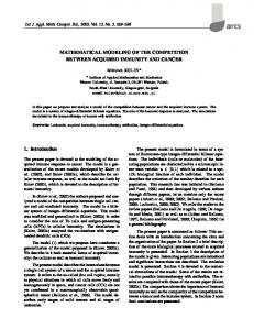
2. MODELLING OF MOTION OF DRIVE ELEMENTS AND ACTUATING MECHANISM OF RING-BALL MILL The electromechanical system of ring-ball mill (Fig. 1) includes asynchronous motor 1, combined clutch 2, reduction gear 3 and mechanism for crushing of lump material (coal) 4. Rotational movement of the motor’s rotor is transmitted through the combined clutch 2 to the driving gear’s shaft 5 and then by using the gear wheels 6 and 7 – to the intermediate shaft 8 and by using the gear wheels 9 and 10 – to the driven (main) shaft 11. Simultaneously, driven shaft 11 sets in motion the yoke 12 fixed on shaft with installed on it bottom ring 13. The ring 13, in turn, implements in motion a hollow balls 14, which are pressed to yoke by upper (screw) ring 15 and compressed springs 16 that are mounted on guides 17. In the process of rotation of the driven shaft 11 with the yoke 12 and the bottom ring 13, the balls 14 simultaneously roll on surfaces of lower and upper rings crushing coal that supplies into the mill through the pipeline 18 (direction of coal’s supply is marked by thick arrows). Milled coal with air flow, which is served in the oven cavity through the pipeline 19, is carried out through a separator 20 through pipelines 21, 22 into the power’s oven (direction of motion of coal dust mixture with air marked by thin lines). Combined clutch 2 includes a self-managed centrifugal clutch with a shot and consistently connected to it elastic clutch. Interaction of semiclutches of centrifugal clutch is carried out by the emergence of friction forces of metal shot against cylindrical surface of driven semi-clutch as a result of rotation of the working environment (steel shot) in the clutch’s cavity by using of blades of driving semi-clutch. In the initial period of start of the drive system, the moment of clutch’s friction is so small that the driving semi-clutch, which is rigidly connected to the motor’s shaft, slips against driven semi-clutch. This greatly facilitates the acceleration of the motor’s rotor. With increase of angular velocity of driving semi-clutch and accordingly with
Fig. 1. The scheme of ring-ball mill
Mechanical system of ring-ball mill, which is in non-stationary modes, has a variable structure. If there is slippage in the clutch, the system is divided into two subsystems, calculation models are shown in Fig. 2, а, where J1 – rotor moment of inertia; J2, J3 – reduced to a driving gear’s shaft moment of inertia of the gear’s mechanism rotating parts and moment of inertia of mechanism for crushing coal; c2, ν2 – reduced to a driving gear’s shaft coefficients of stiffness and viscous friction of main gear’s shaft; ME – electromagnetic moment of asynchronous motor; Mμ – moment of dry friction in the centrifugal clutch with a shot; M0 – reduced to a driving gear’s shaft moment of forces of the yoke’s technical load; φ1, φ2, φ3 – reduced to a driving gear’s shaft angular coordinates of motion of system elements. If slippage of centrifugal clutch with shot is missing, inertial elements of a system perform joint movement. This case corresponds to calculated model of ring-ball mill, which is shown in Fig. 2, b, moreover, kμ – coefficient of proportionality between moment of friction in the clutch and the square of the angular velocity of the motor’s rotor; c1, ν1 – coefficient of stiffness and coefficient of the unit viscous friction that includes the motor’s shaft, combined clutch and fast-speed gear’s shaft.
DIAGNOSTYKA, Vol. 18, No. 1 (2017) 28 Kharchenko Y, Dragun Ł. Mathematical modeling of unsteady processes in electromechanical system of …
J 3 3 3
dJ 3 3 32 d 3
2
c2 3 2 2 3 2 M 0 .
So, if there is slippage in centrifugal clutch with shot, the motion of the mechanical system of ball mill is described by differential equations (1), (2), (5), (9), (10). The initial conditions of integration of these equations are written down as j (0) 0 ; j (0) 0 (j = 1, 2, 3). (11)
a
If there is no slippage in the clutch (Fig. 2, b), expressions of kinetic and potential energies of the system take the form 2 J 2 J 2 J Ek 1 1 2 2 3 3 3 ; (12) 2 2 2
b Fig. 2. Calculated models of mechanical system of ring-ball mill
If there is slippage in clutch (Fig. 2, a), the equation of rotational motion of motor’s rotor is written down on the principle of D'Alembert, J11 M E M , (1) where ω1 – angular velocity of the rotor, (2) 1 1 . As the supply of coal in the mill working area via conveyor is not constant, reduced moment of inertia of mechanism for coal crushing during work of mill is assumed as variable. So, the equation of gear’s motion and associated with it actuating mechanism is written down on the second kind Lagrange equation d Ek Ek E p (j = 2, 3, …, n), (3) Qj dt q j q j q j where Ek, Ep – kinetic and potential energies; qj – generalized coordinate; Qj – generalized nonconservative force; t – time; n – number of freedom degrees of mechanical subsystems. Taking physical values φ2, φ3 as generalized coordinates, kinetic energy of a subsystem can be written down as 2 J 2 J Ek 2 2 3 3 3 , (4) 2 2 where ω2, ω3 – reduced angular velocities of rotating parts of gearbox and yoke, (5) 2 2 ; 3 3 . Potential energy of the subsystem
Ep
c2 2 3
(10)
2
. (6) 2 Generalized non-conservative forces are identified as (7) Q2 M 2 2 3 ; Q3 2 3 2 M 0 .
(8)
Defining the derivatives of expressions (4), (6) and substituting them in the second kind Lagrange equation (3) and taking into account dependencies of generalized non-conservative forces (7), (8), we get equations of motion of gearbox’s rotating parts and moving elements of the mill’s actuating mechanism. J 2 2 c2 2 3 2 2 3 M ;
(9)
Ep
c1 1 2
2
c2 2 3
2
. (13) 2 2 Generalized forces Q1 and Q2 in this case are defined as (14) Q1 M E 1 (1 2 ) ; Q2 1 2 1 2 2 3 ,
(15)
and generalized force Q3 retains the form (8). Substituting the appropriate derivatives of functions (12), (13) to an equation (3) and considering interrelation (8), (14), (15), we get J11 с1 1 2 1 1 2 M E ; (16)
J 2 2 с1 2 1 c2 2 3 2 2 3 0 ;
J 3 3 3
dJ 3 3 32 d 3
2
(17)
c2 3 2 2 3 2 M 0 .
(18)
Consequently, in the absence of slippage in the centrifugal clutch with the shot, the motion of the mechanical system is described by differential equations (2), (5), (16)–(18). The initial conditions for this phase of motion are defined as the shift and velocities of the relevant elements of the system at the end of the previous stage, which is accompanied by slippage in the clutch. The moment of friction in the centrifugal clutch with shot is written according to [5] M k 12 sgn 1 2 , (19) moreover,
k
2mr2 r23 r13 3 r22 r12
,
(20)
where m – mass of a shot, buried in the cavity of a clutch; μ – coefficient of shot’s friction on the cylindrical surface of driven semi-clutch; r1, r2 – radii of internal and external cylindrical surfaces that limit granular medium (shot) in working order. Reduced to the motor’s shaft moment of inertia of the actuating ring-ball mill mechanism is determined by the formula
DIAGNOSTYKA, Vol. 18, No. 1 (2017) 29 Kharchenko Y, Dragun Ł. Mathematical modeling of unsteady processes in electromechanical system of …
J3
J y J e J br 2 2 1 2
,
(21)
uu where Jy, Je – moments of inertia of yoke and granular medium (coal); u1, u2 – transmission ratio of reduction gear wheels; Jbr – reduced to the main mill’s shaft moment of inertia of the balls, R2 z J (22) J br b mb 2b , 4 rb1 moreover, mb, Jb – mass and axial moment of inertia of the hollow ball; rb1 – external radius of the ball; Rb – radius of the circumferential trajectory of ball’s gravity center; z – number of balls in the mill’s actuating mechanisms. Values mb and Jb are calculated using known formulas 4 8 mb b rb31 rb32 ; J b b rb51 rb52 , (23) 3 15 where ρb – density of ball material; rb2 – the internal radius of the ball. If the start of the electromechanical system of the mill is performed in the presence of coal in crushing mill and workload of the mill is maintained constantly, then Je remains constant value. In the case of a phased launch of the electromechanical system, during which it first (for 0 ≤ t ≤ t1) accelerats idle and then (for the time t1 ˂ t ≤ t2) gradually fills coal in the work area of the mill to achieve the rated (nominal) load, and then (for t > t2) mill’s load keeps constant, the value Je is given as J e J e1 , if t t1 ; J e J e1
J e 2 J e1 t t1 , t2 t1
if t1 t t2 ;
(24) J e J e 2 , if t t2 , where Je1, Je2 – values of moments of inertia of granular medium, which is in the crushing cell in idle mode and in established mode of the mill. The component with derivative dJ3/dφ3, which appears in the equation (18), presented as 32 dJ 3 3 dJ 3 . (25) 2 d 3 2 dt Taking into account (21), (24), (25), mentioned part of the equation (18) for the case of a phased start of electromechanical system is written as 32 dJ 3 0 , if t t1 ; 2 d 3 32 dJ 3 3 J e 2 J e1 , if t1 t t2 ; 2 d 3 2u12u22 t2 t1
32 dJ 3 0 , if t t2 , (26) 2 d 3 Moment of forces of yoke’s technological load, which is reduced to the driving gear shaft, is given as z k f 3 2i sgn 3 M0 M m M a sin , (27) u1u2 z i 1 2u1u2
where Mm, Ma – average and peak values of moment of yoke’s technological load; kf – parameter of frequency of technological load that is equal to the number of periods of technological load change during one complete rolling of a ball on the circular trajectory on the lower (supporting) ring. Average number of moment of yoke’s technological load Mm depends on the mass of coal that is in the working area of the mill and its amplitude Ma – on strength characteristics of coal and size of its pieces. If the start of the electromechanical system is performed under the load (coal is in the mill) and workload of the mill is maintained constantly, then Mm and Ma remain constant values. In the case of a phased launch of the electromechanical system, the values Mm and Ma are given as M m M m1 , if t t1 M m M m1
M m 2 M m1 t t1 , t2 t1
if t1 t t2 ;
(28) M m M m 2 , if t t2 ; M a 0 , if t t1 (29) M a M a1 , if t t1 , where Mm1 – moment of resistance of yoke motion, caused by the forces of friction in an idle mode of mill’s mechanical system; Mm2, Ma – average and peak values of yoke’s technological load in steady (nominal) mode of the mill. The systems of differential equations (1), (2), (5), (9), (10) and (2), (5), (16)–(18) are created in generalized form for the convenience of computer algorithm creation and problem solving (30) ; , where 1 , 2 , 3 ; T
1 , 2 , 3 ; T
1 M E M1 J1 1 , (31) M1 M 2 J2 2 1 dJ 3 3 3 M 2 M0 J d 2 3 3 3 moreover, moments of interaction between system elements M1 c1 1 2 1 1 2 , if c1 1 2 1 1 2 M ;
M1 M sign c1 1 2 1 1 2 , if c1 1 2 1 1 2 M ;
(32)
(33) M 2 c2 2 3 2 2 3 ; index “T” indicates matrix transposition. In the notations of moments that appear in expressions (31)–(33), the indices indicate affiliation of parameters to the relevant elastic elements of the system.
DIAGNOSTYKA, Vol. 18, No. 1 (2017) 30 Kharchenko Y, Dragun Ł. Mathematical modeling of unsteady processes in electromechanical system of … Under the first condition (32) angle of slippage in the clutch φμ remains the same. If the second condition (32) is valid, then after determining torque, the value of specified angle is refining by the formula 1 2 1 1 2 с1
M
sign c1 1 2 1 1 2 . (34) c1 During the process of numerical integration of differential equations (30) using software libraries, recalculation of the angle φμ on each step of integration by formula (34) can be labored. In that case the set of equations (30) will be augmented by differential equation , (35) where ωμ – the velocity of slippage of driving semiclutch regarding the driven one, 0 , (36)
if the first condition (32) is valid; 1 1 2 1 1 2 dt с1 M sign c1 1 2 1 1 2 , (37) c1 if the second condition (32) is valid. 3. THE EQUATION OF ELECTROMAGNETIC PROCESSES IN ASYNCHRONOUS MOTOR The differential equations of electromagnetic transients in asynchronous motor are represented in the form of [25] dis As (u s s Rs is ) Bs (r r Rr ir ) , dt dir Ar (r r Rr ir ) Br (us s s Rs is ) , (38) dt where is, ir, us – matrixes-columns of stator and rotor current’s projections on coordinate axises x, y and a matrix-column of voltage projections; As, Bs, Ar, Br – matrixes of links; s, r – matrixes of angular velocities; s, r – matrixes-columns of magnetic linkages; Rs, Rr – active resistances of stator and rotor windings. The index s specifies an inhering of magnitude to a stator winding, and r – to a rotor winding. Matrixes-columns is, ir and us are determined by means of dependencies
i j ( j s, r )i jx , i jy ; us U m , 0 , where ijx, ijy – projections of currents to axes of coordinates x, y; Um – a peak voltage of a network. Square matrixes As, Bs, Ar, Br are determined by dependencies As s (1s G), Bs s r G, Ar r (1r G), Br Bs , where T
T
G
2 2 1 Rix Tiy R T ix iy , 2 im RT ix iy Tix2 Riy2
1 1 , T . s r s r Here im, ix, iy – a current of magnetization and its components along axes x, y; , – the magnitudes that are determined on a curve of magnetization, which represents dependence of working magnetic linkage m on a current of magnetization im; s, r – magnitudes that are inversed to inductances of diffusings of stator and rotor windings. Matrixes of angular velocities 0 0 0 0 1 , , s p0 r p0 0 0 0 1 0 moreover R
where 0 – synchronous angular velocity of the motor; p0 – number of magnetic-poles pairs. Matrixes-columns of full magnetic linkages of stator and rotor windings look like T 1 1 1 1 s is i , r ir i , where i ix , iy . s r Magnitudes
ix isx irx ,
iy isy iry ,
im ix2 iy2 .
Values i are determined by dependencies i di m , m . (39) m d m The electromagnetic moment of the motor is discovered by formula 3 1 (40) M E p0 irx isy iry isx . 2 Curve of magnetization is represented in the form of m a1im a2im3 a3im5 , if im imk ;
m m1 , if im imk . (41) where imk – critical value of a current of magnetization, which overflow affects m(im) and it becomes nonlinear. Thus, and , according to dependencies (39), (41), acquire an aspect a1 a2im2 a3im4 , if im imk ; (42) m , if im imk ; a1 3a2im2 5a3im4 , if im imk ; (43) m , if im imk . Presence of the information in computer memory about a curve of magnetization (41) during a numerical integration of the equations (38) is not obligatory, as the dependencies (42) and (43) are used in the calculation. Projections of vectors of currents to axes of coordinates in an initial instant are accepted as zero: isx 0 0 , isy 0 0 , irx 0 0 , iry 0 0 . (44)
DIAGNOSTYKA, Vol. 18, No. 1 (2017) 31 Kharchenko Y, Dragun Ł. Mathematical modeling of unsteady processes in electromechanical system of … 4. ANALYSIS RESULTS OF THE ELECTROMECHANICAL SYSTEM OF RING-BALL MILL STARTING PROCESSES The calculation of the electromechanical system of ring-ball mill starting processes is reduced to numerical integration of differential equations system (30), (35), (38) taking into account correlations (19)–(24), (26)–(29), (31)–(34), (36), (37), (40), (42), (43) and initial conditions (11), (36), (44). Dynamic phenomena that occur in non-stationary modes of mill type EM-70 are analyzed to identify opportunities to reduce operational loads of the main shaft. Initial data for calculation is following. Motor 4А355М8У3: Rs = 1,288·10-2 Ω; Rr = = 1,004·10-2 Ω; Ls = 2,558·10-4 H; Lr = 3,412·10-4 H; Lm = 6,635·10-3 H; Um = 310,5 V; а1 = 3,448·10-2 Wb/А; а2 = –1,413·10-5 Wb/А3; а3 = 4,049·10-9 Wb/А5; іmk = 170,0 А; ω0 = 78,50 rad/s; p0 = 4. The mechanical part of the drive: J1 = 10,0 kg·m2; J2 = 27,26 kg·m2; c1 = 9,532·104 N·m/rad; c2 = 2,319·104 N·m/rad; ν1 = 5,0 N·m·s/rad; ν2 = 5,0 N·m·s/rad; u1 = 3,652; u2 = 4,156. The centrifugal clutch with a shot: m = 42,0 kg; rc1 = 0,140 m; rc2 = 0,230 m; μ = 0,2; kμ = 0,292. Actuating mechanism of the mill: Jy = 3,344·103 kg·m2; rb1 = 0,2650 m; rb2 = 0,1790 m; ρ = 7800,0 kg/m3; z = 9; Rb = 0,6475 m; mb = 420,0 kg; Jb = 14,66 kg·m2; Jbr = 593,2 kg·m2; Je1 = 0,0; Je2 = 3,950·103 kg·m2; J3 = 17,09 kg·m2 for unloaded mill; J3 = 34,24 kg·m2 – for loaded mill. Start of the electromechanical system with coal in mill chamber (start under load) is illustrated on Fig. 3–5. While calculation, technological load characteristics were set as following: Mm = 20,0 kN·m; Ma = 5,0 kN·m; kf = 10,0. High-frequency oscillations of the motor’s electromagnetic moment at the beginning of the transition process (Fig. 3, a) are occurring at a frequency which is close to the frequency of electric oscillations in the power supply network. The change in the technological load period (Fig. 3, b) is caused by the increasing of angular velocity of the main shaft of the mill. Fig. 4, a illustrates specifics of increase in angular velocity of motor’s rotor and in angular velocity of rotating parts of the reduction gear and shows the transition from the movement of system with slipping in centrifugal clutch with shot (duration 5.30 s) to the movement of system without slipping in the specified clutch. Time dependence of the yoke’s angular velocity (Fig. 4b) in its form roughly follows the time dependence of angular velocity of the driving gear wheel of the reducer (Fig. 4a). a)
b)
Fig. 3. Time dependences of the motor’s electromagnetic moment (a) and moment of forces of technological load (b) during the start of the electromechanical system of the mill under load
A sharp change of moment in combined clutch at time, when the slipping is ceasing, is causing the appearance of mechanical oscillations in the system (Fig. 5, a). Due to the change of technological load frequency while the mill’s actuating mechanism acceleration, transitions through the resonance phenomenon are possible, which cause significant increase of torque amplitude in the main shaft (Fig. 5, b). a)
b)
Fig. 4. Time dependences of the motor’s rotor angular velocity (a, curve 1), driving gear wheel of reducer (a, curve 2) and yoke’s (b) during the start of the electromechanical system of the mill under load
DIAGNOSTYKA, Vol. 18, No. 1 (2017) 32 Kharchenko Y, Dragun Ł. Mathematical modeling of unsteady processes in electromechanical system of … a)
a)
b)
b)
Fig. 5. Time dependencies of friction torque in the clutch (a, curve 1), of moment of elastic forces of the clutch (a, curve 2) and of moment of elastic forces of the main shaft (b) during the start of the electromechanical system of the mill under load
The process of phased start of mill’s electromechanical system (Fig. 6-8) includes idle start of the system that durates 3 s, its movement with even increase of the average value of technological load from zero to 20 kN·m and periodic component of load with amplitude 5 kN·m during 5 s and smooth transition to the steady motion of the system within the next 2 s. Lack of technological load on the first stage of the system’s motion facilitates acceleration of gear’s elements and actuating mechanism. Time of the mechanical system’s motion during slippage mode in centrifugal clutch with shot lasts approximately 1,67 s (Fig. 7, a). The frequency of technological load’s change, which takes effect on the second stage of motion (Fig. 6, b), can be considered constant with some approximation (coefficient of frequency kf = 10.0). Transition to the system motion without slippage in the clutch, as in the previous case, accompanies by cause of torque in elastic knot, which is formed by combined clutch and parts of coupled with it shafts (Fig. 8, a). Variable technological load in the beginning of the second phase of motion causes resonant oscillation of torque in the main shaft of the mill (Fig. 8, b). The amplitude of these oscillations decreases with time, which can be explained by the growth of reduced moment of inertia of the actuating mechanism due to the load of the working cell of the mill.
Fig. 6. Time dependencies of electromagnetic moment of the motor (a) and moment of forces of technoligical load of the yoke (b) during the phased start of electromechanical system of the mill
Research of dynamic phenomena that occur in nonstationary modes of the mill shows that parameters of technological load and torsional rigidity of the main shaft significantly affect the maximum value of torque in the main shaft (Fig. 9, 10). Duration of the mill’s working cell filling 5 s can be considered quite reasonable, since its increase does not lead to a significant reduction of the maximum torque in the main shaft (Fig. 11). a)
b)
Fig. 7. Time dependencies of angular velocity of the motor’s rotor (а, curve 1), driving gear wheel of the reducer (а, curve 2) and yoke (b) during the phased start of electromechanical system of the mill
DIAGNOSTYKA, Vol. 18, No. 1 (2017) 33 Kharchenko Y, Dragun Ł. Mathematical modeling of unsteady processes in electromechanical system of … a)
Fig. 11. Dependencies of maximum torque in the main shaft on frequency parameter of technological load during the phased start of the ring-ball mill for values of load time of working cell: 1 – t2 = 5,0 s; 2 – t2 = 15,0 s
b)
5. CONCLUSIONS
Fig. 8. Time dependencies of moment of friction in the clutch (а, curve 1), moment of elastic forces of the clutch (а, curve 2) and moment of elastic forces of the main shaft (b) during the phased start of driving system of the mill
Fig. 9. Dependencies of maximum torque in the main shaft on frequency parameter of technological load during the start of electromechanical system of the mill under the load: 1 – Mm = 5,0 kN·m; 2 – Mm = 15,0 kN·m; 3 – Mm = 20,0 kN·m; 4 – Mm = 25,0 kN·m; 5 – Mm = 30,0 kN·m.
Fig. 10. Dependencies of maximum torque in lowspeed shaft of the reducer on frequency parameter of technological load during the start of driving system of the mill under the load: 1 – с2 = 1,0 kN·m/rad; 2 – с2 = 10,0 kN·m/rad; 3 – с2 = 20,0 kN·m/rad; 4 – с2 = 25,0 kN·m/rad
1. Here is developed the nonlinear mathematical model of nonstationary processes in electromechanical system of ring-ball mill considering interference of electromagnetic phenomena in asynchronous motor and mechanical vibration phenomena, possible changes of the structure of the mechanical subsystem of engine during the start, features of the functioning of the centrifugal clutch with shot, as well as the unsteady of consolidated moment of inertia and technological load parameters during the loading process or unloading of the mill working cell. The numeric implementation of mathematical model enables to determine the maximum efforts in elements of the mill construction and the features of changes of these efforts over time, that facilitate the accuracy of calculations of the ring-ball mills on strength and improve methods of forecasting its design or remaining life. 2. Research has shown that the maximum moments in the main shaft can twice values during the start process of electromechanical system of ring-ball mill under the load than during the phased start of the engine. The average value, the amplitude and frequency parameter of technological load, as well as twisting rigidity of the main shaft significantly affect the maximum value of torque in the main shaft. In the range of values of the technological load frequency parameter kf = 15 – 20 during the start of mill’s electromechanical system can occur a conversion through resonance. 3. The use of elastic clutch for transmitting of rotational motion from the main shaft to yoke of the ring-ball mill actuating mechanism can be considered as an important factor in reduction of the maximum torque in the main shaft. Reduction of the twisting stiffness of the shaft lines from 25,0 kN·m/rad to 10,0 kN·m/rad enables to reduce the torque in the specified shaft for 14,2 % and further reduction of this stiffness to 1,0 kN·m/rad enables to avoid resonance phenomena and reduce torque on the main shaft for 29,8 %.
DIAGNOSTYKA, Vol. 18, No. 1 (2017) 34 Kharchenko Y, Dragun Ł. Mathematical modeling of unsteady processes in electromechanical system of … REFERENCES 1.
2.
3.
4.
5.
6.
7.
8.
9.
10.
11.
12.
13.
14.
Agrawala V.; Panigrahia B.K.; Subbaraob P.M.V. 2015. Review of control and fault diagnosis methods applied to coal mills, Journal of Process Control, 32, 138–153. http://dx.doi.org/10.1016/j.jprocont.2015.04.006 Bhambare K.S.; Ma Z.;, Lu P. 2010. CFD modeling of MPS coal mill with moisture evaporation, Fuel Processing Technology, 91, 566–571. http://dx.doi.org/10.1016/j.fuproc.2010.01.002 doi:10.3103/S1068371209090090 Chattopadhyay P. P.; Mannaa I.; Talapatra S.; Pabi S.K. 2001. A mathematical analysis of milling mechanics in a planetary ball mill, Materials Chemistry and Physics, 68, 85–94. http://dx.doi.org/10.1016/S0254-0584(00)00289-3 Crowthe A. R.; Zhang N. 2005. Torsional finite elements and nonlinear numerical modelling in vehicle powertrain dynamics, Journal of Sound and Vibration, 284, 825–849. http://dx.doi.org/10.1016/j.jsv.2004.07.022 Dietrich M. 2015. Podstawy konstrukcji maszyn, t.3, Wydawnictwo Naukowo Techniczne, Warszawa, Wydanie 3, 2015 (in Poland). Ding Y.; He W.; Chen B.; Zi Y.; Selesnick I. V. 2016. Detection of faults in rotating machinery using periodic time-frequency sparsity, Journal of Sound and Vibration, 382, 357–378. http://dx.doi.org/10.1016/j.jsv.2016.07.004 Duan C.; Singh R. 2006. Dynamics of a 3dof torsional system with a dry friction controlled path, Journal of Sound and Vibration, 289, 657–688. http://dx.doi.org/10.1016/j.jsv.2005.02.029 Fan G.Q.; Rees N.W.; 1997. Intelligent expert system (KBOSS) for powerplant coal mill supervision and control, Control Eng. Pract., 5, 101– 108. doi:10.1016/S0967-0661(96)00213-4 Huang J. L.; Su R.K.L.; Lee Y.Y.; Chen S.H. 2011. Nonlinear vibration of a curved beam under uniform base harmonic excitation with quadratic and cubic nonlinearities, Journal of Sound and Vibration, 330, 5151–5164. http://dx.doi.org/10.1016/j.jsv.2011.05.023 Junga R.; Mateuszuk S.; Pospolita J. 2009. Investigations into the movement of milled medium in the bowl of a ring-roller mill, Elsevier, Powder Technology, 191, 61–71. http://dx.doi.org/10.1016/j.powtec.2008.09.015 Kim T. C.; Rook T. E.; Singh R. 2005. Super- and sub-harmonic response calculations for a torsional system with clearance nonlinearity using the harmonic balance method, Journal of Sound and Vibration 281, 965–993. http://dx.doi.org/10.1016/j.jsv.2004.02.039 Kojovic T.; Shi F.; Brennan M. 2015. Modelling of vertical spindle mills. Part 2: Integrated models for E-mill, MPS and CKP mills, Fuel, 143, 602–611. http://dx.doi.org/10.1016/j.fuel.2014.11.015 Lee C. W.; Han D. J. 2008. Strength of modes in rotating machinery, Journal of Sound and Vibration, 313, 268–289. http://dx.doi.org/10.1016/j.jsv.2007.11.038 Niemczyk P.; Bendtsen J.D.; Ravn A.P.; Andersen P.; Søndergaard P. T. 2012. Derivation and validation of a coal mill model for control, Control Engineering Practice, 20, 519–530. http://dx.doi.org/10.1016/j.conengprac.2012.01.006
15.
16.
17.
18.
19.
20.
21.
22.
23.
24.
25.
26.
27.
Parida N.; Tarafder S.;Das S.K.; Kumar P.; Das G.; Ranganath V. R.; Bhattacharya D. K. 2003. Failure analysis of coal pulverizer mill shaft, Pergamon, Engineering Failure Analysis, 10, 733–744. http://dx.doi.org/10.1016/S1350-6307(02)00070-5 Pennacchi P. 2009. Robust estimation of excitations in mechanical systems using M-estimators – Experimental applications, Journal of Sound and Vibration, 319, 140–162. http://dx.doi.org/10.1016/j.jsv.2008.05.017 Puchała A. 1977. Dynamika maszyn i układów elektromechanicznych, Polskie Wydawnictwo Naukowe, Warszawa (in Poland). Qinkai H.; Jingshan Z.; Fulei C. 2012. Dynamic analysis of a geared rotor system considering a slant crack on the shaft, Journal of Sound and Vibration, 331, 5803–5823. http://dx.doi.org/10.1016/j.jsv.2012.07.037 Shah K. V.; Vuthaluru R.; Vuthaluru H. B. 2009. CFD based investigations into optimization of coal pulveriser performance: Effect of classifier vane settings, Fuel Processing Technology, 90, 1135– 1141. http://dx.doi.org/10.1016/j.fuproc.2009.05.009 Shi F.; Kojovic T.; Brennan M. 2015. Modelling of vertical spindle mills. Part 1: Sub-models for comminution and classification, Fuel, 143, 595–601. http://dx.doi.org/10.1016/j.fuel.2014.10.085 Søren B. A.; Søren E.; Ilmar F. S. 2013. Dynamics and stability of rigid rotors levitated by passive cylinder-magnet bearings and driven / supported axially by pointwise contact clutch, Journal of Sound and Vibration, 332, 6637–6658. http://dx.doi.org/10.1016/j.jsv.2013.07.006 Sorge F.; Cammalleri M. 2010. Control of hysteretic instability in rotating machinery by elastic suspension systems subject to dry and viscous friction, Journal of Sound and Vibration, 329, 1686– 1701. http://dx.doi.org/10.1016/j.jsv.2009.12.007 Tchaban V.; 2010. Mathematical modeling in electrical engineering. T. Soroka Publisher House, Lviv (in Ukrainien). Walker P. D.; Zhang N. 2012. Investigation of synchronizer engagement in dual clutch transmission equipped power trains, Journal of Sound and Vibration, 331, 1398–1412. Xie W.; He Y.; Zhang Y.; Huang Y.; Li H.; Wei H.; Wang H. 2015. Simulation study of the energy-size reduction of MPS vertical spindle pulverizer, Fuel 139, 180–189. http://dx.doi.org/10.1016/j.fuel.2014.08.040 Yang Y.; Dong X. J.; Peng Z. K.; Zhang W. M.; Meng G. 2015. Vibration signal analysis using parameterized time – frequency method for features extraction of varying - speed rotary machinery, Journal of Sound and Vibration, 335, 350–366. http://dx.doi.org/10.1016/j.jsv.2014.09.025 Zhou Y. D.; Liu Y. L.; Tang X. W.; Cao S. Q.; Chi C. J. 2014. Numerical investigation into the fragmentation efficiency of one coal prism in a roller pulveriser: Homogeneous approach, Minerals Engineering, 63, 25–34. http://dx.doi.org/10.1016/j.mineng.2013.10.022
Received 2016-12-24 Accepted 2016-02-21 Available online 2017-03-23
DIAGNOSTYKA, Vol. 18, No. 1 (2017) 35 Kharchenko Y, Dragun Ł. Mathematical modeling of unsteady processes in electromechanical system of … Yevhen KHARCHENKO, Prof., dr hab. eng. – works at Department of Mechanics and Bases of Designing in University of Warmia and Mazury in Olsztyn. In scientific work conducts research in the theory of linear and nonlinear vibrations of discrete-continuum mechanical systems. Engaged in problems of dynamics, strength and technical diagnostics of machines and engineering structures. The author of about 300 scientific papers, including 2 monographs. Łukasz DRAGUN, M. Sc. Eng. – works at Faculty of Management in Bialystok University of Technology. In scientific work conducts research in the diagnostics, construction and maintenance of machinery, total productive maintenance and production engineering. The author of about 20 scientific papers.