173
1
Matrix based Cryptographic Procedure for Efficient Image Encryption Paul A.J
P. Mythili
K. Paulose Jacob
Musaliar College of Engineering and Technology, Pathanamthitta, Kerala.
[email protected]
Cochin University of Science and Technology, Kochi, Kerala.
[email protected]
Cochin University of Science and Technology, Kochi, Kerala.
[email protected]
Abstract- In this paper we propose a cryptographic transformation based on matrix manipulations for image encryption. Substitution and diffusion operations, based on the matrix, facilitate fast conversion of plaintext and images into ciphertext and cipher images. The paper describes the encryption algorithm, discusses the simulation results and compares with results obtained from Advanced Encryption Standard (AES). It is shown that the proposed algorithm is capable of encrypting images eight times faster than AES. Index Terms- Ciphertext, Decryption, Encryption, Plaintext, Secret key, Sub key.
I. INTRODUCTION In the recent years protection of multimedia data is becoming more important [1]. Image and video encryption has application in various fields including internet communications, multimedia systems, medical imaging, Telemedicine and military communications [2]. Secure communication of images requires encryption at the sending side and decryption at the receiving side. Encryption of large images takes time before they can be transmitted thereby causing considerable delay in successive transmission of encrypted images. In order to minimize the latency, efficient encryption algorithms are needed. An encryption procedure with adequate security and high throughput is sought in multimedia encryption applications. Traditional block ciphers like DES (Data Encryption Standard) [3] and AES (Advanced Encryption Standard) [4] are not efficient when image size is large [5]. Symmetric key cryptography and public key cryptography are available for encryption of information. Public-key algorithms are slow, whereas Symmetric-key algorithms generally run much faster [6]. Symmetric-key cryptography has been (and still is) extensively used to solve the traditional problem of communication over an insecure channel [7]. High throughput encryption and decryption are becoming increasingly important in the area of high-speed networking [8,9]. Fast encryption algorithms are needed these days for high-speed secure communication of multimedia data [10]. In this paper a fast symmetric key encryption procedure, Matrix Array symmetric Key Encryption (MASK) based on matrix manipulation is presented. The encryption scheme presented here is a block cipher with a block size of 128 bits and key size of 128 bits. Rest of the paper is organized in the following sections. In section II, encryption process is explained and in section III, Simulation results are presented and compared with Advanced Encryption Standard. A basic
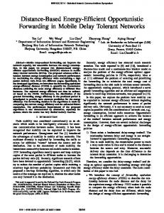
security analysis, through statistical approach, is offered in section IV and conclusions are made in section V. II. ENCRYPTION PROCESS A. Encryption Steps The encryption, C = Ek(P), using the proposed encryption algorithm consists of three steps. The first step involves initialization of a matrix M using secret key K and generation of two matrices of sub keys Ks1 and Ks2 for iterative substitution and diffusion round operations. The second step involves substitution and diffusion operations iterations. Fig.1 shows the block diagram of encryption process. The iterative round operations are shown in boxes with dotted lines. Plaintext block P
Secret Key K
Substitution
Matrix M
Substitution & Diffusion Round #1 Ks1[1] L
R
T Subkey set for 1st round
T
Ks2[1]
>>> >>>
Substitution
Matrix M
Substitution & Diffusion Round #16 Ks1[16] L
R
T Subkey set for 1st round
T
Ks2[16]
>>> >>>
Ciphertext block C
Figure 1. Simplified block diagram of encryption process.
978-1-4244-9477-4/11/$26.00 ©2011 IEEE
174
B. Matrix initialization A matrix M with 16 rows and 256 columns is defined. Each column of every row is filled with a number between 0 and 255 (both the numbers included) in an order depending on the characters of secret key. The first column in the ith row of the matrix is filled with integer value of ith character of the secret key, K (that is, M[i][1] = Integer value of K[i]). The subsequent columns of the ith row of the matrix are filled with numbers that have increments of 1 from the previous column value till the number is 255. Subsequent columns are filled with numbers starting from 0 and ending with integer value of the ith character of secret key minus 1. The distribution of characters in the columns of all the sixteen rows of the matrix thus becomes key dependent. Without knowing the secret key the element in a column of any row of the matrix M cannot be determined by an adversary. Plate 1. shows the matrix initialization pseudo code.
4) 5)
6) 7)
8)
9)
For i Å 0 to 15 // rows For j Å 0 to 255 // columns M[i][j] = (int)K[i] + j If M[i][j] > 255 { M[i][j] = M[i][j] – 256 } EndFor // columns EndFor // rows Plate 1. Matrix initialization pseudo code.
C. Key schedule. Sub-keys used in round operations are generated by key scheduling procedure. In this procedure two sub-key matrices Ks1 and Ks2 ( of size 16 x 16 ) are derived from the base matrix M. These pairs of key can be used in substitution and diffusion operations performed in a typical block cipher. It is desirable that the key scheduling be a complex procedure so that an adversary must find it extremely difficult to derive the sub-keys during crypt analysis. Another desirable feature of key schedule is that a small change in the secret key should get well diffused in to the sub-keys. This means that one bit change in secret key should cause many bits to change in subkeys. These two desirable features are considered while designing the key scheduling procedure. The procedure is explained in steps as follows: 1) Secret key, K, is transposed (T) to get Ka1. It is a byte-level transposing operation where by the LS byte takes the place of MS byte position and the MS byte takes the LS byte position after the transpose operation. For example, if, bytes in array, K, is {K0,K1,K2,K3,….K14,K15} then, after performing the transpose operation, Ka1 = K Transposed, the contents of Ka1 will become {K15, K14,….K5,K4,K3,K2,K1,K0}. 2) Ka1 is XOR ed with K to get Ka2. This operation can cause up to 2 bits to change in Ka2 when 1 bit is changed in secret key K. 3) Left half of Ka2 and right half of Ka2 is XOR ed to
10) 11)
2
get Ka3. Transposed left half of Ka2 and transposed right half of Ka2 are XOR ed to get Ka4. Ka3 and Ka4 are concatenated to get Ka5. With this operation, 1 bit change in secret key, K, can cause up to 4 bits to change in Ka5. Sum of integer values of bytes in Ka5 is calculated to get L Kse1 is calculated such that Kse1 = L % 23. When secret key has 1 bit change, Kse1 can have up to 4 counts change. Kse2 is calculated such that Kse2 = L % 15. When secret key has 1 bit change, Kse2 can have up to 4 counts change and (Kse1 + Kse2) can have up to 8 counts change. Two matrices Ks1 and Ks2 of size 16 x 16 are derived from the base matrix, M, such that Ks1[row][column]=M[row][Kse1+Kse2+column] Ks2[row][column]=M[row][Ks1[row][column]] Columns of Ks1 matrix are chosen from the base matrix M depending upon Kse1 and Kse2 Values. Here, an element of Ks1 can have up to 8 count change with one bit change in secret key. Columns of Ks2 matrix are chosen from the base matrix M depending upon element values of columns of Ks1 matrix. An element of Ks2 can have up to 8 counts change with one bit change in secret key. Rotate vertically down ith column of matrix Ks1 number of times equal to ((int(K[i]) % 12) + Kse1). Rotate vertically down ith column of matrix Ks2 number of times equal to ((int(K[i]) % 10) + Kse2). The vertical rotations shuffle the elements of sub-key matrices thereby providing more changes in the subkey values while one bit change is applied on the original secret key, K. Plate 2. shows the pseudo code of key schedule procedure. Ka1 = K Transposed ; Ka2= Ka1 XOR K Ka1=Left 8 characters of K ; Ka2=Right 8 char of K Ka3= Ka1 XOR Ka2 ; Ka1= Ka1 Transposed Ka2 = Ka2 Transposed ; Ka2 = Ka2 XOR Ka1 Ka3 = Ka2 and Ka3 concatenated SUM = Integer sum of Elements of Ka3 Kse = SUM % 23 ; Kse1 = SUM % 15 For r Å 0 to 15 For i Å 0 to 15 Ks1[i][r] = M[i][(Kse+Kse1+r)] Ks2[i][r] = M[i][ ((int) Ks1[i][r] Ks1[i][r] = M[i][ (int) Ks2[i][r] Q[i] = (int)K[i] % 12 EndFor EndFor For i Å 0 to 15 Circlar shift down ith column of Ks1 & Ks2 number of times equal to Kse1+ Q[i] EndFor Plate 2. Key schedule pseudo code.
175
D. Substitution and Diffusion iterations There are up to16 iterations of substitution and diffusion in the cipher. A data block, P, consisting of 16 bytes, P(0) Æ P(15), is applied at the input of substitution and diffusion iterative round unit. Data byte, P(i) is taken and the decimal value of P(i) is used as column number, j, of the ith row of matrix M to read the value M(i,j). This value is taken as the substitute for P(i). For example, for the byte P(0) in a block, i = 0 and j = decimal value of P(0)are used to find the value M(0,,j) as substitute, C(0), for P(0). In this way, all the 16 bytes of data in a block are substituted by a value taken from selected column and row of the matrix depending on position of the data in the block and the data value. The diffusion of data is facilitated by key based XOR, data based XOR, transpose (T) and data based rotation (>>>) operations as given in the pseudo code. The output of last iteration round is taken as the ciphertext block. Number of iterations can be chosen between 1 and 16. Plate 3. shows Substitution and diffusion pseudo code. For i Å 0 to 15 j = P(i)) C(i) = M[i][j] EndFor
C=C EXOR Ks1 C=C Transpose C1=left half bytes of C C2=right half bytes of C C2=C1 EXOR C2; C1=C1 Transpose C1=C1 EXOR C2 C3=C1 || C2; C3=C3 Transpose C3=C3 EXOR Ks2 C4=Right half bytes of C3 C5=left half bytes of C3 C6=byte sum C5 C6=C6 MODE 6 Rotate right C4, C6 times C7=byte sum C4; C7=C7 MODE 6 Rotate right C5, C7 times; C=C4 || C5 P=C Plate 3. Substitution and diffusion pseudo code
III. SIMULATION RESULTS The encryption algorithm has been tested with different images of various sizes and the results are compared with AES. The simulation tests have been conducted using Matlab7 in an Intel Atom 1600 MHz processor with Windows-xp operating system. Measurement of encryption speed, encryption quality and key sensitivity tests have been made . A. Measurement of Encryption speed Encryption speed of the proposed algorithm has been measured and compared with AES. Two images of size 256 x 256 and 512 x 512 were chosen for the measurement. Table I. shows the encryption speeds observed using these images for different rounds in AES and MASK. It can be seen that MASK encryption is eight times faster than AES. The average of encryption time and decryption time is used to compute the speed in bytes / second .
3
TABLE I. COMPARISON OF ENCRYPTION SPEEDS -AES & MASK Encryption Speed (Bytes/s) of AES & MASK with different images Ciphering Rounds
Image size 256 x 256
Image size 512 x 512
Algorithm type AES
MASK
AES
MASK
1
1733.18
13842.22
1766.1179
15128.347
2
910.82
7936.06
924.77295
8027.4375
3
616.72
5391.25
602.17583
5512.4962
4
465.83
4007.95
468.90556
4183.2936
5
372.73
3310.40
378.47051
3356.4528
6
311.75
2768.50
316.0189
2797.8441
7
268.49
2340.57
272.14252
2397.0958
8
233.74
2095.04
237.90936
2092.3146
9
206.33
1819.28
211.22759
1874.2377
10
187.22
1661.12
190.5601
1683.1075
B. Measurement of Encryption Quality The encryption quality may be expressed in terms of total changes in pixel gray values between the original image and the encrypted image given by: 255
Q = e
L=0
Σ |H (F) – H (F’)| L
L
256
Where, L is the pixel gray level, HL(F) the number of pixels having gray level L in the original image and HL(F’) the number of pixels having gray level L in the encrypted image. TABLE II. ENCRYPTION QUALITY MEASURED IN AES & MASK Encryption Quality of AES & MASK with different images Image name Rice.png Liftingbody.png Ciphering (256 x 256) (512 x 512) rounds Algorithm type AE S MASK AES MASK 1 230.191 231 358.902 357.52 2 230.98 229.93 358.91 357.757 3 230.789 230.824 359.334 360.464 4 229.832 230.805 359.281 358.336 5 230.41 231.441 361.062 361.105 6 230.48 231 358.797 361.629 7 229.312 230.55 359.84 360.023 8 229.543 230.191 359.605 359.277 9 230.101 231.25 361.308 358.379 10 230.902 230.148 360.49 360.359
The encryption quality has been measured using two images. Table II shows comparison of encryption quality measured in AES & MASK. It can be seen that the encryption quality in both MASK and AES algorithms are more or less same. C. Key Space Analysis A block cipher should be sensitive to the secret keys and the key space should be large enough to resist ciphertext-only (brute-force) attack. The MASK cipher use 128 bits key size
176
that provides 2
128
key combinations.
1) Exhaustive key search An adversary may try to directly guess the secret key K. Although K is user specified, it can be generated as a random number or a set of random numbers each independent of the other. The key size is defined as 128 bits in the proposed algorithm. This means that K has 2128 possible combinations. If an adversary employs a 100 MIPS computer to find K, the computational load is 2128 / [(100 * 106) * 60 * 60 * 24 * 365] or over 10 23 years. Like any other cipher having 128 bit secret key, the MASK cipher is resistant to ciphertext-only attack. 2) Key sensitivity test In this test we first run the encryption program, MASK, with an input image, I, and a secret key, K, and obtain the cipher image, C1. Then we run the program with the same input image and another secret key that is different by one bit (closest key) with respect to the first key and obtain the cipher image, C2. Using the two encrypted images we obtain the difference image, /(C1-C2)/.
(a)
(b)
(c)
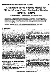
results obtained from MASK encryption is compares well with the results obtained from AES encryption. The methods of confusion and diffusion are used to frustrate powerful attacks based on statistical analysis [9]. The proposed encryption scheme, MASK, demonstrates confusion and diffusion that can stand against statistical attacks. This is shown by histograms of ciphered images and adjacent pixel autocorrelation plots. It can be seen that in all the analysis performed, the results obtained from MASK encryption is compares well with the results obtained from AES encryption. A. Histograms analysis of encrypted images We used few black & white images of different sizes and obtained the histograms of encrypted images using the proposed encryption and AES. We observe that the histograms of encrypted images have fairly uniform distribution of pixel gray values and significantly different from the original image. Fig. 3 (a1), (a2) and (a3) shows test image onion, cipher images obtained from MASK, and AES. Their respective histograms are shown in figure 3(b1), (b2) and (b3).
(a1)
(a2)
(a3)
(b1)
(b2)
(b3)
(c1)
(c2)
(c3)
(d1)
(d2)
(d3)
(e2)
(e3)
(d)
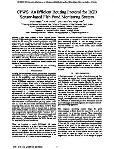
(e) (f) (g) (h) Figure 2. Encryption and decryption results using closest keys.
It has been observed that the image encrypted by the first key has 34.57 % of difference from the image encrypted by the second key in terms of pixel gray scale values although there is only one bit difference in the two keys. Fig. 2(a) shows the input image of Liftingbody, (b) shows the encryption using the first key, (c) shows encryption using the closest key and (d) shows the difference image. Decryption test is also done with the two closest keys and results were obtained. Figure 2(e) shows the input image of Liftingbody, 2(f) shows the encryption using the first key, 2(g) shows decryption using the first key and 2(h) shows the decryption using the second key which is closest to the first key. It may be noted here that the decrypted image with the closest key (key with one bit difference) does not reveal any information contained in the original image.
(e1)
IV. SECURITY ANALYSIS BY STATISTICAL APPROACH An encryption scheme must be able to resist all known attacks such as known-plaintext attack, ciphertext attack, statistical attack, differential attack and various brute force attacks. Some security analysis performed on the proposed encryption scheme includes statistical analysis and key space analysis. It can be seen that in all the analysis performed, the
4
(f1)
(f2)
(f3)
Figure 3. Selected images, encrypted images and histograms.
177
Fig. 3 (c1), (c2) and (c3) show test image Lena, cipher images obtained from MASK and AES respectively. The respective histograms are shown in fig. 3(d1), 3(d2) and (d3). Fig. 3(e1), 3(e2) and 3(e3) show test image rice, cipher images obtained from MASK, and AES respectively. Their respective histograms are shown in fig. 3(f1), 3(f2) and 3(f3). It may be noted that the histograms of encrypted images exhibits fairly uniform gray level distribution suggesting strong diffusion of pixel gray values. B. Adjacent pixel correlation analysis Correlation between two adjacent pixels along horizontal, vertical and diagonal directions has been obtained using the original images and the ciphered images. TABLE III. ADJACENT PIXEL CORRELATION OF IMAGES ENCRYPTED USING AES & MASK Correlation Coefficient Image Name
Onion
Lena
Saturn
Rice
Direction
Plain Image
MASK cipher image
AES cipher image
Horizontal
0.9889
0.0015
0.0649
Vertical
0.9870
0.0373
0.0470
Diagonal
0.9885
0.0744
0.0430
Horizontal
0.9668
0.0056
0.0374
Vertical
0.9323
0.0920
0.1380
Diagonal
0.9659
0.0749
0.0547
Horizontal
0.9976
0.2472
0.3525
Vertical
0.9969
0.0593
0.0003
Diagonal
0.9992
0.0144
0.1105
Horizontal
0.9636
0.0705
0.0416
Vertical
0.8161
0.0466
0.0268
Diagonal
0.9594
0.0036
0.1119
Horizontal
Vertical
Diagonal
4(b) shows adjacent pixel correlation plots, in horizontal, vertical and diagonal directions in the cipher image by MASK. Fig. 4(c) shows adjacent pixel correlation plots, in horizontal, vertical and diagonal directions in the cipher image by AES. The horizontal and vertical axes represent pixel gray levels in selected pairs of adjacent pixels. It can be seen that in the correlation plots of the encrypted images by MASK and AES the correlation is very low in all the three directions. This indicates that both encryptions produce uncorrelated output bytes from correlated input bytes. Table III shows a comparison of correlation coefficients in selected images and their cipher images obtained from AES and MASK encryption. V. CONCLUSION We have presented a new cryptographic algorithm, MASK, using matrix based substitution and key scheduling. The matrix-based mapping facilitates poly-alphabetic substitution. Multiple round operations depending on secret key and data values give adequate diffusion of information values. The security of the algorithm is comparable with that of AES as indicated by encrypted images, their histograms and correlation parameters. A basic security analysis has been made based on histograms of encrypted images and correlation data. The performance test results indicate the suitability of MASK for fast image encryption. It has been shown that MASK encryption is eight folds faster than AES. Additional test and analysis of the algorithm can be conducted to find the suitability of the algorithm for audio and video encryption. REFERENCES [1] [2] [3] [4]
(a) Correlation plots of image onion
[5] [6]
(b) Correlation plots of cipher image of onion (MASK)
[7]
[8] (c) Correlation plots of cipher image of onion (AES) Figure 4: Adjacent pixel correlation of image onion and encrypted images
Two adjacent vertical lines, horizontal lines and diagonal lines have been selected from the plain images and the ciphered images to obtain the correlation plot. Fig. 4(a) shows adjacent pixel correlation plots, in horizontal, vertical and diagonal directions of image onion encrypted by MASK & AES. Fig.
5
[9]
[10]
Ju Young O.H et-al, “A Selective Encryption Algorithm based on AES for Medical Information,” Health Informatic Research, Vol 16, No. 1, March 2010, pp. 22–29. M.Zeghid et-al, “A Modified AES based Algorithm for Image Encryption,” World Academy of Science, Engineering and Technology, 27 2007, pp 206 – 210. Data Encryption Standard : http://csrc.nist.gov/publications/fips/fips 46-3/fips- 46- 3.pdf Advanced Encryption Standard: http://csrc.nist.gov/publications/fips/fips197/ fips- 197.pdf Xiaogang Jia et-al, “Image Encryption using IKEDA Map,” International Conference on Intelligent Computing and Cognitive Informatics, IEEE Computer Socoety, pp. 455-458 , (2010) Jose J. Amador, Robert W. Green, “Symmetric-Key Block Ciphers for Image and Text Cryptography,” International Journal of Imaging System Technology, Vol. 15 – pp. 178-188, (2005). Dragos Trinca, “Sequential and Parallel Cascaded Convolution Encryption with Local Propagation: Toward Future Directions in Cryptography,” Proceedings of The third International Conference on Information Technology-New Generations. (ITNG’06), 0-7695-2497- 4 / 2006, IEEE Computer Society, (2006). Adam J. Elbirt, Christof Paar “An Instruction- Level Distributed Processor for Symmetric-Key Cryptography,” IEEE Transactions on Parallel and distributed Systems, Vol. 16, No. 5, May, (2005). Paul A.J., Varghese Paul, P. Mythili “Fast Symmetric Cryptography using Key and Data based Masking Operations,” International Journal of Computational Intelligence-Research and Applications. Vol. 3, No. 1, January-June 2009, pp 5–10. Krishnamoorthy G.N, V. Ramaswamy, “Encryption Quality Analysis and Security Evaluation of CAST-128 Algorithm and its Modified Version using Digital Images,” International Journal of Network Security & its Applications, Vol.1, No.1, April 2009, pp 28-33.