International Journal of Research and Reviews in Computing Engineering Vol. 1, No. 1, March 2011 Copyright © Science Academy Publisher, United Kingdom www.sciacademypublisher.com Science Academy Publisher
Matrix Converter Control Algorithm Dedicated to Feed the Double Star Induction Machine A. Azib, F. Tazerart, B.Metidji, N. Taib, DJ. Ziane and T. Rekioua Department of Electrical Engineering, University of Bejaia, Targa Ouzemour, Bejaia, Algeria Correspondence should be addressed to Author Full Name
[email protected]
Abstract – variable speed multi-phase drive systems are seen as serious contender to the existing three-phase drives due to their distinct advantages. However we present in this work the modelling and control of matrix converter feeding a double star induction machine. In order to achieve this goal we present the model of matrix converter which is an indispensable way to design control systems more efficient, and its control strategy: based on the space vector modulation (SVM). Then we perform simulation tests for the whole converter and machine using Matlab Simulink. The results illustrate the proper functioning of the system.
1.
Introduction
In the field of variable speed, the use of asynchronous machine, is very attractive for these multiple advantages such as robustness, simplicity of structure, weight, size and especially its low maintenance and low cost, can meet the specifications of demanding industrial load in terms of performance [1]. The area of multiphase variable –speed motor drives in general and multiphase induction motor drives in particular has experienced a substantial growth since the beginning of this century. Research has been conducted worldwide and numerous interesting developments have been reported in the literature. [2] The double star induction machine studied in this paper is a machine that has two systems of coupled threephase windings in the stator fixed star and out of phase with each other at an a = 30 °) and a mo bile rotor similar to that of classical asynchronous machine. The two systems of stator phases are fed by two sources of power frequency and amplitude equal but out of phase with each other at an angle = 30 °). However, the machine AC (asynchronous) is traditionally controlled by a PWM inverter control, an alternative is the matrix converter. This converter is becoming serious contender to its counterpart voltage source inverter due to some inherent attractive features such as operation at unity power factor for any load, controlled bidirectional power flow, sinusoidal input and output currents, the ability to compress it as the intermediate cell is absent [3]- [4]- [5], The matrix converter is actually composed of two- three phase matrix converters, since the stator of a double star induction machine differs from that of a three phase machine simply by the fact that it has an additional three-phase winding, little effort modeling seemed to be necessary for the
study of functioning. In what follows, we consider first the matrix converter which allows conversion AC-AC direct (without intermediate circuit), then we develop the control technology used for the latter (Vector Modulation). We will end by presenting simulations Digital dynamic behavior of the system studied and an overall interpretation of results with particular emphasis on system performance through the introduction of the matrix converter.
2.
Modeling of matrix converter
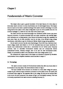
The matrix converter is a new topology of direct frequency converter. It can thus obtain a three phase system x k , y k , z k amplitude and frequency variable voltage from the fixed industrial grid ak , bk , ck . This is achieved by a matrix of nine powers switching connecting each input phase ak , bk , ck to each output phase x k , y k , z k . The matrix converter used in the present work consists of two identical three-phase matrix converters. The schematic diagram of the converter is shown in Figure 1. The matrix converters have components of power electronics bidirectional, which are carrying current symmetrically in both directions and blocking voltages of both polarities. In order to make a bidirectional opening and closing state semiconductor switching, we use the unidirectional power elements, therefore we have a choice of several topologies that fall into two basic categories: switches an element box diodes and switches to two elements being anti-parallel. As shown in Figure 2. [6] -[7] -[8].
International Journal of Research and Reviews in Computing Engineering ax1 bx1° cx1°
x1
ay1 by1° cy1°
y1
az1 bz1° ° cz1° °
z1
ax 2 bx 2° ° cx 2° °
x2
ay 2 by 2° cy 2°
y2
az 2 bz 2° ° cz 2° °
z2
° ° ° °
va1
° ° ° °
vb1 vc1
follows:
v xk Faxk Fbxk Fcxk v ak v yk Fayk Fbyk Fcyk vbk v zk Fazk Fbzk Fczk v ck DSIM
MASD E
w
° °
N
° °
° ° ° °
va 2 vb 2 vc 2
° °
N
Figure diagram matrix converter - DSIM Fig.1.1.Schematic Schéma de principe duof convertisseur matriciel - MASDE
i
°
°
°
i
°
b)
a)
2
Similarly for the current
iak Faxk Fayk Fazk i xk ibk Fbxk Fbyk Fbzk i yk i ck Fcxk Fcyk Fczk izk
through fictitious i
(2)
2.1. Order of matrix converter” k” The problem of controlling the matrix converter is to find the pulse sequences for the rolling average of the voltages at the output stages which are modulated sinusoidally. The amplitude and frequency of the fundamental wave of voltage should be variable. To achieve this, we use the command by the modulation vector (phasor space). The objective of this control strategy is to synthesize the output voltages from input voltages and input currents from the output currents [10]. The modulation vector for the matrix converter, describes a fictional equivalent circuit combining two stages, inverter stage and rectifier stage, which are linked by a voltage
° i
°
(1)
VDC in Figure 4.
°
v c)
Fig.II.2. Interrupteurs Figure 2.bidirectionnels Bidirectional switches a- Montage en émetteur communemitter a-mountable common b- Montage en collecteur commun b-mountable common collector c- Montage à pont de diode c-editing-Bridge d- Montage à deux transistorsDiode (IGBT)
d)
°
d-editing two transistors (IGBT)
In our study, we assume that each switch is modeled by a directional controllable switch at opening and closing state Figure 3. Tax1k TAX1k Rectifier stage
TAX2k Tax2k G
GAXk Gaxk
AXk Gaxk Fig.3.Figure Commutateur bidirectionnel équivalent. 3. Bidirectional switch equivalent.
The total number of bidirectional switches in the proposed matrix converter topology is nine for each matrix converter. With this number of switches a total combination of switching can be made in range 29=512. For the safe switching in the matrix converter; [9]. Input phases should never be circuited and the output phases should never be open circuited. Ensuring By following the two rules above, the number of possible combinations is reduced to 33 27 . In this case a vector of order 3 is sufficient to describe the switching states of the complete matrix for each converter k k 1,2 . Then the conversion matrix is given for the matrix converter as
Inverter stage
Figure.4.. Matrix converter model with intermediate circuit fictitious.
The scheme is based on the complex transformation vectors instantaneous output voltages and input currents. The three-phase system is transformed into two lines complex as follows:
2 j k 1 Vyk e j 2 / 3e j k 1 Vzk e j 4 / 3e j k 1 V0 k 3 Vxk e 2 j k 1 I bke j 2 / 3e j k 1 I ck e j 4 / 3e j k 1 I 0 k I ake 3 avec with k 1,2 , =30°
,
(3)
International Journal of Research and Reviews in Computing Engineering
The inverter stage consists of six switches the rectifier stage switches
V j 1
S 7 to S12 and also
S1 to S 6 , without any element of
d .V j 1
energy storage. The purpose of introducing the fictitious intermediate voltage is to decouple the input current control and output voltages control. The control of matrix converter is synthesized by the following modulation functions, using this approach the transfer matrix converter as follows:
Faxk Fayk
Fbxk Fbyk
T
S8 S S3 S5 S10 . 1 S 2 S 4 S 6 S11 S12 R
T
stage and R of the rectifier stage Orders for these converters are being shifted temporally to a period corresponding to the spatial offset between the two stars. 2.1.1. Inverter stage control The principle of space vector modulation (SVM), is to reconstruct the voltage vector Vref from eight voltage vectors, each vector corresponds to a combination of the switches of an inverter phase voltage, as shown in the following Figure 5. A reference voltage vector Vref is generally calculated and approximated over a period of modulation Te by an average voltage vector Vmoy. The latter is developed by applying the adjacent voltage vectors and zero vectorsV0 and V7.The Figure 6 .represents the case where the reference vector lies in the sector (1). The application time of adjacent vectors is given as follows:
V j .T j V j 1 .T j 1 Tn .V0 Te.Vs * * Vs sin( 3 v ) T . .Te, j V sin DC 3 T / 2 T T Te T T 0 7 j j 1 n
Vs
Tj
d .V j
Te
Vj
Vj
the system input voltage. Two vectors I and
I will be
constructed for the rectifier stage with duty cycles d and
d which are calculated the same way as d and d by :
d mi sin i 3 i d m sin i d 1 d d 0 where
i
(6)
d 0 is the duty cycle of zero current vector.
: terms of reference current vector in the current sector
or is it Figure 7. mi : Is the modulation index input current is often set to unit. β
I3 (B, C)
3
I2 (A, C)
2
*
T j 1
V3 0,1,0
(5)
1
α I5 (C, A)
5
6
I1 (A, B)
I6 (C, B)
V2 1,1,0
Figure 7. Possible switching states.
II Vs I
III
V4 0,1,1 V 0,0,0 0
(A,B)
*
V1 1,0,0
V7 1,1,1
VI
IV
d .I
Ie
V
V5 0,0,1
*
v
I4 (B, A)
Vs sin( v ) . .Te VDC sin 3
V j 1
2.1.2. Rectifier stage control In the same way as the inverter stage, a current space vector is synthesized from the current input, synchronized to
(4)
I is the transfer matrix of the inverter
Te
Figure.6. Location of reference vector.
I
Where the matrix
T j 1
, is defined for the
Fcxk S 7 Fcyk S 9
Fazk Fbzk Fczk
3
V6 1,0,1
Figure 5. Possible switching states.
Fig.6. états de commutations possibles.
θi
(C,B)
d .I Figure 8. Location of reference vector.
International Journal of Research and Reviews in Computing Engineering
4
Begin
Thus, the switching sequences chosen for the rectifier are:
I I I 0 I I 2.1.3. Matrix converter control To ensure the control of matrix converter, the two modulation strategies must be now combined to generate the switching sequences. Both two-way vector sequences become nine sequences defined as follows:
Find v angle of voltage
Find i angle of voltage
Find the area of phasor of voltage
Find the area of phasor of current
0
Find the zéro phsor of voltage
The duty cycle of each sequence is determined by the product of the corresponding duty cycles as follows:
d d d d
Calculate the duty cycle d0 of current Equation (5)
d .d d .d d .d
(7)
Calculate the duty cycle d0 of current Equation (6)
Select the two phsors(α,β)
d .d
(8)
In the order of switching sequences, and En 4equence comme exemple le vecteur de tension de sortie et celui du courant d’entrée dans le secteur 1 on aura les 4equences de commutation suivants : Taking as example the vector of output voltage and the input current in sector 1 we have the following switching sequence: CBC-ABA-ABB-CBB-BBB-CBB-ABB-ABA-CBC. Figure 9 shows how to build the switching table for the whole situations of output voltage and input current.
Generate control signals
Select the two phsors(,) Calculate the duty cycle (,) Equation (6)
Calculate the duty cycle (α, β) Equation (5)
Where the duty cycle of zero vectors is calculated by:
d 0 1 d d d d
Find the zéro phsor of current
Calculate the duty mixed cycle Equation (7)
Order of success
Figure 9. how to generate control signals
3.
Numerical simulation
The simulation method of vector modulation matrix converters directly feeding the double star induction machine has been done on MATLAB / SIMULINK. The simulation
f s 50Hz , The rms value of the voltage: V 275V , in order to get 220V output of converters and Cr 14 N .m .
parameters are:
3.1. Performance of vector modulation strategy For this control strategy and for a period of switching converters 2 KHz, it simulates the des phases x k (k=1, 2) (tension par rapport au neutre de la machine asynchrone à double étoile) délivrée par le convertisseur matriciel k ainsi leur spectres d'harmoniques. phases voltages x k (k = 1, 2) (voltage relative to neutral machine asynchronous dual star) issued by the converter matrix k and their harmonic spectra. The simulation results obtained are shown in figures Figure 10, the graphs represent the aspect of voltage VX1 and VX2 output matrix converters and their spectra. We can see that the waveform of voltages is acceptable despite the emergence of a few harmonics author of the switching frequency (2kHz).
5
Amplitude of harmonics
International Journal of Research and Reviews in Computing Engineering
Time (s) Amplitude of harmonics
Rang of harmonics
Time (s)
Rang of harmonics Figure 10. Characteristics of voltage Vx1 and VX2 output matrix converters controlled by the modulation vector
Time (s) Current ix1(A)
Current ix1(A)
Time (s)
Time (s)
Time (s) Current ix12(A)
Current ix2(A)
Time (s)
The graphs in Figure 11 and Figure 12 illustrate the performance of double star induction machine fed by matrix converters controlled by the technique of modulation vector. The establishment of speed is fast, the motor is not loaded. The speed attained is closed to synchronism, at t = 1.2s, a resistive torque of 14 Nm is applied and the speed decreases. The electromagnetic torque gets the load torque after t=0.8s The current absorbed by the double star induction machine are almost sinusoidal. 3.3. Operation of matrix converter in the four quadrants In this section, we will verify the operation in four quadrants of the association matrix converter double star induction machine controlled by the vector modulation strategy. For this, we interchange between the reference
Speed (rd/s)
Torque (N.m)
3.2. Performance of the association matrix converter DSIM It directly feeds the induction machine double star by matrix converters. The simulation departs for startup vacuum after the steady state was established; we apply a torque load to the machine. The simulation results shown in the Figure 11 represent the following quantities: The electromagnetic torque. The stator current phases x1 and x2 of the DSIM. The speed of DSIM.
Figure 12. Input phase current ix1 and ix2 with their spectra.
Time (s)
Figure 11. Performance of the association matrix converter double star induction machine controlled by the vector modulation strategy.
voltages: ( v y1 and v z1réf ) and ( v y 2 and v z 2 réf ) at réf réf time t (t = 2 for example) the steady state. Simulationsde la phase Y1 et phases’ voltage of Y1 de la phase Y2 délivrées par les convertisseurs matriciels 1 et 2 et leurs spectres d'harmoniques pour la fréquence f s =5and Y2 issued by matrix converters 1 and 2 and their harmonic spectra for the frequency f s = 50 Hz Les résultats trouvés sont exposés sur les Figure 13. According to Figure 13, spectra of harmonic voltages are almost the same before and after the reversal of rotation of the double star induction machine. Hence the operation in all four quadrants is possible of the association matrix converter double star induction machine.
International Journal of Research and Reviews in Computing Engineering
6
P. NIELSEN, F. BLAABJERG and J.K. PEDERSEN, ‘’ New protection issues of a matrix converter: design considerations for adjustable-speed drives’’, IEEE Trans. On industry Applications, Vol. 35, N°5, pp.1150-1161, September, October 1999. [7] L. GONTHER, T. LEQUEN et J.C. ANCEAU, ‘’ Application de la démarche d’intégration fonctionnelle : intégration d’un interrupteur Mos à tenue inverse en tension et définition d’une cellule de commutation pour le cas alternatif’’, EPF’98, Belfort, France, pp.1520,1998. [8] P.Wheeler .J.cleer.Lee .Empringham, M.Apap .and M.Bland « Matrixe converter » power engineering journal december 2002, in IEEE. [9] K. Ghedamsi « Contribution à la modélisation et la commande d’un convertisseur direct de fréquence application à la conduite de la machine synchrone ». Thèse doctorat ENP année 2008. [10] Takashi Yoshinaga, Tomoaki Terunum,Kouki Mateuse « Basic Characteristic of Parallel- Connected Dual Induction Motor Drives with Matrix Converter » in IEEE 2008 Dept. of Electrical and Electronic Engineering Meiji University. [11] H. Amimeur ‘’ Contribution à la commande d’une machine asynchrone double étoile par mode de glissement » mémoire de magister université de Batna 2008. [6]
Figure.13. characteristics of VY1 and Vy2 output voltage matrix converters controlled by the vector modulation strategy before and after the reversal of rotation.
4.
Conclusion
This article has been devoted to the study by numerical simulation of matrix converter controlled by the modulation vector, feeding a double star induction machine. We can say that the matrix converter operates in the four quadrants. The performances obtained show that the proposed control technology is distinguished by comparison with indirect converters (AC-DC-AC) by the reversibility of the converter. We can confirm that the benefits of using this type of converter are numerous; we include among other things, increasing the power, reduction of oscillations of the switching frequency of power switches and improved forms of output quantities.
Appendix Double star induction machine parameters [11] Pn 4.2kw , Rs 3.72 Rr 2.12 ,
Ls1 Ls 2 0.022H Lr 0.006H Lm 0.3672H , ,
,
p 1,
J 0.0625Kg.m F 0.001N.m.s / rad , V 220V , 2
,
I n 4.5 A
References [1]
[2]
[3]
[4]
[5]
I.Messaïf, E.M. Berkouk et N. Saadia,‘’Contrôle Direct du Couple d’une Machine Asynchrone Alimentée par un onduleur à 3 Niveaux de Tension’’4th intrnational Conference on Electrical Engineering 07-08 November 2006. BatnaUniversity (Algéria). E. Levi, R. Bojoi, F. Profumo, H.A. Toliyat and S.Williamson ‘’ Multiphase induction motor drives – a technology status review’’ IET Electr.power Appl.,2007,1, (4), pp. 489-516. J.K.KANG, H. HARA, A. HAVA, E. YAMAMOTO, E. WATANABL and T. KUNE, ‘’ The matrix converter drive performance under abnormal input voltage conditions”, in IEEE Trans. On power Electronics. Vol.17, N°5, pp.721-723, September 2002. SK. Moin Ahmed, Haitham Abu-Rub, Atif Iqbal, Mohd. Rizwan Khan ‘’ Space vector PWM technique for a novel three-to- five phase matrix converter” IEEE, 2010. Takashi Yoshinaga, Tomaoki, Kouki Matsuse ‘’Basic characteristic of parallel- connected dual induction motor drives with matrix converter” IEEE, 2008.
Ahmed AZIB: PhD student in electrical engineering at the University of Bejaia, Algeria. He has had a Bachelor in June 2001, Engineer in electrical engineering in June 2006 and master in electrical option: electro-energetic at the University of Bejaia In July 2009. His work field includes the study and control of static converters (power electronics) and their association with electrical machines. Farid TAZERART: PhD student in electrical engineering at the University of Bejaia, Algeria. He has had a Bachelor in June 2001, Engineer in electrical engineering in June 2006 option: electromichanical and master in electrical option: Industrial –Electric at the University of Biskra In July 2009. His work field includes the study and control of static converters (power electronics) and their association with electrical machines. Brahim METIDJI: was born in Bouira, Algeria . He received the M.S degree in electrical engineering from the University of Bejaia, Algeria. Now he is PhD student in electrical engineering at the University of Bejaia, Algeria. His research interests are in variable-speed ac motor drives,in particular, matrix converter.
Nabil TAIB (1977), received his Engineering Degree and Master Degree on Electrical Control Systems in 2001 and 2004 respectively from the University of Bejaia (Algeria). Since 2005 he is preaparing his Doctoral thesis at the same University where the focused research is on the matrix converters and their applications. From 2009, he is assistant master in the Electrical Engineering Department at the University A. Mira of Bejaia (Algeria). He is an Editor Board Member in the International Journal of Computer Science and Emerging Technologies (IJCSET). He is interrested now, by the applications of the matrix converters on the renewable energy systems. Toufik REKIOUA (1962), received his Egineering Degree from the Polytechnical National School (Algeria) and earned the Doctoral Degree from I.N.P.L of Nancy (France) in 1991. Since 1992, he is assistant professor at the Electrical Engineering department-University A. Mira of Bejaia (Algeria). His research activities have been devoted to several topics: control of electrical drives, modeling and control of A.C machines, the renewable energy systems.