Method for Method Configuration into the tool support MC Sandbox. The func- tionality in MC Sandbox emphasizes reusable method assets and MC based on.
MC Sandbox – Tool Support for Method Configuration Fredrik Karlsson1 and Kai Wistrand1 1
Örebro University, MELAB, Dept. of Informatics (ESI), SE-701 82 Örebro, Sweden {fkn, kwd}@esi.oru.se www.oru.se/esi/melab
Abstract. Method configuration (MC) has been presented as a particular kind of method engineering (ME). ME in general is often a tedious and time consuming task and method configuration is no exception. Consequently, tool support is often required. In this paper we present an operationalization of the Method for Method Configuration into the tool support MC Sandbox. The functionality in MC Sandbox emphasizes reusable method assets and MC based on methods’ rationale. The latter is usually not considered as an explicit focal area within ME. Furthermore, we present the experiences from the first workshop where the MC Sandbox has been successfully used during configuration work, and the repercussions it has on the design of the tool and the meta-method.
1 Introduction Situational methods [1] or methods-in-action [2] are terms that are commonly used today. As stated by Fitzgerald et al. [3] ‘it is now widely accepted that methods should be tailored to the actual needs of the development context’, while ‘there is very little by way of practical guidance to inform developers as to what steps of the method to modify or omit.’ Odell [4] and Ralyté et al. [5] have surveyed the range of existing research in the field of Method Engineering (ME) and divided it into different categories. From these articles one can conclude that the modular method construction seems to be the main track. However, in days where ‘off-the-shelf’ methods, such as the Rational Unified Process (RUP) or Microsoft Solution Framework (MSF), increase in popularity a different point of departure is often needed. In these situations it is a question of tailoring one single method. Ralyté et al. [5] identify an extension strategy for methods and discuss a cancellation operator. But whether it should be treated as part of the extension strategy or not, is unclear. A combination of the cancellation and extension operators has been proposed, labeled method configuration (MC) [6]. Accordingly, MC is a particular form of ME defined as: Definition 1. Method Configuration is the planned and systematic adaptation of a specific method generating reusable method assets.
MC, as well as ME in general, is often a complex and tedious tasks. Accordingly, it is time and resource consuming and tool support is often a necessity. If computerized tool support can be regarded as extensions of methods it is natural to conclude that modular method constructing has been the main theme for Computer Aided Method Engineering (CAME) as well. According to Rossi [7] CAME tools consist two main parts: one part where the method is described and a second part where a CASE tool is specified, a tool that supports the modeled method. The attention has been given to conceptual issues, which is natural when specifying Computer Aided Systems Engineering (CASE) tools. It is apparent when evaluating both research and commercial CAME products [see e.g. 1, 7, 8, 9, 10]. However, method construction and integration is considered peripheral to MC, whereas method tailoring is essential. In this paper we present a computerized tool, the MC Sandbox, for MC based on methods’ rationale, which is usually not considered as an explicit focal area within method engineering [11, 12]. The tool is an operationalization of the Method for Method Configuration (MMC) containing underpinning principles for MC [13]. The tool is a prototype and we report on a study where this tool has been used during configuration of the MSF. Subsequently, in this paper we report on an initial test of whether or not explicit focus of methods’ rationale is valuable during method configuration. If such functionality is valuable it could be provided in CAME tools that include CASE generation. This paper is organized in seven sections. In the following section we discuss the research method adopted during this study. Section three describes the theoretical base for the tool, i.e. the underpinning principles of the MMC. We devote the fourth section to a description of the MC Sandbox. The fifth section of the paper contains the case description, which is followed by a discussion about the lessons learned. We end the paper with a short conclusion.
2 Research method The grounding of methods and tools is often founded in three intertwined processes: external theoretical, internal, and empirical grounding. Goldkuhl [14] describes these processes as strategies for grounding of action knowledge. The research reported in this paper put the empirical grounding in the foreground. However, we do not mean that it is the most important grounding process or that we do not pay regard to the other two processes. Development of the MMC and MC Sandbox is part of a larger research project, the FlexPro project, that aim to explicate method rationale as a focal area within method configuration [15]. In this larger context we work with all three grounding processes and use a collaborative practice research strategy [16]. Through this strategy, cases are chosen with different combinations of intervention and observation. Thus when the academic and the industrial sphere meet, the grounding processes are strengthened by the possibility to involve competent practitioners in the design efforts of the MMC and the MC Sandbox. In addition, it facilitates management of the dual processes – the research and the problem solving processes – that are usually present during empirical grounding.
The industrial partner for this specific study was Precio Systemutveckling AB (Precio). They use the MSF as their day-to-day method during projects. Hence they tailor a specific method, which we term base method, based on the needs of each project, which match the situation sketched in the introduction. We report from a rather small project. The choice was deliberate, since a smaller project is easier to access when considering an initial test of the tool. Furthermore, small projects often demand lightweight methods and therefore require tailoring of methods. The disadvantage is the low complexity in the situation; complex projects might put other demands on both the MMC and the tool. Thus, in the larger context we have to complement with additional, more complex, cases.
3 Theoretical Base The core of MMC consists of three major concepts to facilitate the reusable tailoring of a base method, on the basis of methods’ rationale: the method component, the configuration package and the configuration template. The smallest meaningful part of a method is the method component. It is used together with the canceling and extension operators to tailor methods. We define the concept as: Definition 2. A Method Component is a self-contained part of a method, expressing the transformation of one or several artifacts into a defined target artifact and the rationale for such a transformation The basic idea of the MMC is to the use the concept of characteristics [17] to narrow the focus on a delimited part of a development situation, that is an abstraction of projects. A characteristic is a delimited part of a development situation, focusing on a certain problem or aspect which the method configuration aims to solve or handle. The delimited configuration is named configuration package and is one possible configuration of method components for a specific characteristic. Definition 3. A Configuration Package is a method configuration of the base method suitable for a characteristic’s value. In order to facilitate classification of method components the MMC has a classification schema. The classes implemented in the tool are ‘Perform As Is’, ‘Omit’, ‘Added’ and ‘Exchanges’. The analysis is based on the method component’s rationale and the possibilities to reach rationality resonance [18] between the method and project members in a development situation. In a situation where parts of the base method’s rationale are considered superfluous components are classified ‘Omit’. For example, when conducting requirements engineering in a simple problem domain, a glossary component might not contribute to the project. Consequently, it could be suppressed. A component is classified ‘Perform As Is’ if its rationale is relevant with regard to the characteristic. In cases where the base method lacks possibility to reach rationality resonance it has to be extended with parts from additional methods.
Method components can be added as complements and would be classified ‘Added’. Finally, we have the exchange situation. Project members could use a method component found in the base method, but the possibility to reach rationality resonance would increase through the use of other components. In such situations an exchange of components could be fruitful, and the new component is classified ‘Exchanges’. Few, if any, development situations involve only a single characteristic. Hence, one single configuration package will in most cases not be sufficient for turning a base method into a situational method. Therefore, we introduce the configuration template as a collection of configuration packages. Definition 4. A Configuration Template is a combination of Configuration Packages, for a set of recurrent project characteristics. A configuration template is a pre-configuration for a development situation with certain characteristics. Consequently, a configuration template is a selection of configuration packages. For example, consider a situation where the users are responsible for the requirements engineering through development of End User Computing (EUC) [19] applications. The end users could structure the requirements through the use of a spreadsheet application. Furthermore, since we discuss EUC it is natural to consider a development situation where the solution is anchored in the business through continuous business modeling or awareness during daily work. In this case we would have two characteristics that shape our configuration template, and the selection of configuration packages: ‘Requirements Using EUC’ and ‘Known Business Objectives’. Since the selected configuration packages could overlap, we have to keep track of the combination. In a configuration template each classification could either be derived from a configuration package associated with the configuration template, or it can be a reclassification caused by conflicting configuration packages. Finally, configuration templates are turned into situational methods. Each project is characterized using the range of characteristics that has previously been elicited. The resulting profile is matched with a development situation and its configuration template. Minor changes could be made to the pre-configuration based on the specific project.
4 MC Sandbox In the theoretical discussion above we discern three core procedures in the MMC and two supportive procedures. The latter are procedures for elaborating method components and converting an existing base method into an editable version in the MC Sandbox. The three core procedures support direct MC work, which is defining configuration packages, configuration templates and situational methods. Due to the limitation of this paper we focus on the functionality where method components and configuration packages are defined. The selection is based on where in MC Sandbox’s functionality methods’ rationale is emphasized.
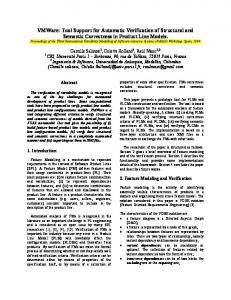
4.1 Define Method Component The basis for creating method components is the base method and additional methods. A method component has two basic views, the internal and the external view [20]. The external view hides content parts of the components that are not necessary during MC. It hides details through the use of an interface containing the component’s overall goal, prerequisites and deliverable. The method engineers use the internal view during construction of the component and method users use it when they need to look more in detail on a component. A method component contains five different method elements [20]: concept, notation, artifact, prescribed action and actor role. Each method element has one or more goals associated to express each element’s rationale. An overall goal is presented in the method component’s interface together with the prerequisites and deliverable of the method component. Prerequisites are artifacts used in the method component, and deliverable is the resulting artifact. Accordingly, method components are connected through the prerequisites and deliverables. Tree Browser
Method Component’s Rationale
Method Element Inspector
Fig. 1. Defining a method component
Fig. 1 presents the method component’s internal view as implemented in the MC Sandbox. The graphical user interface (GUI) is divided into three major parts. To the left we find a tree browser showing the method component’s method elements. Each method element belongs to one of the categories discussed above. However, we have placed the notation together with the concept, since the relationship between these two classes is strong. The midsection of the GUI contains the modeling view of the method component’s rationale. Each box represents a goal and arrows indicate goal achievements between method elements. At the top of the hierarchy we find the method component’s overall goal. The right most part of the screen shot illustrates the method element inspector, containing information about the method element that is selected in the tree browser. In this case it contains information about an artifact and
whether or not it is a prerequisite. The Vision/Scope artifact is not a prerequisite (the artifact is not defined as input) for the method component, and consequently it must be a deliverable. 4.3 Define Configuration Package The basis for a configuration package is the base method. Each configuration package follows the structure of the base method. It means that changes in the base method have repercussions in every configuration package. For example, if we add a method component to the base method, it is added to every configuration package. Hence the method engineer will work with the external view of method components when defining a configuration package, similar to the view used for defining the base method. The right part of the GUI in Fig. 2 contains a list of available method components that are not part of the base method. The right part of the GUI contains the base method tailored for a specific characteristic’s value. Each method component is presented using the external view, and is represented by a rectangle. The arrows between the method components show the flow between the components, which can be one-way as well as two-way. Different colors show a method component’s classification. When the method engineer opens a new configuration package every method component in the package is initially classified ‘Not Applicable’. These components are outside the characteristic’s scope. Such components are not considered in a future combination into a configuration template and cannot cause conflicts between overlapping configuration packages. Thus, the method engineer has to make an active choice to place a method component within the characteristic’s scope and this choice is made with the classification tool. It is found in the vertical tool bar in Fig. 2, highlighted with a circle. The method engineer uses a configuration tool to click on a method component and choose the classification from a popup menu, which is illustrated beneath the Vision/Scope component. The choices available are ‘Perform As Is’, ‘Omit’, and ‘Exchanges’. The classification ‘Added’ is not possible to reach from the popup menu, since it requires that a complementing component has been selected in the method component list and added to the graph. When it is done it receives ‘Added ‘. Furthermore, ‘Exchanges’ can only be applied on components that have been added to the graph, since the purpose is to exchange a method component prescribed by the base method.
Method Component Status
Available Method Components/ Method Framework
Modelling Views
Fig. 2. Defining a configuration package
The selected method component’s current status is presented in the status tab. Here we find information about the component, and it is presented from an external view. The component’s interface in Fig. 2 contains information about the component’s rationale (selected rationale), current classification, prerequisite (input) and output. Furthermore, the method engineer can be provided arguments for the current classification (classification rationale). Accordingly, the tool facilitates tracking of configuration decisions and its arguments. The latter are important when returning to earlier configurations and for sharing knowledge between method engineers. 4.4 Define Configuration Template A configuration template is a selection of configuration packages. It is based on the totality of characteristic of the development situation that the template is designed for and a profile for the development situation is created. Only one configuration packages is possible, but not necessary, to chose per characteristic. If a characteristic is not relevant, it can be left out when selecting configuration packages. When the selections have been made the method engineer builds the configuration template. If conflicts arise when building, the tool lists them together with a reason. The method engineer then has to solve these conflicts by giving priority to a configuration package. For example one configuration package might classify the Vision/Scope component in Fig. 2 as ‘Omit’ while a second package classifies it ‘Perform As Is’. When the method engineer has solved the conflicts the configuration template could be rebuilt. The result is a combination of classifications from the aggregated configuration packages and the manual reclassifications that have been made. Further adjustments can be made if the method engineer discovers that the combination for example leaves a method component without input. The method engineer can use the same classification tool as for configuration packages to solve
such problems. Furthermore, the configuration rationale for each component has been transferred from the selected configuration packages to the configuration template in order to make the configuration process transparent.
5 The Precio Case The empirical example comes from a project at Precio. The short introduction below is based on the initial interview that was conducted before the actual configuration work. The interview served as background information for one of the authors when conducting the method configuration together with the project team. The project’s purpose was to build an extension to an existing system that supports management of projects. The new module was supposed to deliver reports from the existing system. Precio had built the existing system and one of the consultants had been working together with the customer on that system. Accordingly, the knowledge both about the system and the customer’s business processes were rather well known. The aim of the project on a business layer was to improve the customer’s information and co-ordination of projects. The existing report generator only supported a small user group. Through the new module this user group could be extended and in the end incorporate about 70 users. The project lasted over six calendar months and involved two systems engineers from Precio and one systems engineer from the customer. The customer was supposed to continue the maintenance of this module once it had been developed. Consequently, the knowledge transfer between the consultants and the customer was important. However, the small size of the project team facilitated a need for a rather informal communication structure. One of the more conspicuous characteristics during the initial interview was the unclear picture of requirements. The users did not seem to have a clear picture of their needs, or at least not how to make them explicit. Therefore, the project team proposed that requirements engineering should be conducted in workshops where prototypes were discussed. Hence, more emphasis should be put on prototypes than use case descriptions. The project team rated this project as a low risk project. One obvious risk was the technology. It only existed in a beta version when the project started and the customer did not accept a deployment of a beta version into their environment. Thus the prototypes had to be built on an evolving technology, which could be changed during the project. Furthermore, the customer had an explicit requirement that the solution should use features in the Microsoft BizTalk 2004, features that had not been used before by the consultants. This configuration was the first configuration done at Precio. We had no characteristics or configuration packages to start with. It meant that the project was synonymous to a development situation in this case. Hence the possibilities of reuse were not present, if we demarcate ourselves to this organization. However, inspiration was taken from earlier configuration work in other organizations [21]. Six characteristics were chiseled: Difficulties to make requirements explicit, Type of risk, The project team, Type of deployment, Type of implementation, and Type of testing. The charac-
teristics project team, and type of testing can also be found in Karlsson [21], however the configuration packages were, in that case, built on the Rational Unified Process [22]. The characteristic ‘Difficulties to make requirements explicit’ focuses the problems the team felt while the eliciting requirements. A configuration package was created that tailored the MSF for handling these difficulties. For example, the Usage Scenarios in the MSF were omitted together with the Functional Specification. Instead, the project team wanted to emphasize the Prototype component as a way to gather requirements. A configuration package was also created to address the project’s type of risk. The most interesting classifications in this package is the low need of a risk assessment, since they were already analyzed before the project started, and the need to address the technical issues. Concretely, it meant that the Risk Template Tool was omitted and the Proof-of-Concept was considered important to perform. Furthermore, the project members expressed that the Risk Assessment Tool should be used, but the use should be informal. It meant that the prescribed actions of the method component should be performed but the artifact should not be produced. This argument was not a clear-cut argument for the risk discussion; rather such an informal use was possible in this small project team. The small project team was another characteristic, and we created a configuration package for small teams. In this configuration package we addressed method components such as the Project Structure, the Communication Plan, and the Master Project Plan. For this part of the development situation the informal communication played a central role in the discussion. The rationale of the Communication Plan was considered superfluous and it was omitted from the base method. On the other hand, the Master Project Plan was necessary for communication with different stakeholders outside the project team, hence it was classified ‘Perform As Is’. The fourth characteristic was ‘Type of deployment’. Here the discussion centered the knowledge about the target environment and the method components in the MSF that deal with deployment. Since Precio had built the existing system they had knowledge about that system. However the project team still felt a need to perform the Current State Infrastructure component in order to get a complete picture of the current state. For the two final characteristics we created configuration packages to tailor the base method for source code implementation and manual testing with users. The purpose of the former package was to distinguish from a development situation where no information system should be built, that is suppressing these parts from the method. The latter package targets how the requirements have been satisfactorily implemented. In this case no automated testing tools could be used since it is the content and structure of each report that are important.
6 Lessoned learned and repercussion on the design The Precio case showed that the MC Sandbox’s functionality contributed with a valuable focus during the configuration work. The consultants found value in the basic
idea of reuse, since it reduces the time needed to discuss details about projects and their implications on the base method. The use of the method component concept was a natural starting point for the configuration work. Furthermore, the project members agreed that focusing on the method’s product model, that it is the method components’ deliverables, is in line with how they normally chose parts from a method; where the deliverable’s rationale is of decisive importance for their choice. Accordingly, the possibilities to use the method components’ external view to focus a selected method component’s rationale were considered useful functions. However, during this workshop a discussion arose about the number of goals a method component could express in its interface. The project members wanted more precise goals to illustrate what a component’s deliverable could be used for later on in the method. Of course, a method component could fill a multipurpose during a project but making this explicit means implementing a rigid view on methods and delimiting the possibilities to use a component in new combinations than prescribed by these goals. Therefore, we do not change the design. During this workshop certain GUI-aspect were discussed. The external view used during modeling of configuration packages or templates was initially not considered easy-to-grasp. The problem with the point-and-click GUI in Fig. 2 is the relationships between method components. The graph tends to get cluttered. Furthermore, the complexity of this view increases with the complexity of the method. A GUI using a table structure was discussed as either as a complement or as a replacement. A mockup is presented in Fig. 3. Each method component is expressed as a row, with the prerequisites expressed below in grey text. The classification is performed with list box-functions, and the rationale is expressed in the rightmost column. The advantage of this GUI is the possibility to hide prerequisites using the plus/minus sign in the leftmost column, which reduces the complexity.
Fig. 3. Mock-up Interface
On several occasions during the configuration workshop the project members expressed a need for an informal classification of components. As explained above the prescribed actions were considered essential but not the deliverable. The MC Sandbox as well as the current version of the MMC lacks such a value when classifying components. It has been part of the classification schema in earlier versions of the MMC when working with method fragments [6]. When introducing the notion of method components it was suppressed to simplify the number of possible classifications. Possibly, a reintroduction has to be considered.
7 Conclusions In this paper the MC Sandbox has been presented as an operationalization of the Method for Method Configuration (MMC). We have presented how the theoretical base of MMC is present in a primary prototype, facilitating method configuration (MC) based on methods’ rationale. MC according to MMC is performed using three main concepts: method component, configuration package, and configuration template. The method component concept is used as the smallest meaningful part of a method and a concept that is the carrier of methods’ rationale. The two latter concepts are concepts that emphasizes reuse through creating pre-configurations based on a development situation’s characteristics. An empirical example has been presented to illustrate the benefits of focusing the method components’ rationale during configuration work, which primarily concerns suppressions of method parts. We have received indications on flaws as well as useful functions in MC Sandbox. Furthermore, we reported on reuse of characteristics between organizations. The content of the belonging configuration packages was not possible to reuse in this case, since they had different methods as starting points for their method configurations. However, further testing is needed in order to gather more experiences on both the reuse and the methods’ rationale issues. The former requires a larger range of projects within the same organization or at least a method configuration based on the same method.
Acknowledgement The Swedish Knowledge Foundation (KK-stiftelsen), Precio and Örebro University the Department of Informatics (ESI) have financially supported this work.
References 1. Harmsen, A.F.: Situational Method Engineering. Moret Ernst & Young Management Consultants, Utrecht, The Netherlands (1997) 2. Fitzgerald, B., N.L. Russo, and E. Stolterman: Information Systems Development - Methods in Action. McGraw-Hill, London (2002) 3. Fitzgerald, B., N.L. Russo, and T. O'Kane: Software Development Method Tailoring at Motorola. Vol. 46(4) (2003) 65-70 4. Odell, J.J.: A primer to method engineering. In. Method Engineering: Principles of method construction and tool support (IFIP TC8, WG8.7/8.2 Working conference on method engineering), Atlanta, USA., (1996) 5. Ralyté, J., R. Deneckère, and C. Rolland: Towards a Generic Model for Situational Method Engineering. In M.M. Johann Eder. Advanced Information Systems Engineering, 15th International Conference, CAiSE 2003, Klagenfurt, Austria, June 16-18, 2003, (2003) 6. Karlsson, F., P.J. Ågerfalk, and A. Hjalmarsson: Process Configuration with Development Tracks and Generic Project Types. In. Proceedings of the 6th CAiSE/IFIP8.1 International
Workshop on Evaluation of Modelling Methods in Systems Analysis and Design (EMMSAD’01), (2001) 7. Rossi, M.: Advanced Computer Support for Method Engineering: Implementation of CAME Environment in MetaEdit+. University of Jyväskylä, Jyväskylä, Finland (1998) 8. Dahanayake, A.: Computer-aided method engineering : designing CASE repositories for the 21st century. Idea Group Publishing, London, UK (2000) 9. Kelly, S.: Towards a Comprehensive MetaCASE and CAME Environment - Conceptual, Architectural, Functional and Usability Advances in MetaEdit+. In. University of Jyväskylä, Jyväskylä, (1997) 10. Rational: Rational Process Workbench. Rational Software, (2002) 11. Ågerfalk, P.J. and K. Åhlgren: Modelling the rationale of methods. In M. Khosrowpour. Managing Information Technology Resources in Organizations in the Next Millennium, IDEA Group Publishing, Hershey, PA, (1999) 12. Rossi, M., et al.: Method Rationale in Method Engineering. In. Proceedings of the 33rd Hawaii International Conference on System Sciences (HICSS-33), IEEE Computer Society Press, (2000) 13. Karlsson, F.: Meta-method for Method Configuration: A Rational Unified Process Case. Dept. of Computer and Information Science, Linköping University, Linköping (2002) 14. Goldkuhl, G.: The grounding of usable knowledge: An inquiry in the epistemology of action knowledge. Linköping University, CMTO Research Papers 1999:03, Linköping, Sweden (1999) 15. Ågerfalk, P.J., et al.: Flexible Processes and Method Configuration: Outline of a Joint Industry-Academia Research Project. In. Proceedings of the 5th International Conference on Enterprise Information Systems (ICEIS 2003), (2003) 16. Mathiassen, L.: Collaborative Practice Research. In.15, Information Technology & People, (2002) 17. van Slooten, K. and B. Hodes: Characterizing IS development projects. In S. Brinkkemper, K. Lyytinen, and R. Welke. Method Engineering: Principles of method construction and tool support, Chapman & Hall, (1996) 18. Russo, N.L. and E. Stolterman: Exploring the assumptions underlying information systems methodologies: their impact on past, present and future ISM research. Information Technology & People, Vol. 13(4) (2000) 313–327 19. Avdic, A.: Användare och utvecklare: om anveckling med kalkylprogram. Deptartment of Computer and Information Science, Linköping University, Linköping, Sweden (1999) 20. Wistrand, K. and F. Karlsson. Method Components - Rationale Revealed. in The 16th International Conference on Advanced Information Systems Engineering (CAiSE 2004). 2004. Riga, Latvia. 21. Karlsson, F. On The Empirical Grounding of Meta-Method for Method Configuration The Personnel System. in PromoteIT 2003. 2003. Visby, Sweden. 22. Kruchten, P.: The rational unified process: an introduction. Addison-Wesley object technology series. Addison-Wesley, Reading, MA (1999)