Email: (hzhu | ibayley)@brookes.ac.uk. 2. Dept. of Computer Science, ... order logic, and the design patterns are formally specified in the same language. ..... the translated specification of Template Method pattern can be deduced from the ...
Tool Support for Design Pattern Recognition at Model Level Hong Zhu1 , Ian Bayley1 , Lijun Shan2 and Richard Amphlett1 School of Technology, Oxford Brookes University, Oxford OX33 1HX, UK Email: (hzhu | ibayley)@brookes.ac.uk 2 Dept. of Computer Science, National University of Defense Technology, Changsha, China 1
Abstract Given the rapid rise of model-driven software development methodologies, it is highly desirable that tools be developed to support the use of design patterns in this context. This paper presents such a tool, called LAMBDES-DP, with UML diagrams as the software design models. Its theoretical foundation is a descriptive semantics of UML in first order logic, and the design patterns are formally specified in the same language. The tool uses the LAMBDES system to translate the UML diagrams into their descriptive semantics and invokes the theorem prover SPASS to decide whether the design conforms to a pattern. Our experiments show that our tool has significantly lower rates of false positive and false negative errors compared with existing tools.
1 Motivation and Related Work Software design patterns are frequently used to share design expertise. They document solutions to commonly occurring design problems. It is widely recognized that their proper use can improve software quality and development productivity [29]. Software tools have been proposed that could spot the use of a pattern within a software system and/or check if a pattern is applied correctly. The prototype tool LAMBDES-DP presented in this paper is distinctive for two reasons. First, it facilitates model-driven development by working at the design level rather than code level. Secondly, it is based on a formalism that has been shown to be applicable to all 23 Gang of Four (GoF) patterns in [10]. Code-level tool support has been much reported [6], with examples including HEDGEHOG [5], FUJABA [24] and PINOT [25], but they all have relatively high error rates. As suggested in [13], this is probably because the level of abstraction is too low. Variations in implementation cannot be expressed systematically, for example, and important dynamic behaviours cannot be determined statically from the code alone. Kim et al. have advanced two separate approaches
to design-level tool support, both based on the role-based metamodelling language RBML [13] for specifying patterns. In [14], they translate RBML into a query on a Prolog database representing the UML model, but without explaining how to translate either language into Prolog. In [15, 16], they report a plug-in called RBMLCC for IBM Rational Rose but then apply it to only 7 of the 23 GoF patterns. Precision is essential for any tool, but the semantics of UML is lacking in this respect. So too is the usual presentation of design patterns: an informal combination of English, to explain basic principles, together with semigeneral UML diagrams and code examples, by way of illustration. So much work has gone into formal alternatives. Examples include the Design Pattern Modeling Language of Mapelsden et al. [22], the graphical language LePUS of Eden [7, 8], the use of predicate logic and temporal logic by Taibi [27, 28] and Mikkonen [23], the extension of the UML meta-model and the Object Constraint Language (OCL) by Le Guennec et al. [11], and many other works such as [17, 19, 20, 21, 30]. However, only RBML has been incorporated into tools like the one we propose here. The language we use for specifying design patterns is that of Bayley and Zhu [1, 3]. They use a first-order predicate logic (FOL) language systematically derived from the abstract syntax of UML diagrams in GEBNF (Graphically Extended BNF). Patterns are then predicates on UML diagrams and pattern instantiation is predicate satisfaction. FOL is expressive enough for all 23 GoF patterns and is more readable than its rivals. Better still, in [2], it is used to compose patterns and to formally prove their properties. Note that the alternative of OCL is not designed for the meta-level and even when lifted, it cannot specify the absence of a relationship between classes; see [9] for other problems with OCL. The remainder of the paper starts with the theoretical foundation of the tool in section 2, followed by a description of the tool LAMBDES-DP and the report on the experiment with it in sections 3 and 4, respectively. Finally, we conclude the paper with a brief discussion of future work in section 5.
2 Theoretical Foundations
AbstractClassXX ConcreteClassXX
2.1
Descriptive Semantics of UML
In [26], the formal semantics of UML is resolved into two aspects: descriptive semantics and functional semantics. The descriptive semantics defines which systems (eg software systems) are instances of a model. It does this with a set of FOL statements about the system being modelled in terms of basic modeling concepts such as classes, attributes, methods, inheritances and associations, etc. A system in the domain is an instance of a model if and only if it satisfies the set of statements. The functional semantics, in contrast, actually defines these basic modeling concepts, perhaps with axioms on the dynamic behaviour of systems or perhaps by mapping each system to an element of a denotational semantics domain. Then a collection of systems can be regarded as a domain if and only if it satisfies the axioms of the functional semantics. LAMBDES-DP is related only to the descriptive semantics, as we shall see later. Instance
Models Instance
Metamodel
Hypothesis Mapping HΣ Translation Mapping TΣ Axiom Mapping AΣ Signature Mapping S
Σ-Sentences Formulas
Satisfaction |= Domain D of Systems
Axioms Syntax, Proof rules|−
Interpretationϕ
Signature Σ
Figure 1. Descriptive Semantics of UML As shown in Figure 1, the definition of descriptive semantics of UML models consists of four sets of rules, which we summarise from [26]. A. Signature Rules. UML is defined by a metamodel that specifies the types of model elements and the relationships between them. The metamodel determines the signature of the FOL language in which sentences are constructed. The signature rules define a mapping S from a metamodel M to a signature Σ = S(M ) so that statements representing the descriptive semantics of models are Σ-sentences. This means that predicate and constant symbols are generated for metaclasses, metaattributes and metaenumeration values. For example, Class(Book) means the model element Book is a class, and isAbstract(Book, true) means that the class Book is abstract. A Σ-sentence is a property of the systems in the modeling domain D. Thus, Σ-sentences are evaluated on systems in D. A satisfaction relationship � between D and Σ-sentences can be defined as usual such that a Σ-sentence
+TemplateMethod() +Others()
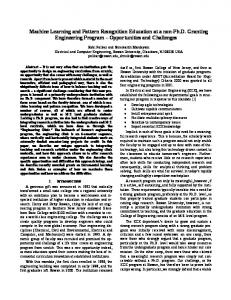
Figure 2. Example of Design Instance ϕ is true on a system s in D, written s � ϕ, when the system s has property ϕ. B. Axiom Rules. A metamodel also defines the inter-element relationships that must be satisfied by all models. These axiom rules define a mapping A from metamodel M to a set of axioms A(M ) in the Σ-sentences. For example, some of these rules state that the set of diagram elements is partitioned into disjoint sets according to the metaclasses they belong to, such as Association, Operation, Class etc. C. Translation Rules. A model states the existence of certain types of elements in the modeled system as well as their properties and interrelationships. The translation rules define a translation mapping T from model m into a set of Σ-sentences such that a system s is an instance of a model m if and only if all Σ-sentences in T (m) are true on system s. For example, a sentence C(id) is generated for each identifier id of concrete type C. D. Hypothesis Rules. These also define a mapping H from models to sets of Σsentences. However, they reveal the context in which models are used, and their application is specific to the modelling context, which here is software design. Suppose the model contains a number of elements of the same concrete type. Then one example of the rules says they are all distinct, another says that the system contains no more than these. Let LM be a modeling language, say UML, defined by a metamodel M . Then DES(LM ) = �S, A, T , H� represents the descriptive semantics and is defined as follows. Definition 1 (Descriptive semantics of models) The descriptive semantics of a model m in LM defined by DES, written [[m]]DES , is the set A(M ) ∪ T (m) ∪ H(m) of Σ-sentences, where Σ = S(M ). A system s in domain D is an instance of model m under the definition of DES, written s �DES m, if s � [[m]]DES . � A tool LAMBDES was reported in [26]. It implements these rules for UML class, sequence and state machine diagrams. For example, Figure 3 shows some of the formulae in SPASS format generated from the UML diagram in Figure 2. These only specify the two classes, however. Fourteen more formulae specify properties of the two operations, six more give the generalisation relationship, and three more link the operations to their classes.
formula(Class(UMLClass_3)). formula(Class(UMLClass_6)). formula(not(equal(UMLClass_3,UMLClass_6))). formula(forall([x],implies(Class(x), or(equal(x,UMLClass_3),equal(x,UMLClass_6))))). formula(isAbstract(UMLClass_3,bTrue)). formula(isAbstract(UMLClass_6,bFalse)). formula(visibility(UMLClass_3,public)). formula(visibility(UMLClass_6,public)). formula(Name(UMLClass_3,M_AbstractClassXX)). formula(Name(UMLClass_6,M_ConcreteClassXX)).
Figure 3. Formulas generated by LAMBDES
2.2
Specification of Design Patterns
In Bayley and Zhu’s approach to the formal specification of design patterns [1, 3], a pattern is a first-order predicate p on UML models. A design model m conforms to the pattern denoted by p, if the evaluation of p on model m is true. For example, here is the specification of the Template Method pattern taken from [3]. Components • AbstractClass ∈ classes • templateM ethod ∈ AbstractClass.opers • others ⊆ AbstractClass.opers Static Conditions • templateM ethod.isLeaf • templateM ethod �∈ others • ∀o ∈ others . ¬o.isLeaf Dynamic Conditions • The template method calls the non-leaf operations. ∀o ∈ others . callsHook(templateM ethod, o) The static conditions relate to the class diagram and the dynamic conditions relate to the sequence diagram. Here, classes denotes the set of classes in the class diagram. If C is a class then C.opers denotes the set of operations of class C. If o is an operation then o.isLeaf is true when o is not redefined in a subclass. So the static conditions state that there must be a class AbstractClass with a non-redefined operation templateM ethod that calls a set others of separate redefined operations. The predicate callsHook(op, op� ) in the dynamic conditions is defined as ∃C ∈ subs(C � ) · calls(op, C.op� ), where calls(op, op� ) denotes that the sequence diagram has messages m and m� in messages, the set of messages, such that m, labeled with operation op, calls m� , labeled with operation op� . The mix of maths and text forming the specification above is meant to be read as a single (commented) predicate in which the variables AbstractClass, templateM ethod and others are existentially quantified and the four conditions are conjoined together into a single predicate on those three variables. The general form for the predicate is ∃v1 : T1 ∃v2 : T2 · · · ∃vn : Tn · (P rs ∧ P rd )
where P rs and P rd are the static and dynamic conditions as predicates and the vi : Ti are the variables free in P rs and P rd . The evaluation of a predicate p on a model m in the context of an assignment α 1 , written Evaα (m, p), is the truth value of p when the free occurences of each variable x in p are replaced by α(x). If Evaα (m, p) = true, we say that model m satisfies predicate p under the assignment α, and write m �α p. When there is no free variable in the predicate p, its truth value is independent of the assignment so the subscript α can be omitted. Finally, we must translate this syntax into that of the LAMBDES tool. The translation is fairly straightforward as both languages use the same basic concepts of objectorientation. For Template Method, we get the following: formula(exists([xAbsClass, xTemplateMethod], and( Class(xAbsClass), ownedOperation(xAbsClass, xTemplateMethod), isLeaf(xTemplateMethod,bTrue), forall([xOps], imply( and(ownedOperation(xAbsClass,xOps), not(equal(xTemplateMethod,xOps))), isLeaf(xOps,bFalse)) forall([xOps], imply( and(ownedOperation(xAbsClass,xOps), not(equal(xTemplateMethod,xOps))), callsHook(xTemplateMethod,xOps)) ))).
2.3
Bridging the Semantic Gap
Although FOL is used both in the descriptive semantics of UML diagrams in [26] and in the formal specification of patterns in [1, 2, 3], the universes of discourses are different. To bridge the semantic gap, the translation mentioned above, which turns predicates on UML models into predicates on software systems, must meet the following correctness requirement. Definition 2 (Correctness of translation) Let p be a predicate on models, p� be a predicate on systems. The predicate p� is a correct translation of p, if for all models m, we have m � p ⇔ ∀s ∈ D · (s � ([[m]] ⇒ p� )). � Once a specification Spec(P ) of pattern P is correctly translated into Spec� (P ) then, given a design model m represented in UML diagrams, we can decide whether the design m conforms to pattern P by proving or disproving the logic statement [[m]] ⇒ Spec� (P ) in FOL. For example, the translated specification of Template Method pattern can be deduced from the LAMBDES formulae that describe the class diagram in Figure 2. The following theorems state that if we can prove [[m]] ⇒ Spec� (P ) in FOL for model m and pattern P , then every system that is an instance of m must conform to P . (Actually, Theorem 2 states this and 1 is preparatory.) Together, 1 An assignment α is a mapping from free variables in p to elements in model m.
these provide the solid foundation required for us to use a theorem prover to check pattern conformance. Theorem 1 Suppose that Spec� (P ) is a correct translation of the formal specification Spec(P ) of pattern P . For all design models m and systems s ∈ D, if s is an instance of model m and m conforms to a pattern P as specified in Spec(P ), we have that (s � Spec� (P )). Proof. By Definition 1, if s is an instance of model m then s � m, which is equivalent to s � [[m]]. By Definition 2 and the condition that Spec� (P ) is a correct translation of Spec(P ), then m � Spec(P ) implies that for all s ∈ D, s � [[m]] ⇒ Spec� (P ). By the consistency theorem of FOL, and s [[m]] we have that s � Spec� (P ). � If Spec(P ) is a correct translation of the formal specification of Spec� (P ), as in Theorem 1, then by Definition 1, for all models m, we have m � Spec(P ) if and only if [[m]] ⇒ Spec� (P ) holds. Thus, the above theorem can be equivalently stated as follows. Theorem 2 Suppose that Spec� (P ) is a correct translation of Spec(P ). For all models m, if [[m]] ⇒ Spec� (P ) is true in FOL, then, for all systems s ∈ D, we have s � m implies s � Spec� (P ). �
A major function of LAMBDES is to translate a UML model and a metamodel into a FOL system. Figure 4 shows the structure and workflow of LAMBDES. Many of the components represent the sets of rules that form the descriptive semantics. Signature mapping and axiom mapping are implemented in the Signature Generator and the Axiom Generator, respectively, and both take the metamodel as the input. To reason about the properties of a metamodel, the Domain Generator generates a set of auxiliary constants and formulas to populate the domain of discourse. Translation and hypothesis mappings are implemented in the Formula Generator and the Hypothesis Generator, respectively. They take a UML model in XMI format and a modeling context as input, respectively. Using a GUI, users can decide which hypothesis rules are to be applied.
3 LAMBDES and LAMBDES-DP
LAMBDES-DP, on the other hand, is LAMBDES extended with a repository of all 23 patterns in GoF, translated from their formal specifications in [3]. If the model has no sequence diagram then only the components and static conditions are used for the conjecture. Otherwise, the dynamic conditions are included too. The Conjecture Generator and the GUI are different from the original LAMBDES tool. This allows the pattern specifications in the repository to be merged with the descriptive semantics of models to form input to the SPASS theorem prover as the conjectures to be proved. The changes are shown in the shadowed box in Figure 4.
In [26], a prototype software tool called LAMBDES (Logic Analyser of Models/Metamodels Based on DEscriptive Semantics) was reported. It translates UML models into FOL systems and facilitates reasoning about models through logical inference. The tool LAMBDES-DP presented in this paper is an extension of LAMBDES with facilities to support reasoning about the conformance of models to design patterns. LAMBDES is integrated with two other software tools: StarUML 2 , a UML modelling tool that allows the user to edit a diagram and export it in the XMI format that LAMBDES uses as input, and SPASS 3 , an automated theorem prover for FOL with equality, which reads in LAMBDES output. SPASS input is a logic system in a text file of four parts: 1. Description: background information; 2. Signature: declarations of the functions, predicates and constant symbols of the logic system; 3. Premises: a list of formulas as the premises of the logic inference; 4. Conjectures: a list of formulas to be proved. For any input, the execution of SPASS may terminate with a proof, terminate with a failure to prove or else run forever without producing any results, because inference in FOL is NP-hard. 2 URL:
http://staruml.sourceforge.net/en/ 3 URL: http://spass.mpi-inf.mpg.de/
The LAMBDES system also allows the users to specify which conjectures are to be proved so that a wide range of logical analyses on models and metamodels can be supported. The Conjecture Generator takes input from a text file and generates the conjectures to be proved. It then combines these with the descriptive semantics of the model as the signature and premise parts to form the input to SPASS.
Metamodel
Model
Modelling tool StarUML User Interface
LAMBDES Metamodel in XMI
Model in XMI
Modelling Context
Proof Goal
Design Pattern Specification
Design Pattern Spec Repository
Domain Generator
Signature Generator
Axiom Generator
Formula Generator
Hypothesis Generator
Conjecture Generator
Auxiliary constants & formulas
Signature
Axioms
Statements
Hypothesis
Conjecture
Logic system for model
Logic system for metamodel
Theorem prover SPASS Inference result
Figure 4. Structure of LAMBDES-DP
4 Experiments We have conducted some preliminary experiments to see how well LAMBDES-DP recognizes design patterns in UML models. There are two types of errors in pattern recognition. A false positive error occurs when a design is incorrectly recognized as an instance of a pattern because the specification of the pattern is not restrictive enough to rule out incorrect uses. In contrast, a false negative error occurs when a design is incorrectly rejected as an instance of a pattern because the specification is too restrictive to take into account some valid uses. Moreover, inference in FOL is NP-hard. If the theorem prover cannot prove a statement within the time and memory space available, we regard the design as not conforming to the pattern; i.e. our use of the tool in this experiment is conservative. This may cause false negative errors. These two types of errors are measured by precision (the rate of false positives) and recall (the rate of false negatives), respectively. Two sets of design instances were produced manually from the diagrams in the GoF book [10]. Set 1 (Class Only): contains a class diagram for each of the 23 patterns in the book. Set 2 (Class + Seq): contains class and sequence diagrams for the only 6 patterns in the book that contain both. Table 1 gives an overview of these design instances. Each row records the number of elements in the model and in its generated descriptive semantics. The columns for the model show the number of classes (CL), operations (OP), inheritance relations (IH), aggregations (AG), life-lines (LL), messages (MG), and the total number of elements (SUM). The columns for the semantics show the numbers of constants (CN), function/predicate symbols (SB) and formulas (FM). There are two reasons why we didn’t use design models from real software systems. First, they are difficult to acquire, as for most open-source projects, only the source code is widely available. Secondly, the informal descriptions of patterns are so ambiguous that it is often debatable [6] whether a pattern should be found in a system or not. Using the examples from the original GoF book [10] avoids such controversies. The experiments consisted of four steps: 1. Use StarUML to produce design instances as UML diagrams and export them as XMI representations. 2. Use LAMBDES to convert these XMI representations to FOL; 3. Use LAMBDES to check these FOL representations for consistency errors, revising them until there are no more errors; 4. For each pattern, use LAMBDES-DP to determine if the model conforms to (i.e. implies the specifica-
Table 1. Overview of Design Instances PATTERN
CL
OP
IH
AG
LL
MG
SUM
CN
SB
FM
ClassOnly Abs Fctry Adapter Bridge Builder Chain Resp Command Composite Decorator Facade Fact Mth Flyweight Interpreter Iterator Mediator Memento Observer Prototype Proxy Singleton State Strategy Temp Mth Visitor Average
5 4 4 4 3 5 4 4 3 4 5 5 4 5 3 4 3 3 1 3 3 2 5 3.7
1 2 2 5 1 3 6 1 0 2 2 1 5 3 4 5 2 1 1 2 2 2 5 2.5
2 1 2 1 1 1 2 3 0 2 2 2 2 3 0 2 1 2 0 1 1 1 2 1.5
3 2 1 2 2 4 2 1 1 1 4 3 2 3 2 3 1 1 1 1 1 0 1 1.8
0 0 0 0 0 0 0 0 0 0 0 0 0 0 0 0 0 0 0 0 0 0 0 0.0
0 0 0 0 0 0 0 0 0 0 0 0 0 0 0 0 0 0 0 0 0 0 0 0.0
11 9 9 12 7 13 14 9 4 9 13 11 13 14 9 14 7 7 3 7 7 5 13 9.6
15 13 11 15 11 19 21 11 6 9 22 18 15 20 12 32 9 9 6 9 9 5 19 13.7
21 20 18 26 16 28 34 17 9 15 31 25 24 29 21 47 15 14 10 15 15 9 33 21.4
132 132 118 188 106 190 250 109 70 100 215 164 165 196 147 324 101 91 76 101 101 72 252 147.8
Class+Seq Builder Command Mediator Memento Observer Visitor Average
4 5 5 3 4 5 4.3
5 3 3 4 6 5 4.3
1 1 3 0 2 2 1.5
2 4 3 2 3 1 2.5
3 4 3 3 2 3 3.0
3 3 3 4 4 3 3.3
18 20 20 16 21 19 19.0
26 30 31 24 32 29 28.7
38 41 41 34 47 44 40.8
240 250 246 205 324 302 261.2
tion of) the pattern. There are three possible outcomes: Proof Found, meaning definitely yes, Completion Found, meaning definitely no, and Time Out, meaning that no proof was found in the maximum time limit that SPASS allows, which is 990 seconds. In our experiments with ClassOnly, every design instance was correctly recognized as conforming to the intended design pattern, giving a 0% false negative error rate. We also checked every design in ClassOnly against the other 22 patterns, but wrongly proved conformance in some cases, giving a 22% false positive rate. This was partly because a pattern can overlap with or specialise another, so the “real” rate should be lower. Nevertheless, [3] argued that this rate could be reduced by taking dynamic features into account. We were able to confirm this by trying the set Class+Seq. We tested each of the six design instances against the other five unintended patterns, and we got twenty-four time-outs and six rejections. If time-out is conservatively interpreted as rejection, the false positive error rate is 0%. These statistics are fundamentally different from their equivalents at code level, because each model can be implemented in many different ways, so comparison with code-level pattern recovery tools may be meaningless, and as far as we know, there is no data available for a direct comparison with model-level tools.
5 Further Work We plan to improve the efficiency of the LAMBDESDP tool, perhaps by using a different inference engine, so that it can handle larger designs, and to experiment with
design models from industry. We note that some code level tools use an intermediate representation of the source code in FOL, e.g. [4, 12, 18], so we will consider integrating our approach with that. Finally, we will enrich the design pattern repository with variants of some patterns and add tool support for pattern composition.
Acknowledgment The work reported in this paper is partly supported by The Reinvention Center through the funding of Undergraduate Student Scholarship Project to R. Amphlett and the China Scholarship Council’s funding of L. Shan’s visit to Oxford Brookes University. The authors are grateful to Prof. Zhi Jin of Peking University and the members of the Applied Formal Methods research group at Oxford Brookes University for valuable discussions.
References [1] I. Bayley and H. Zhu. Formalising design patterns in predicate logic. In Proc. of SEFM’07, pp 25–36. [2] I. Bayley and H. Zhu. On the composition of design patterns. Proc. of QSIC’08, pp27–36. [3] I. Bayley and H. Zhu. Specifying behavioural features of design patterns in first order logic. Proc. of COMPSAC’08, pp203–210. [4] D. Beyer, A. Noack, and C. Lewerentz. Efficient relational calculation for software analysis. IEEE TSE, 31(2):137–149, 2005. [5] A. Blewitt, A. Bundy, and I. Stark. Automatic verification of design patterns in Java. In Proc. of ASE’05, pp224–232. [6] J. Dong, Y. Zhao, and T. Peng. Architecture and design pattern discovery techniques - a review. In H. R. Arabnia and H. Reza (eds.), Software Engineering Research and Practice, pp621–627. CSREA Press, 2007. [7] A. H. Eden. Formal specification of object-oriented design. In International Conference on Multidisciplinary Design in Engineering, Nov. 2001. [8] A. H. Eden. A theory of object-oriented design. Information Systems Frontiers, 4(4):379–391, 2002. [9] R. B. France, D.-K. Kim, S. Ghosh, and E. Song. A UML-based pattern specification technique. IEEE TSE, 30(3):193–206, 2004. [10] E. Gamma, R. Helm, R. Johnson, and J. Vlissides. Design Patterns - Elements of Reusable Object-Oriented Software. Addison-Wesley, 1995. [11] A. L. Guennec, G. Suny´e, and J.-M. J´ez´equel. Precise modeling of design patterns. In Proc. of UML 2000, LNCS 1939, pp482–496. Springer. [12] H. Huang, S. Zhang, J. Cao, and Y. Duan. A practical pattern recovery approach based on both structural and behavioral analysis. J. Syst. Softw., 75(1-2):69–87, 2005.
[13] D.-K. Kim, R. B. France, S. Ghosh, and E. Song. A role-based metamodeling approach to specifying design patterns. In Proc. of COMPSAC’03, pp452–457. [14] D.-K. Kim and L. Lu. Inference of design pattern instances in UML models via logic programming. In Proc. of ICECCS’06, pp47–56. [15] D.-K. Kim and W. Shen. An approach to evaluating structural pattern conformance of UML models. In Proc. of SAC’07, pp1404–1408. [16] D.-K. Kim and W. Shen. Evaluating pattern conformance of UML models: a divide-and-conquer approach and case studies. Software Quality Journal, 16(3):329– 359, 2008. [17] S. R. Kodituwakku and P. Bertok. Pattern categories: a mathematical approach for organizing design patterns. In Proc. of CRPIT’02, pp63 – 73. Australia Computer Society. [18] C. Kr¨amer and L. Prechelt. Design recovery by automated search for structural design patterns in objectoriented software. In Proc. of WCRE’96, pp208–215. [19] K. Lano, J. C. Bicarregui, and S. Goldsack. Formalising design patterns. In Proc. of BCS-FACS Northern Formal Methods Workshop, Sept. 1996. [20] A. Lauder and S. Kent. Precise visual specification of design patterns. In Proc. of ECOOP’98, LNCS 1445, pp114–134. Springer. [21] J. Mak, C. Choy, and D. Lun. Precise modeling of design patterns in UML. In Proc. of ICSE’04, pp252– 261. [22] D. Mapelsden, J. Hosking, and J. Grundy. Design pattern modelling and instantiation using DPML. In Proc. of CRPIT ’02, pp3–11. Australian Computer Society. [23] T. Mikkonen. Formalizing design patterns. In Proc. of ICSE’98, pp115–124. [24] J. Niere, W. Sch¨afer, J. P. Wadsack, L. Wendehals, and J. Welsh. Towards pattern-based design recovery. In Proc. of ICSE’02, pp338–348. [25] N. Shi and R. Olsson. Reverse engineering of design patterns from Java source code. In Proc. of ASE’06, pp123–134. [26] L. Shan and H. Zhu. A formal descriptive semantics of UML. Proc. of ICFEM, pp375–396. [27] T. Taibi. Formalising design patterns composition. Software,IEE Proceedings,153(3):126–153,June 2006. [28] T. Taibi, D. Check, and L. Ngo. Formal specification of design patterns-a balanced approach. Journal of Object Technology, 2(4), July-August 2003. [29] M. Vokac. Defect frequency and design patterns: An empirical study of industrial code. IEEE TSE, 30(12):904–917, 2004. [30] U. Zdun and P. Avgeriou. Modelling architectural patterns using architectural primitives. In Proc. of OOPLSA’05, pp133–146.