Not applicable for low speeds. Simple Position Control. Poor Positioning. Simple Drive Circuit. Disadvantage. Advantage. High maintenance. Reliable. Low Cost.
Motor Selection Criteria REV II DR. TAREK A. TUTUNJI PHILADELPHIA UNIVERSITY, JORDAN 2014
Actuators Actuators are the muscle behind a mechatronics system
that accepts a control command (i.e. electrical signal) and produces a change in the physical system by generating force, motion, heat, flow, etc.
Actuators Selection Affects the system’s dynamic behavior Dominates the power needs Affects the coupling mechanisms of the system
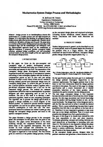
DC vs. AC Motors DC Motors
AC Motors
Advantages
Disadvantages
Simple Speed Control
Not applicable for low speeds
Simple Position Control
Poor Positioning
Simple Drive Circuit
Disadvantage
Advantage
High maintenance
Reliable Low Cost High Power
Motor Requirements The motor must be capable of matching the power
requirements of the driven load.
Therefore, the motor power available should be enough to cope with the anticipated demands of the load.
The motor must have enough torque available on start-
up to overcome the static friction, accelerate the load up to the working speed, and be able to handle the maximum overload.
Some systems also therefore require a “soft start”
whereby the motor torque is gradually increased to allow the load to accelerate gently.
Motor Requirements The operating speed of the motor will be fixed by the
point at which the torque supplied by the motor is just balanced by the torque requirements of the load.
At any other condition, the motor and load will be either accelerating or decelerating. Correct matching of a motor to a driven machine can only be confidently accomplished if both the motor and the load torque–speed characteristics are known.
The motor torque–speed characteristics are usually
provided by the supplier.
Motor Requirements Fans and blowers have a torque–speed characteristic that
increases parabolically from zero as the speed increases.
Such machines do not, therefore, need much motor torque to enable them to start.
High inertia devices like machine tool drives, rolling
mills, and electric lifts require a large torque on start-up to overcome the inertia. Once motion is established the torque requirements tend to decrease with increasing speed. The series-wound dc motors are ideal for these types of loads.
General Objective Get the best performance for the best price Find the smallest motor that fulfills the requirements
Matching objectives Match the motor’s torque with the load torque as close as possible Match the motor’s inertia with the load inertia as close as possible Find a motor that matches or exceeds the required speed
Motor Selection Steps 1.
Determine the drive mechanism
2. Set specifications 3. Calculate the load torque and inertia 4. Select the motor
1. Determine the Drive Mechanism Linear or rotational motion Choose type for linear motion Ball screw, belt pulley, conveyer belt
Choose power transmission Gears Determine the dimensions and mass for the load and all parts Check shaft dimensions – select couplings Check mechanical components for speed and acceleration
limitations
Mechanical Components For linear movements: Conveyor Leadscrew Rack-Pinion Linear Actuator For speed transmissions: Gear Belt Drive Chain Drive For other purposes: Coupling Brake Encoder
Drive Mechanisms
2. Define Specifications Velocity
Frequency response
Acceleration
Operating environment
Motion profile
Temperature
Total mass Friction coefficients
Positioning distance
Resolution
Accuracy
Power
considerations Linear or rotary motion Vertical or horizontal Load variation Jerk limitation Thrust load
3. Calculate inertia and torque Calculate inertia of all moving components Determine inertia reflected to motor
Determine velocity, acceleration at motor shaft Calculate acceleration torque at motor shaft Calculate constant torque at motor shaft Calculate total acceleration and RMS torque at motor
shaft
Velocity Profile
Inertia and Torque
4. Select Motor Select the motor type: DC or AC In general, use AC for constant speed and high torque and DC for speed and position control For DC: Servo, Stepper, or brushless Select the specific motor to use Use Performance (torque-speed) curves supplied by the manufacturers The basic selection criteria are: The motor’s rated speed must be equal to or exceed the application’s maximum speed The motor’s intermittent torque must be equal or exceed the load’s maximum (intermittent) torque The motor’s rated torque must be equal to or exceed the load’s RMS torque The ratio of load inertia to rotor inertia should be equal to or less than 6:1
DC Motor Selection Example
Objective
Motion Profile
Load Calculations
Load Speed
Torque Calculations
Torque Calculations
Motor Requirements
Torque-Speed Curves
Increasing Drive Voltage
Torque-Speed Curves
Ok
Failure
Holding Brake The effect of a holding brake is important for vertical
linear applications.
The main purpose of a holding brake is to relief the motor from maintaining the holding torque during standstill periods in a vertical linear motion application.
The holding brake adds inertia to the motor load,
therefore increases torque and power requirements during acceleration and deceleration
Vertical Applications
Load Inertia and Torque Calculations: Basic Equations
Basic Calculations The motor selection is based on speed, inertia and
torque comparisons. The calculation of mechanical devices is used to determine these parameters. Even the most complex mechanical devices are
calculated based on three “basic” components:
Solid Cylinder Hollow Cylinder Solid Rectangular
Solid Cylinder
Hollow Cylinder
Rectangular Block
Basic Equations
Basic Equations
Basic Equations
Basic Equations
Disc
Chain Drive
Gears
Conveyer Belt
Lead Screw
Rack and Pinion
Load Calculations
Motor Load Transmission
Example: Servo Motor Selection
Example: AC Motor Selection
Summary Motors are selected in order to provide the
appropriate motion to the plant under control
Motor selection is an important part of the
mechatronics design process
This selection affects important issues, such as
dynamic behavior and power consumption
The selection process can divided into five steps:
References Wilfred Ross, Copperhill technologies applications,
2007 Oriental Motor General Catalogue 2012/2013