Memory Architecture for Efficient Utilization of SDRAM: A Case Study of the Computation/Memory Access Trade-Off Thomas Gleerup
[email protected]
Hans Holten-Lund
[email protected]
Jan Madsen
[email protected]
Steen Pedersen
[email protected]
Technical University of Denmark Department of Information Technology DK-2800 Lyngby, Denmark
ABSTRACT This paper discusses the trade-off between calculations and memory accesses in a 3D graphics tile renderer for visualization of data from medical scanners. The performance requirement of this application is a frame rate of 25 frames per second when rendering 3D models with 2 million triangles, i.e. 50 million triangles per second, sustained (not peak). At present, a software implementation is capable of 3-4 frames per second for a 1 million triangle model. By using direct evaluation of certain interpolation parameters instead of forward differencing, writing back parameters to SDRAM is avoided. In software, forward differencing is usually better, but in this hardware implementation, the trade-off has made it possible to develop a very regular memory architecture with a buffering system, which can reach 95% bandwidth utilization using offthe-shelf SDRAM. This is achieved by changing the algorithm to use a memory access strategy with write-only and read-only phases, and a buffering system, which uses round-robin bank write-access combined with burst read-access.
Keywords Memory architecture, 3D graphics, case study.
1. INTRODUCTION Medical scanners such as CT (Computed Tomography), MR (Magnetic Resonance), and PET (Positron Emission Tomography) are in use in many hospitals for diagnostic and surgery planning purposes. The interpretation of the two-dimensional output of these scanners is difficult even for highly skilled physicians. To improve the quality and time consumption of the analysis of the two-dimensional “slices”, it is desirable to be able to render a three-dimensional image of the data in real time. A surface model consisting of triangles can be generated from the two-dimensional images that are output from the medical scanner. Such a model typically contains about two million triangles that have to be rendered in real time. This leads to a very high, sustained triangle rate of 50Mt/s (million triangles per second) at 25f/s (frames per second). A tile-based rendering algorithm has been implemented in soft-
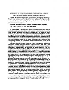
Figure 1: Buddha model [9] containing 1 million triangles and hip joint [3] containing 32,000 triangles, both rendered with the Hybris software [5]. The grid super-imposed on the Buddha indicates the tile size of the renderer (32 by 32 pixels). ware [5]. This highly optimized software achieves a frame rate of about 3-4 f/s on a dual Pentium III 500MHz Windows NT PC when rendering the Buddha [9] model containing 1 million triangles, see fig 1. The Buddha model is commonly used for 3D graphics benchmarks. For comparison, a model of a hip joint is shown in fig. 1. This model has been generated from sub-sampled CT data to get a model with a low triangle count (32,000) to allow real-time rendering in software. Models like this are used in [3] for surgery planning. Although the performance of the software is higher than what is achievable using game-oriented 3D hardware accelerators, it is evident that considerable speed-up is needed to reach 50Mt/s. High-priced systems from e.g. Silicon Graphics are able to deliver the required performance, but the goal of this work has been to develop a PC-based cost-effective solution. The low cost will enable each physician to have his own 3D workstation, which can also be used for administrative purposes in a familiar environment. The rest of the paper is organized as follows. Section 2 describes the 3D graphics system and discusses the trade-off between calculations and memory access. Section 3 motivates the use of SDRAM and briefly states the basic properties. Furthermore, the employed memory architecture is presented together with simulation results. Section 4 presents the synthesis and simulation results of the current implementation of parts of the 3D graphics system. Finally, section 5 gives some concluding remarks.
2. 3D GRAPHICS SYSTEM
Rendering a triangle requires the following steps. First, the geometry is transformed to screen coordinates, and a lighting equation is evaluated at each vertex. Then, the triangle interpolation parameters are calculated, and the triangle is inserted into the triangle heap (data structure for storing triangles). After all triangles have been processed this way, the tile renderers can begin to process the triangles in the triangle heap. The rendering pipeline is shown in fig. 2. Rendering a triangle is done by determining which screen pixels are touched by the projected triangle, and which color to set them to. To do this we interpolate parameters for each triangle (edges, colors, depth). A triangle has three edges, which are connected by their vertices. Interpolation starts from the topmost triangle vertex. The parameters are first interpolated along the edges of the triangle, to determine starting interpolation values for interpolation along each scanline. Fig. 3 illustrates interpolations for rendering a triangle. While interpolating the parameters along scanlines, each parameter is checked against the current value in the tile buffer, and the final pixel value is written back to the tile buffer. Because of the high bandwidth requirement of this read-modifywrite cycle, we use high-bandwidth on-chip memory for the tile buffer. This also allows for arrangement in parallel of the triangle rendering, as several tile buffers can be in use at once. Since the order of the triangles is not known, the triangles must be sorted according to which tile they belong prior to processing each tile. The sorting, which facilitates the use of a small local memory for the tile processing, is done by inserting the triangles into the triangle heap. If a global frame buffer had been used (one large tile), the triangle heap would not be necessary. However, this would make parallel tile processing impossible, and requires very
3D Graphics System
Host
3D Surface Model Data
ISO Surface Model Generation
Scanner Data
Medical Scanner
PCI (Fig. 4 & 5)
3D Surface Model Data
3D Transformation, Lighting, Projection, Clipping
Rendering
Front-end
Back-end
To display
Figure 2: 3D graphics system. The back-end is shown in more detail in fig. 4.
Z
Scanline number
The job of the tile rendering algorithm [1] is processing and rendering millions of triangles to create the final image on the screen, as seen in fig. 1. As the triangles may be arbitrarily transformed, we do not know where on the screen a triangle may be placed. Since the screen has been divided into tiles (see Buddha in fig. 1), we have to determine to which tiles a triangle belongs. When all triangles belonging to a tile have been identified, we can start rendering the tile by filling in the pixels covered by each triangle with specific color values. The pixels are held in the tile buffer while processing the tile, and later written to the display buffer. Another renderer based on this idea is presented in [6], however, they do not solve the bandwidth problems of the triangle heap, which will be discussed later.
Y
X 1 2 3 4 5 6 7 8 9 10 11 12 13 14 15 16 17 18 19 20 21
s1
ds dz
ds dy
s2
ds dx
s3
Currently rendered span
Figure 3: Interpolations when drawing a triangle on the screen. high-bandwidth memory for the frame buffer, yet this is how most current PC 3D graphics hardware works, e.g. Nvidia Gforce 256 with 256 bits wide DDR SDRAM. A global frame buffer is best suited for rendering large triangles. In this paper, we focus on the implementation of the back-end of the tile-based renderer. The parts not covered by this paper are the geometry transformation, culling, clipping and triangle setup, which occur prior to insertion into the triangle heap. A connection to a host computer via a PCI bus is used to transmit triangle geometry data to the 3D renderer’s memory. Prior to transmission to the renderer, the host computer generates triangle geometry data from the volumetric data of the medical scanner, using an iso-surface extraction algorithm [7].
2.1 Direct Evaluation versus Forward Differencing When interpolating the parameters required for rendering a triangle, we can choose either direct evaluation or forward differencing to evaluate the interpolated parameters. To evaluate an interpolation of a parameter between two values, the difference quotient, ∆p/∆x, has to be calculated. Now, we can interpolate the values between the two endpoints by directly evaluating the equation: p(x) = p0 + x ∗ ∆p/∆x. To cover N interpolated values, direct evaluation requires N additions + N multiplications. Alternatively, we can interpolate the values between the two endpoints by incrementally adding the difference quotient, starting from the first value. Equations: p(0) = p0, p(x) = p(x-1) + ∆p/∆x. This is called forward differencing, and only N–1 additions are required. Thus, we have saved one addition and N multiplications. However, in more complex algorithms, such as rendering of triangles in 3D, the savings are even greater, although additional setup calculations are required. The above example suggests that forward differencing is superior to direct evaluation, and this is usually true when an algorithm is implemented in software. However, when implementing an algorithm in hardware, only looking at the number of arithmetic operations doesn't tell the whole story, because memory issues are not taken into account. Memory issues are still important for software, but the memory architecture of the computer cannot be changed to optimize the software.
When using forward differencing, the current parameters have to be stored and later restored when the next data values are to be computed. In the simple example above, this is not really an issue, but in a highly complex hardware system using SDRAM, this read-modify-write behavior can have a very severe impact on performance.
3D model must reside on the accelerator board to avoid the PCI/AGP bottleneck. The memory requirement of this application is approximately 200MB, which implies the use of SDRAM due to cost constraints. The required bandwidth in some parts of the 3D-graphics pipeline is 1,600MB/s making memory bandwidth the performance bottleneck [4].
In the tiled triangle renderer, one approach is to use forward differencing, and write the current values back to the triangle heap when reaching the tile border. This will allow the tile below to continue the interpolation from the values of the previous tile. While this works fine in software, the memory writes create problems for the hardware implementation. This is fixed by only using forward differencing within each tile, initialized by direct evaluation interpolation of parameters from the triangle heap. Fig. 4 shows how triangles are written into the triangle heap, and read from SDRAM by the triangle renderer. The extra calculations necessary for direct evaluation in hardware outweigh the cost of storing intermediate parameters. Note that in this case the parameters could not be stored on-chip since a large number of triangles may cross a tile boundary. The tiled approach allows the renderer to extensively utilize forward differencing without the memory overhead of parameter write-back, with a low overhead for direct evaluation.
3.2 SDRAM Properties SDRAM has a high potential bandwidth, but in practice, the bandwidth utilization is low due to the random-access nature and read-modify-write dependencies of an application. E.g., a 100MHz 64-bit SDRAM has a burst-access bandwidth of 800MB/s versus a single-word random-access bandwidth of only 100MB/s [8]. In addition, the latency of read- and write operations is asymmetric. The reason that the random-access bandwidth is low for SDRAM (in contrast to SRAM) is that it takes some cycles to open a memory page for reading or writing. Consecutive accesses to the same page can be performed at full clock speed, e.g. 100MHz. Most SDRAMs are divided into four banks, which can each have a memory page open. This can be exploited to achieve very high bandwidth utilization by accessing the banks in a round-robin manner, thus hiding the page open/close operations.
Double Buffer
Triangle Vertices
Triangle Setup, Sorting
3.3 Algorithm Properties/Requirements
SDRAM Triangle Heap
Rendering Tile Buffers
The 3D-graphics rendering algorithm used in this application has a number of properties, which should be satisfied for the HW/SW architecture transformation to be effective:
Pixels To display buffer
Figure 4: Overview of 3D graphics back-end.
1.
The input data is a (long) stream of unsorted data records.
2.
The algorithm operates on groups of data that need to be sorted prior to these operations.
This section will discuss the memory architecture that is used in the back-end of the 3D graphics pipeline (fig. 2 & 4) to utilize almost the full bandwidth of SDRAM. However, we will do this by taking a more abstract view on the architecture to make it more easily understandable.
3.
The algorithm should be rewritten to allow for write-only and read-only phases, i.e. trading in more calculations by using direct evaluation instead of forward differencing.
3.1 Substantial Memory Requirements
4.
SDRAM is used.
Mainstream 3D accelerator boards claim to have high performance but in reality these boards are not capable of providing the required performance for large 3D models due to the PCI/AGP bus. To obtain a high, sustained triangle rate, the memory for the
5.
Memory bandwidth is the performance bottleneck.
6.
Input data should be organized such that SDRAM burst mode can be utilized.
3. OBTAINING HIGH BANDWIDTH UTILIZATION
1M randomly tagged records, 0