IEEE-20180
Microstrip , Slotted Rectangular Waveguide Array and Patch-fed Rod Antenna Design and Simulation for Gigabit Wireless Communications at 60 GHz T. Rama Rao and S.Ramesh RADMIC, Dept. of Telecommunication Engineering, SRM University, Kattankulathur - 603203, TN.
[email protected],
[email protected]
Abstract-This paper deals with the design of 2x2 Microstrip,
proliferate across very wide variety of consumer devices over the
Slotted rectangular waveguide antenna array and Patch-fed rod
next years. Within these Mm wave radio technologies, various kinds
antennas
of wireless data transmissions and advanced information services are
wireless
needed
for
ultra
communication
high-speed,
systems
which
ultra
high-capacity
work at
Millimeter
waves at 60 GHz for different multimedia applications in indoor environments and illustrates its specifications and requirements. The antenna in such systems requires high gain, high-efficient, wider beamwidth and high performance design specifications. The designed antennas were simulated using electromagnetic software Agilent's EMPro and Ansys HFSS. Keywords-Millimeter
Waves,
60
2x2
GHz,
expected to develop with/without license. Strong attenuation over the free space due to the smaller wavelengths, oxygen absorption and severe attenuation by walls allow frequency reuse and user privacy [4, 5, 6] makes Mm waves based wireless technologies an attractive proposition for ultra-high-speed new generation WLANIWPAN's [7]. Therefore, our present work targets on addressing challenges in
Microstrip
and
Slotted rectangular waveguide Antenna Array, Patch-fed rod antenna, Design and Simulation.
designing Microstrip, Slotted rectangular waveguide antenna array Patch-fed rod antenna for the realization of Mm wave based wireless communication networks
[8],
particularly at 60 GHz utilizing
Agilent's EMPro and Ansys HFSS simulations. The paper is I.
In
today's
organized as follows; Section 2 deals with technical challenges,
INTRODUCTION
technological
digital
society,
wireless
communication technologies has become an increasingly important part of daily life and emerged leading to significant
especially on Antennas design and development. Section 3 deals with results obtained in our present work and discussions. Finally, Section 4 gives conclusions.
changes in lifestyles. From cellular mobile phones to satellite whether they transmit or receive is the antenna [1]. The ever increasing need for mobile/wireless communications and the emergence
of
new generation
technologies required
TECHNICAL CHALLENGES
II.
dishes, the common element in all these wireless systems Antennas
are
the
most
critical
& ISSUES
component
ill
wireless
communication systems, and can be regarded as a means for
an
radiating or receiving Mm waves. Antennas with excellent design
efficient design of antennas of smaller size for wide range of
can improve the communication performance. Due to the short
variety of applications with style and performance Variety
of
wireless
applications
such
as
online
[2].
wavelengths of the Mm waves, it is easy to obtain an electrically
video
larger antenna aperture. It means that high gain and angular
streaming, online games, digital video streaming, medical
resolution are easily obtained. However, it is also difficult to develop
data collection and health care applications etc, desires some
an
special requirements, such as high data rate, larger capacity,
requirement and large metal and dielectric loss.
Mm-wave
antenna
because
of
the
rigorous
manufacturing
limited communication area, and high angular resolution [3]. Despite many advantages offered and high potentials applications Recently, emerging systems of Gigabit (GiFi) wireless
envisaged in 60GHz, there are number of technical challenges and
higher
open issues that must be solved prior to the successful deployment of
frequencies at 60 GHz with capabilities of GiFi data rates.
this technology. These challenges can be broadly classified into
Corresponding to these ultra-high data rates, the bandwidth of
channel propagation, antenna technology, RF section, and choice of
communications
are
pushed
into
regimes
of
operation are also stretched to millimeter (Mm) waves at 60
modulation. Many types of antenna structures are considered not
GHz. The radio systems at Mm wave frequencies including
suitable
its antennas are required to enable these wide bandwidth
requirements for low cost, small size, light weight, and high gain. In
for
60GHz
WPAN/WLAN
applications
due
to
the
transmissions for high-speed broadband wireless local area
addition,
networks (WLAN) and wireless personal area networks
approximately constant gain and high efficiency over the broad
(WPAN) communication systems which are expected to
frequency range (57-66 GHz) [8, 9].
60 GHz antennas also require to be operated with
ICCCNT'12 h d 26t _28 l July 2012, Coimbatore, India
lEEE-20180
From the configuration standpoint, most antenna forms in
L
Mm waves are similar to those in microwaves. However, some forms are more suitable and popular in Mm-wave
=
{I I {2f, �JIO�O J�reff }} -
2 LlL
(4)
Using electromagnetic software Agilent's EMPro the simulation
applications, such as microstrip, slot and rod antenna. The
is carried out, with the spacing defining for x= 3.5
choice of antennas for Mm wave depends on the applications
mm between the antennas a maximum gain of 13 dBi is achieved.
rum
and y =3.2
and the propagation environment, but clearly both a broad
Study on
beam antenna and directional antennas are required. The
A maximum gain for al = 0.2
microstrip antenna, slot antennas are belongs to broad beam
optimization [14, 15]. The size of the patch array for the optimized
category and rod antenna is directional.
array gain due to the effect of feed network is perceived.
spacing is 5.35
rum
rum
and bl=0.45
rum
is seen after
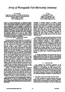
by 4.65 mm is shown in the Fig. l.
Recently, the technology of planar integrated antenna has been developed for Mm wave applications due to the trend of the integration in radio frequency front-end circuits and
rnm __
•
systems. As the operating frequency of wireless systems move into Mm wave range in order to provide gigabytes per second service, there is an increasing demand of high gain
.65
antennas used for consumer devices. The desired antenna has to be compatible with integrated circuits, and possess high gain and small side lobe. The antenna, when integrated into consumer devices, should also have the benefits of small size and low production cost [10, 11]. However, wider beamwidth, high directional antennas either require large size such as Microstrip or Slotted rectangular waveguide array or Patch fed rod antennas.
Fig.
I. Top view of2x2 Microstrip array antenna with dimensions
Slotted rectangular waveguide antenna array is a very low loss III.
transmission line. Energy contained inside a waveguide can be
ANTENNAS DESIGN
The 2x2 Microstrip array antenna is a planar structured with high gain and efficient radiation which can be integrated conveniently with the rest of the system. A typical single rectangular patch antenna can provide 7 dBi gain and greater than 30° beamwidth when its fundamental mode (TMIO) is excited. The procedure assumes that the specified information includes the dielectric constant of the substrate resonant frequency
(£-),
( c,) ,
the
and the height of the substrate (h).The
design proceeded with the help of the theory and below equations [12, 13]. For an efficient radiator, a practical width
radiated and transmitted by arrays of slots which act as antenna elements along the waveguide. Slots are ideal antenna elements that can easily be incorporated into the waveguide walls without the need for special matching networks that other types of antennas often require. Waveguides have a defined waveguide wavelength
(Ag),
which is related to the frequency of operation inside a waveguide, and which is different from free-space wavelength. A waveguide has a cut-off frequency (fc) below its operating frequency. The cut-off wavelength
(Ac)
and waveguide wavelength
(Ag)
are related to each
other as shown in the equations [16],
(W) that leads to good radiation efficiency is calculated using,
W=1I(2f,�tto�o){.J2/(';r+l)}=
Vo/2f,
{.J2/(';r+1)}
(5)
(1)
where Yo is the free-space velocity of light. The effective
(6)
dielectric constant of the Microstrip antenna calculated using,
�
iff ={(�r +1)/2+(�r -1)/2}{1+(l2hlw)}-
(I/Z)
(2)
re
Once W is found then using above equation values to determine the extension of the length
LlL using,
&/h=0.412{(;reff+O.3) W/h+0.264}/{(;reff-0.258) W/h+O.8} The length using
(L)
(3)
of the patch can now be determined by
where subscripts m and n represent the number of
YzAO
variations
along the large 'a' and small 'b' inside dimensions respectively. Slots need to be narrow and approximately
YzAO
long to ensure that
the distribution of the electric and magnetic fields along them is sinusoidal. The slot length can be extended or reduced by
Yz5Ao
without interfering with the frequency of operation. The slots need to be narrow and their width small compared to their length. The ratio of slot width to its sloth length should be 1 :9. The Spacing between the slots should be approximately equal to
YzAg.
If this spacing is
changed it causes a shift in the operating frequency. This distance
ICCCNT'12 h tll 26t _2S July 2012, Coimbatore, India
IEEE-20180
between slot centers needs to be accurate to ensure that the antenna operates properly at operating frequency [20].
design the patch-fed rod antenna. A rod antenna is designed with a patch. The rod consists of a cylindrical and tapered part. The rod is fed by a patch which is sequentially energized by a microstrip line connected to a coaxial connector. The antenna configuration can be
-i" .t
Slot: t:OTo- _-_- _-_-
easily built and integrated with other millimeter-wave functional modules or planar circuits [19, 20]. A patch-fed patch antenna of 1.98 mm by 0.56 mm has been designed at 60GHz. The patch
SIOot:
-30 -
I
--
V
'" ./
...... :\
r
-40
THETA
Fig. 4(a). 2D radiation pattern of the 2x2 Microstrip array antenna
Fig. 3. Patch-fed rod antenna
A dielectric rod in the patch-fed rod antenna can act as a guide for electromagnetic waves. Considerable millimeter wave power propagates through the surface of the rod and is radiated to free space. This radiation tendency is used to
Fig. 4(b). 3D radiation pattern of the2x2 Microstrip array antenna symmetric around the normal axis
ICCCNT'12 h d 26t _28 l July 2012, Coimbatore, India
IEEE-20180
The
Slotted
rectangular
waveguide
antenna
array
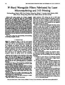
simulation carried out using Agilent's EMPro. With the antenna dimensions a= 3 rum and b =1.5 rum and 0.01 rum wall thickness, a maximum gain of 14.59 dBi is achieved. The operating frequency of the antenna was used to determine all physical dimensions of the waveguide and the radiating slots. The simulated results were used as guidelines for the various slot parameters. The slot length was kept at �A.o (0.24mm) according to the waveguide theory, while the slot width was calculated to be 0.02rum using the 1:9 width-to length ratio that was identified using the simulated results. The spacing between the slots is 0.045rum. The parameters
Fig. 5(b).
VSWR for the slotted rectangular waveguide array antenna
and dimensions are shown in the Table. I for a rectangular waveguide slot array antenna with 8 slots.
TABLE I. PARAMETERS OF WAVEGUIDE SLOT ARRAY DESIGN
Parameters
Values
Slot position from port
162 mm
Waveguide wall thickness
3 mm
Slot to top
40.5 mm
Recta�ular waveguide short side
44 mm
Slot length
58. 3 mm
Slot width
6.5 mm
Number of slots on each side
8
Slot spacing
81 mm
Slot offset
9.2 mm
Rectangular waveguide wide side
94 mm
Fig. 5(c). 3D Radiation pattern for the slotted rectangular waveguide array antenna
The patch-rod antenna has been simulated and analyzed using
The slot array antenna is designed with 8 numbers of slots by using a substrate copper with specifications 5.8x10⁷ S/m
Ansys HFSS V14.0. Rather the results have been observed. The
conductivity and with relative permittivity of 1. Simulations
choice of design parameters mainly the rod height and the position of
had also shown that, as the number of slots increases gain increases by 3dBi. The simulation of an 8-slots design shows a stable 14.59 dBi gain, VSWR 2.43 and beamwidth 22.6° at 60 GHz is achieved. The Gain, VSWR and 3D radiation pattern of the slotted rectangular waveguide antenna array is shown in the Fig. 5(a), 5(b) and 5(c) respectively. , ..
1 .. .. ..
, ....
1' ..... '.
, ..
1 ..... "
...........-. __ .......... -...... -....... � .... �--
rod with respect to patch.
The radiation pattern and 2D gain total
results for patch-fed rod antenna are given in Fig. 6(a) and 6(b) respectively. The Patch-fed rod antenna is more efficient with gain and beam width when compared to probe fed patch antenna [21]. The compromise between high gain and small side lobe is obtained by the proper choice of design parameters mainly the rod height and the position of rod with respect to patch.
........- ........ ___ ...-. ....... --.-.--..
....... _.
compromise between gain and side lobe is obtained by the proper
AnsotLLC
Radiation Pattern 3 OJlVe�fo
........... .. ...- , ...
, ......
.. " ...
, .... ..
-dB(GailTClaI)
.....W!.
1
Serupl:LsstAdaplilte
�....-, .......
.... ...-.-... _____ ............. _ .......__ a.
"WI'
1 .... .
Freq='6OGH!:'RlP'Odeg'
1'-"
d8(GailT«aI) 5«Iipl:lastAdaplilte Freq='6OGH!:'AlP'9CkJeg
90
-180 lIII
Fig. 5(a). Gain for the slotted rectangular waveguide array antenna
Fig. 6(a). Radiation pattern of patch-fed rod antenna
ICCCNT'12 h d 26t _28 l July 2012, Coimbatore, India
IEEE-20180 Ansoft LLC 15.oo
XY Plot 5
..�
_t�����
Pa1ch_Antenna_ACKv1
--t-------.:..:....:. .: � ..:.:: -1:---
T
"' "· �,
-dB(GainTctaO Setupl:LastAdap\i.te
1 0.00
Freq:'600It'AlF():jeg'
5.00
-
-dB(GainTctaO Setupl:LastAdap\i.te Req:'600It'AlF9)jeg'
+-
[3]
S.K.Yong, "Multi giga bit wireless through millimeter wave in 60GHzband", in Proceedings of Wireless Conference Asia, Singapore, November 2005.
[4]
Teshirogi and T. Yoneyama, Eds. "Modern Millimeter-Wave Technologies", Ohmsha Ltd., Tokyo, Japan, 200I.
[5]
Hans Schantz," The Art and Science of Ultra wideband Antennas", Artech House, Norwood, MA, USA, 2005.
0.00
+-+
-
[6]
"Next-Generation Broadband Wireless Access Technologies," NTT Technical Review, Vol. 2, No. I, pp. 12-63, 2004.
[7]
T. Ihara and K. Fujimura, "Research and development of millimeterwave short range application systems," Trans., IEICE, Vol. E79-B, No. 12, pp. 1741-1753,
-15.00
Dec. 1996. [8]
-2 0.00
"60 GHz technology & Sons
for Gbps WLAN and WPAN: From TheolY to Practice", John Wiley Ltd., 201 I.
-25.00 - 0 3 ·
Su-Khiong Yong, Pengfei Xia and Alberto Valdes Garcia,
� 2-:i00�.00-� .15'0.00--.,"T00.� . CC .00�� 0'.00 --5"'0.00- 00"'. 00�00 - �� 50 00.00 ' 5TO. 00- -2 -:1 1� Theta [deg[
[9]
FCC" First Report and Order", February 2001, http://hraun-foss.fcc.gov/edocs public
[10] Shao-Qiu Xiao, Ming-Tuo Zhou Yan Zhang, "Millimeter Wave Technology for
Fig. 6(b). 20 gain Total of patch-fed rod antenna
Wireless LAN, PAN and
MAN", Auerbach Publications, 2008.
[II] C. A Balanis," Antenna Theory Analysis and Design", John Wiley, New York, USA, 1997. V.
CONCLUSIONS
[12] C. Kamfelt, P. Hallbjorner, H. Zirath, and A Alping, "High gain active microstrip
Broadband Mm-wave transmission in the 60 GHz range enables WLAN/WPAN systems with regard to increasing data rates. The use of mm-wave techniques offers many
[14]
The
Agilent's EMPro
designed
and Ansys
antennas HFSS
simulated
software.
IEEE
Millimeter-Wave Wireless
Applications",
in
Xihui Tang, H. Wong, Yunliang Long, Quan Xue, and K. L. Lau, "Circularly Shorted
Patch
Antenna
on
High
Permittivity
Substrate
LTCC with embedded-cavity substrates", IEEE Trans. Antennas
& Propagation,
vol. 56, no. 9,pp. 2865-2874, Sep. 2008. [16]
A Rosen, R. Arnantea, P. Stabile, A Fathy, D. Gilbert, D. Bechtle, W. Janton, F. McGinty, J. Butler, and G. Evans, "Investigation of active antenna arrays at 60 GHz", IEEE Trans. Microw. Theory. Tech., vo1. 43, no. 9, pp.2117-2125, Sep. 1995.
[17] Roland A Gilbert, "Waveguide slot antenna arrays" McGraw Hill, 2007.
width of 40°, Slotted rectangular waveguide array antenna has
[18]
The reasonable agreement with the simulated results verifies the designed antennas can be used for different multimedia applications in indoor environments at Mm-wave frequency 60 GHz.
with
& Propagation, VOL. 60, NO. 3,
Microstrip array antenna has a gain of 13 dBi and a beam
rod antenna has a gain of 10.8 dBi and a beam width of 40.4°.
IEEE
pp.1588-1592,March 2012.
2x2
a gain of 14.59 dBi and a beam width of 22.6° and Patch-fed
Trans.
[15] A Lamminen, J. Saily, and A Vimpari, "60 GHz patch antennas and arrays on
using
The
Emerging
Wideband" in IEEE Transactions on Antennas
communications require high gain, high efficiency and more environments.
for
Polarized
the requirements and specifications of different antennas
beam width specifically for multimedia applications in indoor
WLAN/WPANapplications,"
Transactions on Ant. and Prop. Vol. 59, NO. 5, pp.1742-1747, May 201 L
state-of-the-art design flow is required. This work investigates
at Mm-waves at 60 GHz. The antennas for GiFi wireless
60-GHz
Nezhad-Ahmadi, and Safieddin Safavi-Naeini, "Optimized Microstrip Antenna Arrays
radio techniques at lower frequencies. But for commercial
needed for GiFi wireless communication systems which work
for
[13] Behzad Biglarbegian, Mohammad Fakharzadeh, Dan Busuioc, Mohammad-Reza
advantages for short-range wireless systems compared to applications, a cost effective process technology along with a
antenna
Microw. Theory Tech., vol. 54, no. 6, pp. 2593-2603, Jun. 2006.
A Bakhtafrooz and A Borji, "Novel Two-Layer Millimeter-Wave Slot array antennas
based
on
substrate
integrated
waveguides",
in
Progress
In
Electromagnetics Research, Vol. 109, 475-491, 2010. [19] Y. Shiau, "Dielectric rod antenna for millimeter wave integrated circuits," IEEE Tran. Microwave Theory Tech., vol. 24, no. 11, pp. 869-872, Nov. 1976. [20] S. Kobayashi, R. Mittra, and R. Lampe, "Dielectric tapered rod antenna for millimeter wave applications," IEEE Trans. Antennas
& Propagation, voL30, no.
1, pp. 54-58, Jan. 1982. [21] Kao-Cheng Huang and Zhaocheng Wang , "V-band Patch-fed rod antennas for high data-rate wireless communications", in IEEE Ttransactions on Antennas and Propagation, vol. 54, no. 1, pp.297-300, January 2006.
ACKNOWLEDGMENT
Authors are very much grateful to DRDO, Govt. of India for their financial backing to carry out this research work.
REFERENCES [1]
P. Geddes, "The Life and Work of Sir Jagadish Longmans, Green
[2]
& Co., 1920.
C. Bose", New York,
AD. Oliver, "Millimeter wave systems-past, present and future", lEE Proceedings, vo1.l36, no. I, pp. 35-52, 1989.
ICCCNT'12 h tl1 26t _28 July 2012, Coimbatore, India