This article was downloaded by: [Jacob Grobman] On: 06 April 2015, At: 14:58 Publisher: Taylor & Francis Informa Ltd Registered in England and Wales Registered Number: 1072954 Registered office: Mortimer House, 37-41 Mortimer Street, London W1T 3JH, UK
Architectural Science Review Publication details, including instructions for authors and subscription information: http://www.tandfonline.com/loi/tasr20
Microclimate on building envelopes: testing geometry manipulations as an approach for increasing building envelopes' thermal performance a
b
Yasha J. Grobman & Yosie Elimelech a
Faculty of Architecture and Town Planning, Technion, Israel Institute of Technology, Haifa, Israel b
Refael, Advanced Defence Systems, Israel Published online: 02 Apr 2015.
Click for updates To cite this article: Yasha J. Grobman & Yosie Elimelech (2015): Microclimate on building envelopes: testing geometry manipulations as an approach for increasing building envelopes' thermal performance, Architectural Science Review, DOI: 10.1080/00038628.2015.1025688 To link to this article: http://dx.doi.org/10.1080/00038628.2015.1025688
PLEASE SCROLL DOWN FOR ARTICLE Taylor & Francis makes every effort to ensure the accuracy of all the information (the “Content”) contained in the publications on our platform. However, Taylor & Francis, our agents, and our licensors make no representations or warranties whatsoever as to the accuracy, completeness, or suitability for any purpose of the Content. Any opinions and views expressed in this publication are the opinions and views of the authors, and are not the views of or endorsed by Taylor & Francis. The accuracy of the Content should not be relied upon and should be independently verified with primary sources of information. Taylor and Francis shall not be liable for any losses, actions, claims, proceedings, demands, costs, expenses, damages, and other liabilities whatsoever or howsoever caused arising directly or indirectly in connection with, in relation to or arising out of the use of the Content. This article may be used for research, teaching, and private study purposes. Any substantial or systematic reproduction, redistribution, reselling, loan, sub-licensing, systematic supply, or distribution in any form to anyone is expressly forbidden. Terms & Conditions of access and use can be found at http:// www.tandfonline.com/page/terms-and-conditions
Architectural Science Review, 2015 http://dx.doi.org/10.1080/00038628.2015.1025688
Microclimate on building envelopes: testing geometry manipulations as an approach for increasing building envelopes’ thermal performance Yasha J. Grobmana∗ a Faculty
and Yosie Elimelechb
of Architecture and Town Planning, Technion, Israel Institute of Technology, Haifa, Israel; b Refael, Advanced Defence Systems, Israel (Received 19 October 2014; accepted 1 March 2015 )
Downloaded by [Jacob Grobman] at 14:58 06 April 2015
The paper presents a theoretical framework for employing complex geometry on the building’s envelope for increasing thermal performance. It argues that by manipulating the geometry of the façade’s exterior surface, it is possible to achieve a microclimate that will act as a thermal barrier. The argument is tested via computational fluid dynamic simulations that examined the relationship between various airflows and geometry in different sections of the building envelope. It presents the air velocity and thickness of the outer boundary layer that is created on the suggested geometries. The paper concludes with an analysis of the results and a discussion on the potential of each section to create the best-performing microclimate. Keywords: microclimate; building envelope; thermal insulation; computational fluid dynamics; complex geometry
Introduction During the entire history of construction, the basic structure of the building envelope, a laminated entity made of different layers that are used as a barrier, has remained largely unchanged. Ever since the modernist separation between the structure and the building envelope, the development of building envelopes has concentrated mainly on finding new materials, combining materials, or optimizing the performance of the building envelope’s various layers and their combined performance. As opposed to the complex cellular structure of natural skins, traditional building envelopes are typically based on flat orthogonal geometry, repetition, limited functions, and structural homogeneity. Recent developments in digital fabrication seem to suggest that in the near future, the possibility of fabricating complex architectural forms will be almost limitless. Therefore, it seems both necessary and desirable to examine new approaches to design and fabrication of building façades. The new approaches, inspired by envelopes in nature, will increasingly rely on geometry, alongside the traditional dependence on material, to achieve optimum building performance. The following paper presents a theoretical framework for employing complex geometry on the building envelopes geometry for increasing thermal performance. It argues that it is possible to achieve a microclimate on the building envelope’s surface that is expected to act as a thermal barrier while creating insulation levels that are similar
*Corresponding author. Email:
[email protected]
© 2015 Taylor & Francis
to traditional building envelopes. The paper also presents and discusses the results of computational fluid dynamic (CFD) simulations that seem to validate the preliminary assumptions of this direction. The paper opens with a discussion of architectural precedents and a review of the existing literature on complex geometry in building envelopes. The second chapter considers the advantages and challenges of the new approach. The next chapter presents CFD examinations of various configurations of perforated building envelopes. The final section discusses the conclusions of the examinations and the directions worth pursuing in future research. Complex geometry in building façades Complex façade geometry is not new for architecture. While freeform architecture was not common in the postindustrial revolution period, architects such as Antoni Gaudi, Eladio Dieste and others were able to design and build highly intricate building forms and building envelopes. However, even though both the envelope and the entire form of some of their buildings were based on complex geometry, the raison d’etre of the geometry is mainly sculptural rather than performative. Moreover, the envelopes of these buildings were still based on traditional building methods and materials and did not try to postulate better performance as a result of the form itself. Erwin Hauer’s work and research on complex 3D wall systems (mainly for interiors) can be considered one of the
Downloaded by [Jacob Grobman] at 14:58 06 April 2015
2
Y.J. Grobman and Y. Elimelech
early examples of the shift towards geometry as opposed to material in building walls (Hauer 2007). He developed and implemented complex 3D repetitive units, mainly from concrete, back in the 1950s. His walls are principally orthogonal, but the units or cells that populate the grid he creates within the wall are formally complex. His work has been an inspiration to later design research that tried to use parametric design tools to examine possibilities of creating both complex wall systems (as opposed to Hauer’s orthogonal walls) and replacing the repetitive grid and tile with parametrically modified ones (Hensel, Menges, and Weinstock 2010). Both Hauer’s work and the subsequent research it inspired concentrated on the geometrical aspect of the walls and the connection systems, rather than the performance of these walls or partitions. At the outset of the computer’s assimilation to architectural design and manufacturing in the late 1980s, design experiments concentrated on improving the performance of the building envelope’s various layers and creating new types of envelope layers, such as those based on inflatable materials (e.g. the Beijing National Aquatic Center by PTW Architects (http://www.ptw.com.au/ ptw.php); Allianz Arena by Herzog & de Meuron Architects (http://www.herzogdemeuron.com/index/projects/ complete-works/201-225/205-allianz-arena.html) and the Eden Project by Grimshaw Architects (http://www.grim shaw-architects.com/base.php?in_projectid). Subsequent experiments with complex geometry façades focused on the new potential for manipulating complex forms using parametric tools. These design research directions included building envelopes that are based on parametric control over positioning repetitive elements (e.g. Gramazio Kohler’s research on Dissolved Wall/Screens projects (Gramazio and Kohler 2008); building envelopes based on parametric control over positioning non-repetitive elements or sets of different elements (e.g. Greg Lynn’s Blobwall; building envelopes based on parametric manipulation of form (e.g. Migrating Formations wall by Contemporary Architecture Practice and KOL/MAC Architecture’s INVERSAbrane building envelope (Grobman and Neuman 2011). The idea of green walls in architecture also presents some interesting examples of complex geometry and cellular walls that contain vegetation (Aydogan 2012). However, since green walls are employed in this context mainly as retaining walls or independent vertical structures, they are not expected to adhere to the performance criteria such as thermal insulation or waterproofing that are required from building envelopes. This renders these examples less valuable for the purposes of this research. A review of bio-inspired building façades by Gruber and Gosztonyi (2010) presented a summary of the sparse academic research and other studies that exist in this field. None of the research cited in the review developed an argument for a shift towards a geometry-oriented approach in building envelopes.
Other research in this field that was not mentioned in the review compared the functions of the skins of organisms and their analogies in architecture (Knippers and Speck 2012); examined various strategies for thermoregulation based on insights from nature (Badarnah, Nachman Farchi, and Knaack 2010); examined shading strategy based on organizational features in leaves (Badarnah and Knaack 2008); and suggested a cellular structure for a high-performance masonry wall system based on insight gleaned from termites and barrel cacti (Laver et al. 2008). None of the above-mentioned research and precedents suggested an overall framework or an argument for a shift to a new approach in building envelopes, one that also relies on the envelope’s geometry. The advantages of a façade complex geometry or cellular-based building walls Development of a façade system that relies primarily on geometry to achieve the façade’s performance goals could lead to a shift towards building envelopes based on a small number of simple, widely used materials, such as concrete and bricks. This could have significant ramifications, since the creation of high-performance, lowcost envelopes could considerably decrease the buildings’ energy consumption. This financial and environmental incentive could be highly important, especially in lessdeveloped regions that cannot afford high-tech building envelopes and so are forced to invest large amounts of scarce resources on climate control in buildings. The new type of façade could help to change the narrow perception of the building envelope, which is currently regarded almost exclusively as a threshold. By allowing a certain amount of water to be collected inside the cavities, the new façade type challenges the belief that rainwater must be avoided and/or disposed of rapidly in building envelopes. Moreover, cavities in the façade can be used to grow plants, and the collected water can be used to water these plants. Thus, the envelope itself can be turned into a green wall (as opposed to the current need to construct a special layer for plants). Previous research has shown that green walls offer considerable benefits by reducing heat islands, helping to conserve animal habitats and saving on infrastructure costs by holding water for a certain period (Oberndorfer et al. 2007), thus eventually decreasing the building’s environmental impact/footprint (Kats 2009). One of the main challenges presented by the shift to building envelopes based on complex geometry is the need to accomplish similar or better thermal insulation than that found in traditional layer-based building envelopes. This could be achieved by using the airflow close to the envelope’s surface to create a microclimate, that is, an area close to the envelope with minimal or no airflow. It already has been shown that microclimates created in external areas have the potential to reduce temperature significantly (Yannas 2004). Thus, it is expected that areas with minimal
Architectural Science Review (a)
(b)
(c)
3 (d)
(e)
Downloaded by [Jacob Grobman] at 14:58 06 April 2015
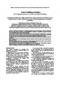
Figure 1. Wall sections: a – typical wall section; b – simple external wall cavities; c – complex orthogonal wall cavities with internal flow disruption element; d – complex curvilinear external cavity and e – complex external cavity with connection between the cavities.
airflow will act as thermal insulation in a manner similar to that of traditional building bricks/blocks (see Figure 1(a)). The current research examines the airflow behaviour on various simple forms, some of which are more open to the external environment (Figure 1(b)) and some that are more closed and include elements that act to obstruct the airflow (Figure 1(c)). Very complex cavity forms (Figure 1(d)) and cavity systems with internal ventilation (Figure 1(e)) were not examined in the context of this research. The wall sections presented in Figure 1 could be fabricated in a traditional fashion as standard tiles (see the broken division line in Figure 1). This will limit the possibilities in creating cavities and will allow only a small number of variations (each variation will need a specific mold). It is more likely, however, that fabricating the suggested type of tiles will rely upon emerging types of complex form fabrication such as computer numeric control (CNC) milling and 3D printing. In this case, advanced options such as complex form with cavities, parametric form variations and internal ventilation connections (as described in Figure 1(e)) are feasible. Nonetheless, it is important to understand in this context that there is a relationship between the surface area of a building envelope and the thermal conductivity of the envelope. High surface area causes higher thermal conductivity.
Developing the building envelope’s section The main part of this research examined the influence of various types of building envelopes’ complex geometries on airflow close to the wall. We tried to develop a section of a wall where airflow is reduced to a minimum in certain areas, thus creating a microclimate that behaves, in terms of thermal insulation, in a manner similar to air gaps in traditional building envelopes.
Figure 2.
Schematics of the wall cross-section.
Using internal air cavities inside walls or in building blocks is a common practice. To yield good thermal insulation, it is desirable to minimize the convective heat transfer from such cavities, since they are exposed, to some extent, to the outer flow field. To this end, we used two strategies; in the first one, the cavities are designed as areas of low flow velocity. The second strategy is to alter the boundary layer thickness along the wall’s outer skin in order to improve thermal insulation, since it is understood that the interaction between the flow inside the cavity and that at the outer field will change the boundary layer characteristics of the latter. Therefore, a successful design will ensure low velocities within the air cavities while thickening the outer boundary layer. To quantify this interaction, the flow field was numerically simulated using the commercial software package Ansys Fluent V14. The following solver settings were used: Viscous model – k-epsilon; Realizable; Enhanced Wall Treatment; Pressure Gradient Effects; Scheme – Coupled; Pressure – Second Order; Momentum – Second Order Upwind; Turbulent Kinetic Energy – Second Order Upwind and Turbulent Dissipation Rate – Second Order Upwind. This study focuses on the flow field over several cavity shapes that were exposed to typical external velocity
Y.J. Grobman and Y. Elimelech
Downloaded by [Jacob Grobman] at 14:58 06 April 2015
4
Figure 3. Comparing the influence of various Vv /Vw ratios.
fields. Flow analyses were undertaken at three characteristic tangential velocities: 1 m/sec, 5 m/sec and 10 m/sec. In general, flow that impinges on a wall results in a stagnation region and tangential velocity regions. Since stagnation regions show almost no airflow and regions of tangential velocity are wider, we decided to restrict our mathematical
model to the external velocity field, which is tangential to the outer boundary of the wall. For simplicity, our analysis is two-dimensional: the characteristically high Reynolds numbers led us to work with a fully turbulent flow model, specifically and the use of the k-epsilon turbulence model. To facilitate comparison
Downloaded by [Jacob Grobman] at 14:58 06 April 2015
Architectural Science Review
5
(a)
(b)
(c)
(d)
(e)
(f)
(g)
(h)
Figure 4. Description of the cell shapes that were analysed. a–d show the basic shapes, while e–f depict shapes with an internal flow disruption element.
between several wall cross-sections, the volume of the void region inside each (Vv ) cell was kept to half the volume of solid wall cross-section (Vw ), i.e. Vv /Vw = 0.5. The width of each wall section is W (Figure 2). The selected ratio is similar to the Vv /Vw ratio of common building blocks. It is clear that examining different Vv /Vw ratios will probably have an effect on the airflow next to the building envelope. Moreover, it is expected to have a direct impact on the thermal behaviour of the wall, since it increases the area of the external surface of the envelope. An initial comparison between different Vv /Vw ratios (approximately 0.09 m/sec, 5 m/sec and 1.1 m/sec) for a circular shape shows that there is an increase in the average airspeed of 5 m/sec and 10 m/sec and a small decrease in average airspeed of 1 m/sec (see Figure 3).
Test cases Four different basic cell shapes were analysed to determine which cell shape would be optimal for future building envelopes. Since we could not find empiric information from earlier research on the behaviour of airflow next to building façades with cavities, we decided to start with basic geometric shape cavities. The basic cell shapes that were chosen for this stage included a rectangle, a triangle, a circle and a trapezoid. Each cell shape was tested both as is and after the insertion of an internal rib, resulting in eight different cell shape geometries (Figure 4). In all simulations in this stage of the research, we chose a wall thickness of 30 cm (Figure 5), which is one of
Figure 5. Schematic description of the mathematical domain and the relevant boundary conditions.
the typical widths used for load-bearing concrete walls in buildings. The wall consisted of 12 cavities one after the other in order to obtain a periodic solution. The 12 cavity segments were located far enough from the numerical domain inlet and outlet to minimize any numerical errors, which may be reflected from the outer boundaries of the mathematical domain. The boundary condition at the outer region, which was 770 cm away from the wall’s outer skin, is a slip wall in order to ensure the direction of the free stream velocity at that edge. The wall’s outer skin and that in the interface between the cell volume and the wall were simulated as a no-slip boundary (Figure 5).
6
Y.J. Grobman and Y. Elimelech (a)
(b)
(c)
(d)
Figure 6. Flow field over different cavity geometries at outer velocity of 1 m/sec.
Downloaded by [Jacob Grobman] at 14:58 06 April 2015
(a)
(b)
(c)
(d)
Figure 7. Flow field over different cavity geometries at outer velocity of 5 m/sec. (a)
(b)
(c)
(d)
Figure 8. Flow field over different cavity geometries at outer velocity of 10 m/sec.
Results The flow field over the four cavity geometries is presented in Figures 6–8. The background colour represents the total velocity, and the streamlines are represented by the black lines. For compactness, the flow field is presented over one period of the wall. A summary of the results is presented in Tables 1–3. Figure 9 presents flow fields over a flat wall that could be used as a baseline for the results with the façade with cavities. The results show that the flow velocity inside the cavities is remains low, although there are distinct differences between the four geometries. At an outer velocity field of 1 m/sec, cavity b is characterized by the lowest velocity
Table 1.
Airflow results summary. Shape a Shape b Shape c Shape d Average
1 m/sec 5 m/sec 10 m/sec Average
0.11 0.40 1.98 0.83
0.04 0.26 1.18 0.49
0.09 0.60 0.57 0.42
0.38 1.49 2.82 1.56
0.155 0.69 1.64 0.83
inside the cavity; furthermore, the outer boundary layer over this cavity is the thickest, denoted by the lowest velocity amplitude at the outer field (Figure 6). Similar results were obtained at an outer velocity of 5 m/sec. Cavity b is characterized by the lowest inner
Architectural Science Review
7
Table 2. Airflow results summary.
1 m/sec 5 m/sec 10 m/sec Average Table 3.
Shape e (a)
Shape f (b)
Shape g (c)
Shape h (d)
Average
0.11 0.35 0.33 0.26
0.07 0.21 0.97 0.42
0.15 0.31 0.27 0.24
0.07 0.29 0.49 0.28
0.10 0.29 0.52 0.30
Average airflow results of the two lines of simulation.
1 m/sec 5 m/sec 10 m/sec Overall average – the average of both lines of simulation
Downloaded by [Jacob Grobman] at 14:58 06 April 2015
(a)
Shapes a and e
Shapes b and f
Shapes c and g
Shapes d and h
0.11 0.37 1.16 0.55
0.06 0.24 1.07 0.46
0.12 0.46 0.42 0.33
0.23 0.89 1.66 0.92
(b)
(c)
Figure 9. Flow field over flat wall at outer velocity of 1 m/sec (a) 5 m/sec (b) and 10 m/sec (c).
velocity amplitude, and the boundary layer thickness resembles that over cavity a (Figure 7). At an outer velocity of 10 m/sec, cavity c was characterized by the lowest inner velocity amplitude (Figure 8). It is interesting to see that although the inner velocity inside cavity b is not the smallest, the unique interaction between the inner and outer field creates the thickest boundary layer over the outer wall boundary, a fact that enhances thermal insulation despite the relatively high velocity inside the cavity itself. On average in all three air speeds, alternative c shows the best performance. However, in areas with very low air speed (not higher than 5 m/sec), alternative b would probably perform better (see Table 1). The next line of simulations examined the influence of a flow disruption element within the cavities that was expected to decrease even further the airflow speed inside the cavities. The results show that the flow velocity inside the cavities is significantly lower in comparison to the previous examination (0.3 m/sec as oppose to 0.83 m/sec). At an outer velocity field of 1 m/sec, cavity f (b with a flow disruption element) is characterized again by the lowest velocity inside the cavity. The outer boundary layer over this cavity is the second thickest but almost similar to cavity h (d with a flow disruption element), denoted by the lowest velocity amplitude at the outer field. However,
this time the differences between the different options are smaller. This could be attributed to the strong influence of the flow disruption element that was introduced in this second round of simulations (see Figure 10). Similar results were obtained at an outer velocity of 5 m/sec. Cavity f is characterized by the lowest inner velocity amplitude. Interestingly, the results in cavities e and f are similar to the previous simulation run without the flow disruption element while in cavities g (c with a flow disruption element) and h it is significantly lower. This could be explained by the influence of the angle of the shape in this wind speed. Moreover, although cavity h does not present the best results, it does show the largest decrease in air speed – about 5 times lower than in the simulation without the disturbance (see Figure 11). The results at an outer velocity of 10 m/sec show that cavity g is characterized by the lowest inner velocity amplitude while cavity e (a with a flow disruption element) yields the second lowest results. These results can be explained by the probable increasing significance of the size of the opening in high wind speeds. Repetitive opening without gaps such as cavity f probably behaves as a large opening. However, although cavity g has witnessed the largest increase in internal wind speed, it is still one of the two options with the thickest outer boundary layer.
8
Y.J. Grobman and Y. Elimelech (a)
(b)
(c)
(d)
Figure 10. Flow field over different cavity geometries with flow disturbance at outer velocity of 1 m/sec.
Downloaded by [Jacob Grobman] at 14:58 06 April 2015
(a)
(b)
(c)
(d)
Figure 11. Flow field over different cavity geometries with flow disturbance at outer velocity of 1 m/sec.
(a)
(b)
(c)
(d)
Figure 12. Flow field over different cavity geometries with flow disturbance at outer velocity of 10 m/sec.
Interestingly, the results of cavities e and g are almost similar to the results in 5 m/s that means that the increase of wind has almost no influence in these forms (see Figure 12). On average, alternative g shows the best performance. However, similar to the previous line of simulation without flow disturbance, in areas with low air speed (not higher than 5 m/sec) in the façade, alternative f would probably perform better. An average of both lines of simulation shows that shapes c and g present the best performance in terms of
reducing the airflow in the cavity. However, in scenarios with an air speed of 5 m/sec and below, shapes a, e, b and f perform better. In fact, in these external air speed scenarios, the internal air speed in shape b is about half as much as shape c and f (see Table 3).
Conclusions and future research The research presented here develops an initial framework for a shift towards using the geometry of the building envelope to create a microclimate on the building façade.
Downloaded by [Jacob Grobman] at 14:58 06 April 2015
Architectural Science Review The microclimate will be used to increase the building envelope’s thermal insulation, thus reducing the need for expensive insulating materials. In order to prove the potential of the proposed idea, four basic cavity shapes that generate different patterns of airflow were examined in fluid dynamic simulation. The simulation results show that the air speed was reduced significantly in all the cavities, thus creating a microclimate. Although the trapezoid-shaped cavity (shapes c and g) shows the best average results, the difference between these results and the results of the rectangular and triangular cavities is rather small (0.13–0.22 m/sec). It is not clear at this stage whether this difference is significant in terms of its influence on the microclimate’s performance and its relation to the building insulation. The simulation results also show that the introductions of flow disruption elements have a potential to impact airflow significantly, especially in high external air speed (5 and 10 m/sec). The influence of the tested flow disruption elements in low airspeed (1 m/sec) is inconclusive and depends on the cavity’s shape (shape d (circular) showed a decrease in airflow with the introduction of the disruption element, while the other shapes showed an increase in airflow). The next step of this research will involve 2D and 3D CFD simulations of air speed and heat flow in the wall section shapes discussed in the current stage and variations on these shapes according to the insight of this stage. It will try to answer the questions and fill the gaps that were raised by this stage, which include: (1) understanding the influence of the width of the opening on the flow in various wind speeds. (2) Generating more information on the connection between internal airspeed and the angle of the shapes borders. (3) Generating more information of the connection between the shape and the thickness of the outer boundary layer. (4) Examining the influence of different climate scenarios (with various wind regimes, temperature, humidity and sun radiation) on the behaviour of airflow and thermal properties of the suggested envelopes. Following this examination and the data it is expected to provide about the difference between the thermal behaviours of these basic forms, it will be possible to optimize even further the microclimate’s performance (minimizing the airflow in the cavities and increasing the boundary layer thickness). The future optimization could widen the scope of the examined formal direction in the design of cavities by studying various ratios of Vv /Vw and examining more complex arrays of singular forms or complex combinations of forms with or without interior connections (see, e.g., options d and e in Figure 1). CFD results probably give a good prediction of the behaviour of the suggested envelopes. However, prior to application by designers for practical design, it is necessary to validate these results using physical models. This
9
could be done in a wind tunnel that will confirm both the simulation wind speed and heat transfer results. Moreover, having achieved a similar level of thermal insulation to that of a traditional building façade by using microclimate, it would be possible to examine and optimize the cavities of the best-performing envelope section for other functions such as natural light, self-shading, water conservation and the cultivation of vegetation (green wall). The significance of the proposed approach lies in the centrality of the building envelope to the design, construction and performance of buildings. The resulting shift in the traditional concept of building envelopes could potentially improve the building’s overall energetic performance, decrease urban heat islands by allowing vegetation to grow over the envelope and reduce the infrastructure needed for handling rainwater. Disclosure statement No potential conflict of interest was reported by the authors.
ORCID Yasha J. Grobman
http://orcid.org/0000-0003-4683-4601
References Aydogan, Ahu. 2012. Building-integrated Active Modular Phytoremediation System. Rensselaer Polytechnic Institute. http://gradworks.umi.com/35/30/3530027.html. Badarnah, L., and U. Knaack. 2008. “Organizational Features in Leaves for Application in Shading Systems for Building Envelopes.” In I:87–96. WIT Press. doi:10.2495/DN080101. Badarnah, L., Y. Nachman Farchi, and U. Knaack. 2010. “Solutions from Nature for Building Envelope Thermoregulation.” In Design and Nature V: Comparing Design in Nature with Science and Engineering, edited by C. A. Brebbia and A. Carpi, 251–262. Southampton: WIT. doi:10.2495/DN100221. Gramazio, Fabio, and Matthias Kohler. 2008. “Towards a Digital Materiality.” In Manufacturing Material Effects: Rethinking Design and Making in Architecture, edited by Branko Kolarevic and Kevin Klinger, 1st ed., 103–118. Oxon: Routledge. Grobman, Yasha J., and Eran Neuman. 2011. Performalism: Form and Performance in Digital Architecture. 1st ed. Oxon: Routledge. Gruber, P., and S. Gosztonyi. 2010. “Skin in Architecture: Towards Bioinspired Facades.” In Comparing Design in Nature with Science and Engineering. Presented at the Design and Nature V, edited by C. A. Brebbia and A. Carpi, 503–513. doi:10.2495/DN100451 Hauer, Erwin. 2007. Erwin Hauer: Continua-architectural Screen and Walls. New York: Princeton Architectural Press. Hensel, Michael, Achim Menges, and Michael Weinstock. 2010. Emergent Technologies and Design: Towards a Biological Paradigm for Architecture. Oxon: Routledge. Kats, Greg. 2009. Greening Our Built World: Costs, Benefits, and Strategies. Washington, DC: Island Press. Knippers, Jan, and Thomas Speck. 2012. “Design and Construction Principles in Nature and Architecture.” Bioinspiration
10
Y.J. Grobman and Y. Elimelech
Downloaded by [Jacob Grobman] at 14:58 06 April 2015
& Biomimetics 7 (1): 015002. doi:10.1088/1748-3182/7/1/ 015002 Laver, J., D. Clifford, J. Vollen, and C. A. Brebbia. 2008. “High Performance Masonry Wall Systems: Principles Derived from Natural Analogues.” In Design and Nature IV, I vol., 43–52. WIT Press. doi:10.2495/DN080251. Oberndorfer, Erica, Jeremy Lundholm, Brad Bass, Reid R. Coffman, Nigel Dunnett, Stuart Gaffin, Manfred
Köhler, Karen K. Y. Liu, and Bradley Rowe. 2007. “Green Roofs as Urban Ecosystems: Ecological Structures, Functions, and Services.” BioScience 57 (10): 823–833. doi:10.1641/B571005. Yannas, Simos. 2004. “Adaptive Skins and Microclimates.” Plea 2004 – The 21th Conference on Passive and Low Energy Architecture, Eindhoven, The Netherlands, September 19–22.