MICROCONTROLLER BASED GESTURE RECOGNITION. SYSTEM ... The basic
working of the project is .... 8051- Micro-controller and embedded system using.
Journal of Engineering Research and Studies
E-ISSN0976-7916
Research Article
MICROCONTROLLER BASED GESTURE RECOGNITION SYSTEM FOR THE HANDICAP PEOPLE Bhavina Patel, Vandana Shah, Ravindra Kshirsagar
Address for Correspondence 1
Instrumentation and Control, 2Electronics and Communication,3Electronics Sarvajanik College of Engineering and Technology, Dr. R. K. Desai Marg, Athwalines, Surat. ABSTRACT “Speech” and “gestures” are the expressions, which are mostly used in communication between human beings. Learning of their use begins with the first years of life. In human communication, the use of speech and gestures is completely coordinated. Machine gesture and sign language recognition is about recognition of gestures and sign language using gloves. A number of hardware techniques are used for gathering information about body positioning; typically either image-based (using cameras, moving lights etc) or device-based (using instrumented gloves, position trackers etc.), although hybrids are beginning to come about. However, getting the data is only the first step. The second step, that of recognizing the sign or gesture once it has been captured is much more challenging, especially in a continuous stream. In fact currently, this is the focus of the research. KEYWORDS Include at least 5 keywords or phrases
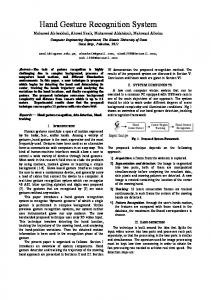
I. INTRODUCTION The data is analysed from an instrumented data glove for use in recognition of some signs and gestures. A system is developed for recognizing these signs and their conversion into speech. The results will show that despite the noise and accuracy constraints of the equipment, the reasonable accuracy rates have been achieved. The system objective was to develop a computerized Indian Sign Language (ISL) recognition system. The system considers only single handed gestures; therefore a subset of ISL has been selected for the implementation of Boltay Haath. The basic concept involves the use of computer interfaced data gloves worn by a disabled person who makes the signs. The computer analyzes these gestures, minimizes the variations and synthesizes the sound for the corresponding word or letter for normal people to understand. The basic working of the project is depicted in the following figure. The below diagram clearly explains the scope and use of the Boltay Haath system. The system aims at bridging communication gaps between the deaf community
and other people. When fully operational the system will help in minimizing communication gaps, easier collaboration and will also enable sharing of ideas and experiences. A. Performance Measures The following performance parameters were kept in mind during the design of the project: • Recognition time: A gesture should take approximately 0.25 to 0.5 second in the recognition Process in order to respond in real time. • Continuous and automatic recognition: To be more natural the system must be capable of Recognizing the gestures continuously without any manual indication or help for demarcating The consecutive gestures. • Recognition Accuracy: The system must recognize the gestures accurately between80 to 90 percent.
Figure 1.1 - System Diagram JERS/Vol. II/ Issue IV/October-December, 2011/113-115
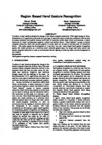
Journal of Engineering Research and Studies II. SYSTEM ARCHITECTURE The designed system input hand gestures to the system through an electronic sensor glove and it identifies the gesture patterns via microcontroller network. Then the identified sign is converted to text and then translated to voice output. The basic components of the Alltalk Wireless Sign Language Interpreter are given below: A. Modules for Gesture Input: Get state of hand (position of fingers, orientation of hand from glove and other sensors and convey to the main software. B. Data Transmission Module – Transmit all the data received from all sensors to the gesture processing module. C. Gesture Preprocessing Module – Convert raw input into a process-able format for use in pattern matching. In this case, scaled integer values ranging from 0 to 255. Gesture Recognition Engine – Examines the input gestures for match with a known gesture in the gesture database. III. GESTURE INPUT
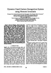
Figure 3.1 - Gesture Input Position and orientation of hand is obtained by two main parts; data glove and sensor arm cover. Data glove consists of 5 potentiometer as shown in Figure 3.1. Bend of the five fingers can be measured by potentiometer. A. ISL Signs Used In Boltay Haath: The sign language into Sub-domains that is English. This is because of the similarity of some gestures. Moreover English contain gestures of words and letters. Gestures have been categorized into Dynamic and Static. In English there are 26 letters.
Figure 3.2 - Equivalent English cue symbols for Database JERS/Vol. II/ Issue IV/October-December, 2011/113-115
E-ISSN0976-7916
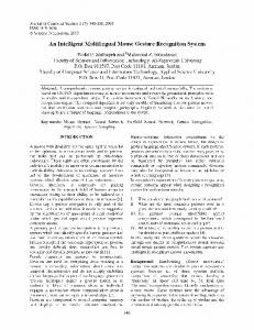
In which two are dynamic and words are of both types one-handed and two-handed. ISL also contains domain specific signs for example computer terms, Environmental terms and Traffic terms. Below figure 3.3 shows the block diagram of microcontroller 89C51 used for the proposed system.
Figure 3.3 –Block diagram of 80C51 IV. INTERFACED DEVICES A. ADC0808/ADC0809 The ADC0808, ADC0809 data acquisition component is a monolithic CMOS device with an 8bit analog-to-digital converter, 8-channel multiplexer and microprocessor compatible control logic. The 8bit A/D converter uses successive approximation as the conversion technique. The converter features a high impedance chopper stabilized comparator, a 256R voltage divider with analog switch tree and a successive approximation register. The 8-channel multiplexer can directly access any of 8-single-ended analog signals. The device eliminates the need for external zero and full-scale adjustments. Easy interfacing to microprocessors is provided by the latched and decoded multiplexer address inputs and latched TTL TRI-STATE outputs. The design of the ADC0808, ADC0809 has been optimized by incorporating the most desirable aspects of several A/D conversion techniques. The ADC0808, ADC0809 offers high speed, high accuracy, minimal temperature dependence, excellent long-term accuracy and repeatability, and consumes minimal power. These features make this device ideally suited to applications from process and machine control to consumer and automotive applications. For 16channel multiplexer with common output (sample/hold port) see ADC0816 data sheet. (See AN-247 for more information.)
Journal of Engineering Research and Studies B. MULTIPLEXER TABLE I: ANALOG CHANNEL SELECTION
The device contains an 8-channel single-ended analog signal multiplexer. A particular input channel is selected by using the address decoder. Table 1 shows the input states for the address lines to select any channel. The address is latched into the decoder on the low-to-high transition of the address latch enable signal C. 10 K Digital Potentiometer A digital potentiometer functions in the same manner as an analog potentiometer. It contains two end terminals and a movable wiper that changes the amount of resistance. However, the digital potentiometer also contains pins that are used to control the position of the wiper – as opposed to an analog knob or dial. The most common way to wire a digital potentiometer is to connect one end terminal to circuit ground and connect the other end terminal and wiper between a power source and an output component, such as a light emitting diode (LED). Because digital potentiometers range in complexity, the best learning strategy is to begin with a basic digital potentiometer that requires minimal connections. A potentiometer is a variable resistor that is most commonly used as a volume control in consumer electronics. It usually has three connection pins and the amount of resistance can be controlled by turning a knob, dial or screw. For a 10k (10,000 ohms resistance) potentiometer, the amount of resistance can be adjusted from nearly zero ohms to around 10,000 ohms. A potentiometer is a very useful component because you can also vary the amount of voltage and current going through it by varying the amount of resistance. Potentiometers consist of a resistance track with connection at both ends and a wiper which moves along the track as the spindle is rotated. It is an electrical device which has a user adjustable resistance. It can as a variable voltage divider. A potentiometer is constructed using a flat graphite annulus (ring) as the resistive element, with a sliding contact (wiper) sliding around this annulus. The wiper is connected to an axle and, via another rotating contact, is brought out as the third terminal. On panel post, the wiper is usually the center terminal. The modern potentiometer can be used as a potential divider (or voltage divider) to obtain a JERS/Vol. II/ Issue IV/October-December, 2011/113-115
E-ISSN0976-7916
manually adjustable output voltage at the slider (wiper) from a fixed input voltage applied across the two ends of the pot.
Fig. 5.1 A typical potentiometer FUTURE ENHANCEMENT • Designing of wireless transceiver system for “Microcontroller and Sensors Based Gesture vocalizer”. • Designing of a whole jacket, which would be capable of vocalizing the gestures and movements of animals. • Virtual reality application e.g., replacing the conventional input devices like joy sticks in videogames with the data glove. • The Robot control system to regulate machine activity at remote sensitive sites. VI. CONCLUSION This research paper describes the design and working of a system which is useful for dumb, deaf and blind people to communicate with one another and with the normal people. The dumb people use their standard sign language which is not easily understandable by common people and blind people cannot see their gestures. This system converts the sign language into voice which is easily understandable by blind and normal people. The sign language is translated into some text form, to facilitate the deaf people as well. This text is display on LCD. REFERENCES V.
1.
2.
3.
4. 5.
6.
R.S Pressman, Software Engineering: A Practitioner’s Approach, Fourth Edition, McGrawHILL International, 1997. Srinivas Gutta, Jeffrey Huang, Ibrahim F. Imam, and Harry Wechsler, “Face and Hand Gesture Recognition Using Hybrid Classifiers”. Seong-Whan Lee, “Automatic Gesture Recognition for Intelligent Human-Robot Interaction” Proceedings of the 7th International Conference on Automatic Face and Gesture Recognition. 8051- Micro-controller and embedded system using assembly and C “MUHAMMAD ALI MAZIDI”. IEEE conference on Automatic Face and Gesture Recognition, 2006. FGR 2006. Automatic gesture recognition for intelligent human-robot interaction. IEEE conference on Intelligent Transportation Systems, 2004. Recognition of arm gestures using multiple orientation sensors: gesture classification.