Microfluidic DNA extraction using a patterned aluminum oxide membrane Jungkyu Kim* 1, 3 and Bruce K. Gale1, 2, 3 1
Department of Bioengineering, University of Utah, Salt Lake City, UT 84112 Department of Mechanical Engineering, University of Utah, Salt Lake City, UT 84112 3 Utah State Center of Excellence for Biomedical Microfluidics, Salt Lake City, UT 84112 2
ABSTRACT A DNA extraction system was designed and fabricated using an AOM (aluminum oxide membrane) with 200 nm pores and PDMS microfluidic channels. The membrane was patterned using soft lithography techniques and SU-8 photolithography on the membrane. After making the pattern with SU-8, the AOM was observed using an SEM (scanning electro microscope) to verify the AOM structure was not damaged. From the SEM images, the AOM structure was not different after modification with SU-8. To complete the system, a PDMS mold for the microfluidic channels was made by soft lithography. Using the SU-8 mold, PDMS microchannels were cast using PDMS with a low polymer to curing agent ratio to provide adhesion between the patterned membrane and microfluidic channel. Then, the patterned membrane was sandwiched between PDMS microfluidic channels in a parallel format. The completed system was tested with 10ug of Lambda DNA mixed with the fluorescent dye SYBR Green I. Following DNA extraction, the surface of each well was examined with fluorescence microscopy while embedded in the microfluidic system. Extracted and immobilized DNA on the AOM was observed in almost every separation well. This microsystem, referred to as a membrane-on-a-chip, has potential applications in high-throughput DNA extraction and analysis, with the possibility of being integrated into polymer-based microfluidic systems. Keyword: DNA extraction, patterned AOM, microfluidic, membrane-on-a-chip
1. INTRODUCTION Aluminum oxide membranes (AOM) having 200 nm hexagonally arranged pores have the potential for numerous applications in the rapidly developing nanotechnology field including: imprinting, nanowire and nanotube templates. [13] As an example, a silane treated nanoporous alumina membrane was used as a nanowire template by first depositing gold particles in each pore. After this process, the membrane that used for the template was dissolved in a NaOH solution and either nanoparticles or nanotubes were made successfully. [2-3] The other applications of aluminum oxide membranes are biologically related. Filtration or separation of biological samples such as DNA, protein and plankton is possible as well as the use of the scaffold for cell culture.[4-5] Originally, the alumina ceramic was used as an implant to enhance adhesion at bone-implant interfaces.[6-7] Beginning with this concept, research about the cell response to nanopores was started and aluminum oxide membranes were used as cell culture templates with nanopores. Cells cultured on anodized nano-porous membranes show good proliferation and adhesion. [8-9] Another application of the membranes has been in biological sample preparation including polymerase chain reaction (PCR) amplification of DNA. DNA extraction for PCR or other analysis steps is one of the most important steps in many of bioanalytical systems. Conventional extraction procedures are labor-intensive and time-consuming, to overcome these drawbacks, a number of researchers have developed novel sample preparation methods that include expensive automated sample preparation systems and microchip type extraction system.[10-13] Aluminum oxide membranes have a uniform pore size, are rigid with low autofluorescence, and have a porosity of 50%. These characteristics have proven useful in filtration, where sample purification has been demonstrated with human blood to extract genomic DNA in large scale wells. [14-16] Generally, a two-step anodization process is used to make the aluminum oxide membranes. These processes need an expensive facility and time to produce the membranes. As a result, most research groups use commercially available AOMs, such as those distributed by Whatman, Inc. [17]. Moreover, if only part of the AOM is used, or different portions of the membrane are to be used for different separation processes, then the membrane must be cut to size. However, the
cutting process must be performed with a laser to avoid crack formation and propagation that occurs with conventional blade-based cutting methods. As such, our research group has developed a method of patterning the membrane with SU8 (MicroChem) to create discrete ports for DNA separation and have fabricated a DNA extraction chip based on this method.
2. FABRICATION PROCEDURE To produce a patterned aluminum oxide membrane, the anodic 45 AOM from Whatman Inc was used. In its received state, this membrane is very thin and brittle, so it is very hard to fabricate any structures on the membranes. To make a pattern with SU-8 on the membrane, a special holder for the AOMs was made of plastic using a traditional milling process. The holder consists of a series of closely-spaced, radially-oriented channels which extend from the outer edge of the membrane to the edges of the holder (see Fig. 1). The structures between the channels fully support the membrane, while allowing spun material that passes though the membrane to be removed by centrifugal force. To ease removal of the membrane from the supporting structure, a tip structure was made. The tip structure was very effective in handling the brittle membrane, and made breakage a less common occurrence. To keep the membrane to the supporting holder a PDMS ring cover was fabricated using an SU-8 mold. For making the PDMS film cover, a 3-inch silicon wafer was used to create an SU-8 mold. The wafer was heated for 5 minutes at 200ºC to drive water off the surface. After the wafer had cooled, SU-8 50 was spun on at 400 rpm for 30 seconds to produce a 300µm thick layer. The wafer was soft-baked at 65ºC for three minutes and 95ºC for six hours to remove the solvent. Then, the wafer was cooled at room temperature in preparation for exposure. Exposure of the wafer was carried out with a 365 nm EV-420 light source aligner (Electronic Visions Inc.) with a 1000 mJ/cm2 dosage. Post exposure baking was carried out for three minutes at 65ºC for 3 minutes and 95ºC for 15 minutes to complete the crosslinking of the exposed structures. The wafer was developed in PGMEA (propylene glycol monomethyl ether acetate) from Microchem with gentle shaking for 20 minutes, washed with isopropyl alcohol and dried with a nitrogen spray.[18] To prevent the PDMS from bonding to the native oxide present on the patterned silicon wafer, a fluorosilane compound (Gelest) was deposited onto the SU-8 mold in a vacuum chamber for two hours prior to casting the PDMS mold. PDMS was used as provided from the manufacturer (Sylgard 184®, Dow Corning,WI), with a base resin to curing agent ratio of 10:0.7 instead of the recommended 10:1 ratio to make it sticky PDMS. This stickier PDMS polymer was chosen to provide adhesion between the cover and base of the membrane holder. Before starting the curing stage, the liquid-type PDMS was placed under vacuum for one hour to remove any air bubbles. After this process, liquid PDMS was poured on the mold and put in a 65ºC oven for one hour to cure the PDMS. The PDMS film was peeled off slowly and trimmed around the inner circle to ensure a complete bond. After completing the PDMS cover, the support, membrane, and cover were stacked as shown in Fig. 1. When the membrane was stacked on the special holder, the centers of both were aligned as far as possible. The center alignment has an effect on the thickness uniformity of the pattern. The other important thing is to make small cuts in the plastic ring holding the membrane to protect from breakage during thermal cycles. During the soft bake and post exposure bake process, this plastic ring has more thermal deformation than the other structures have, so gaps provide some stress relief. The membrane can break easily due to differences of thermal deformation among the stacked materials, so the plastic ring attached to the membrane was made with small cuts with scissors before stacking all of the components. Once the membrane was affixed to the holder, a SU-8 lithography process was used to make the pattern on the aluminum oxide membrane. The mask for the lithography was made by xurography technique, or a knife plotter. Rubylith® film was cut with a cutting plotter (FC5100A-75, Graphtec Inc) to make a shadow mask. It consists of a UV opaque red emulsion on clear polyester backing without an adhesive. [19] After making the pattern on the Rubylith, it was attached to the glass by electrostatic interactions. The well diameter patterned on the AOM was 500µm and microchannel width connecting the wells was 200µm. To pattern the membrane, SU-8 2015 was used due to its low viscosity and ability to flow down within the nanopores easily. The SU-8 was poured on the aluminum oxide membrane and spun at 1000 rpm to get the 25µm thickness. The rest of the process was similar to the SU-8 process described earlier except for the bake times. To determine the appropriate bake time, the membrane was exposed with a 250 mJ/cm2 dosage to ensure complete exposure and the thickness was measured. The bake time for succeeding patterned membranes was based on the measured thickness of the SU-8 on the original AOM. [18] After making the pattern on the membrane, the thickness uniformity was measured with stylus-type profilometry. A picture of a patterned membrane is shown in Fig. 2.
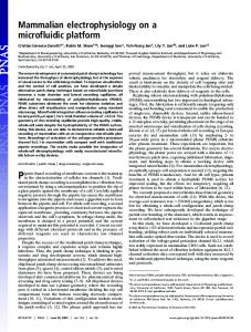
Fig 1. Specific holder for making the pattern on the membrane. (Top: PDMS cover, Middle: membrane, Bottom: Special holder )
Fig2. Patterned membrane with SU-8 2015. To minimize the thermal stresses and to align easily with the microchannel structures, the wells were fabricated using a ring and spoke configuration. The microfluidic system was made based on the concept of “single-input-multi-output” (SIMO) and an axisymmetric shape was used to generate a straightforward simulation model. To complete the system, microfluidic channels was made using soft lithography techniques. As mentioned before, a SU-8 mold was used to make the PDMS microfluidic structures. The pattern generated using SU-8 is shown in Fig. 3. To implement the 100µm by 100µm microchannels, SU-8 50 that is able to get the appropriate thickness with one spin coat was used to make the mold. With this mold, the PDMS microchannel structures were cast. The base resin and curing agent were mixed thoroughly in a 10 to 0.7 ratio to generate sticky PDMS for the same reason as mentioned before. To prevent the PDMS from bonding to the mold, the surface was treated using the fluorosilane compound. The liquid-type PDMS was baked at 65ºC oven for one hour with a syringe needle pressed through the PDMS to create inlet and outlet port structures. After completing the microfluidic structures, the patterned membrane was integrated with PDMS microfluidic structure by a simple compression bond. The bonding process was completed using the following process. The wells that existed on both the membrane and PDMS structures were aligned under the light field microscope and all structures were stacked with following sequence: PDMS microfluidic structure - patterned membrane - PDMS microfluidic structure. A complete DNA extraction system is shown in Fig. 4. Even though no leakage was observed using the sticky PDMS bonding method, a pair of transparent plastic sheets with a center-hole was used to clamp the layers together to prevent the leakage problem completely. Finally, the input and output connected to external fluidic components using a 20-gauge syringe needle.
Fig3. SU-8 mold for microfluidic structures and the structure for inlet and outlet vertical channels
Fig4. Left) Fully assembled microfluidic DNA extraction microsystem. Fight) vertical channel for packaging was made by using a molded rod structure.
3. EXPERIMENTAL SETUP To perform the DNA extraction experiments, several components beyond the completed microfluidic device were needed: a vacuum pump, buffer solution, DNA specific fluorescent dye, fluorescence microscope, and DNA. A vacuum pump with a 600 mbar capacity was connected to the outlet of the microfluidic system. The fluorescent dye SYBR green I was used to determine the presence and location of double-stranded DNA. The SYBR Green dye has a wide spectrum of application and its overall performance is excellent. It also has favorable photophysical properties such as negligible background fluorescence in the absence of DNA, temperature stability, selectivity for dsDNA, and high sensitivity, allowing the detection of as little as 1–2 ng of a synthetic 24-mer on 5% polyacrylaminde gels. [20-22] The SYBR green I used for this research is maximally excited at 497 nm, but also has secondary excitation peaks at ~290 nm and ~380 nm. The fluorescence emission of SYBR Green I bound to DNA is centered at 520 nm. [21] The DNA used for testing the extraction system was purified lambda DNA, which is commonly used as a substrate in restriction enzyme activity assays and for preparation of DNA molecular weight standards. The molecule is a linear double-stranded DNA (dsDNA), 48,502 base pairs in length. [23] The sample to be tested was prepared by mixing a buffer with 20µL of Lambda DNA (500ng/µL) and SYBR green I. To activate the SYBR green I, it was incubated at room temperature for 15 minutes. After these steps, this sample was connected through the inlet of the microfluidic system and the DNA mixed with SYBR green I was trapped on the AOM in the patterned well. To detect the extracted DNA on in the various wells, fluorescence microscope (IX 70, Nikon Inc.) with a band pass filter was used and the DNA was observed manually. The completed setup is shown in Fig. 5.
Fig 5. Experimental Setup for DNA extraction
4. RESULT AND DISCUSSION After pattering the membrane with SU-8, the thickness was measured to evaluate the uniformity of the SU-8 film with the stylus profilometer. The thickness was 29.33 µm when it was spun with 1000 rpm. For evaluating the thickness uniformity, 15 different locations were checked and the variation of thickness was 0.84µm. Using the AOM embedded in the SU-8 and PDMS microchannels, DNA extraction was tested and DNA was flowed through the patterned wells, fluorescence microscope examination showed successful DNA extraction onto the membrane surface without requiring disassembly of the device. No leaking was observed between ports. The SYBR Green I DNA dye was excited with blue light at a frequency of 497nm and fluorescence was detected at close to 520nm. This dye stain exhibits high affinity for dsDNA and a large fluorescence enhancement upon DNA binding. Before and after the extraction experiment, each well was checked with the fluorescence microscope. Most of wells produced similar green fluorescence, so four random wells are shown in Figure.6. Before the DNA extraction experiment, there was no fluorescence because the aluminum oxide membrane has minimal background fluorescence. After performing the DNA extraction, it was possible to detect the fluorescence clearly. After collecting fluorescence intensity measurements, the fluorescence images were analyzed with commercial image software (Image J). 10 wells were picked randomly and the intensity of the well before extracting the DNA was 25.21±1.1 out of 256 as a maximum value and the intensity value of the DNA in the extracted well based on the histogram generated in the software was 74.21±7.2 out of 256 as a maximum value. To get a higher uniformity of DNA extraction in each well, the microchannel size and shape have to be modified, which is currently being explored using
simulation tools. Testing of the patterned membrane has demonstrated successful extraction of DNA [Figure 6], even though the correlation between the DNA quantity and the fluorescence intensity has not yet been investigated completely. Since this microsystem is designed for extracting multiple samples simultaneously via the patterned wells on the membrane, the membrane was examined for cross-talk between wells. No evidence of leakage or cross-talk between wells could be found after testing individual wells one at a time. Using this method, it is possible to perform multiple extractions and multiple separations on a single aluminum oxide membrane, and this method can be applied to any other membrane requiring integration of the membrane into microchannel structures.
Fig 6. DNA extraction on the patterned membrane. A) Before extracting the DNA on the patterned membrane. B,C,D) After extracting the DNA on the patterned membrane,
5. CONCLUSION Using aluminum oxide membranes which have evenly distributed nanopores, permit high flow rates, and have no autofluorescence, the researchers demonstrated an appropriate system for DNA extraction in multiple wells simultaneously. The demonstration was implemented by integrating the AOM with PDMS microfluidic structure. The pattern on the membrane and microfluidic microchannels was made with modified soft lithography methods. After fabrication, these devices were integrated and tested with DNA samples. Florescence microscope images of the membranes after the DNA extraction tests showed that the DNA was trapped on the patterned wells successfully without leakage or cross-talk. From these results, we expect that a multichannel microfluidic DNA extraction can be implemented successful using this patterning technique on the membrane. If appropriate primers or sensing molecules were placed in each individual well, then multiple analysis protocols could be performed simultaneously on one sample, or the technique could be modified to perform the same analysis on multiple samples simultaneously. The technique can be used to make the development of multiple µ-TAS (Micro Total Analysis Systems) requiring the implementation of DNA extraction processes more likely, which is expected to result in inexpensive, high speed systems for diagnostics and sensing.
ACKNOWLEDGEMENTS The authors would like to acknowledge the financial support of the Utah State Centers of Excellence Program, ARUP, and the University of Utah.
REFERENCES 1. 2. 3. 4.
5.
6.
7.
8. 9. 10.
11. 12. 13.
14.
15. 16. 17. 18. 19.
Michal Lahav, Tali Sehayek, Alexander Vaskevich, and Israel Rubinstein, Nanoparticle Nanotubes, Angew. Chem. Int. Ed., 42, 5575, 2003 Y T Tian, G W Meng, T Gao, S H Sun, T Xie, X S Peng, C H Ye and L D Zhang, Alumina nanowire arrays standing on a porous anodic alumina membrane, Nanotechnology 15 189-191, 2004 Xinsheng Peng and Aicheng Chen, Electrochemical fabrication of novel nanostructures based on anodic alumina, Nanotechnology 15 743-748, 2004 Marc G. Elgort, M.G.H., Maria Erali,Jacob D. Durtschi, Karl V. Voelkerding, and Roger E.Smith, Extraction and Amplification of Genomic DNA from Human Blood on Nanoporous Aluminum Oxide Membranes. Clinical Chemistry, 50(10): p. 1817-1819, 2004 Cynthia H. McKenzie, Robert Helleur and Don deibel, Use of Inorganic Membrean Fitler (Anopore) for Epi fluorescence and scanning electron microscopy of Nanoplankton and Picoplankton, Applied and environmental microbiology, 58(2),773-776 ,1992 Yeonhee Kim, Jun-Hyeog Jang, Young Ku, Jae-Young Koak, Ik-Tae Chang, Hyoun-Ee Kim, Jae-Bong Lee and Seong-Joo Heo, Microarray-based expression analysis of human osteoblast-like cell response to anodized titanium surface, Biotechnology Letters 26, p. 399–402, 2004 Rachel L. Price, Luke G. Gutwein, Leonid Kaledin, Frederick Tepper, Thomas J. Webster, Osteoblast function on nanophase alumina materials: Influence of chemistry, phase, and topography, J Biomed Mater Res , 67(4), p128493, 2003 Karlsson M, Palsgard E, Wilshaw P R and Di Silvio L ,Initial in vitro interaction of osteoblasts with nano-porous alumina. Biomaterials 24 3039-46, 2003 Leary Swan E E, Popat K C, Grimes C A and Desai T A Fabrication and evaluation of nanoporous alumina membranes for osteoblast culture. Journal of Biomedical Material Research 72A 288-95, 2005 Maarten L.smit, B.A.J.G., Sandra G. Heil, Jacqueline A.M. Vet, Frans J.M. Trijbels and Henk J.Blom, Automated extraction and amplification of DNA from whole blod using a robotic workstation and an integrated thermocycler. Biotechnology Apl. Biochem., 32: p. 121-125, 2000 Harald H. Kessler, G.M.h., Evelyn Stelzl,Elisabeth Daghofer, Brigitte I. Santner, and Egon Marth, Fully Automated Nucleic Acid Extraction: MagNA Pure LC. Clinical Chemistry, 47(6): p. 1124-1126, 2001 Peter W. Laird, Alice Zijderveld, Koert Linders, Michael A. Rudnicki, Rudolf Jaenisch and Anton Berns, Simplified mammalian DNA isolation procedure, Nucleic Acids Research, 19 (15):p.4293, 1991 Michael C. Breadmore, Kelley A. Wolfe, Imee G.Arcibal, Wayne K. Leung, Dana Dickson, Branden C. Giordano, Mary E.Power, Jerome P.Ferrance, Sandford H. Feldman, Pamela M.Norris and James P. Landers, Microchip-based Purification of DNA from biological samples, Anal. Chem, 75 : p.1880-1886, 2003 Elgort M G, Herrmann MG, Erali M, Durtschi J D, Voelkerding K V and Smith R E ,Extraction and Amplification of Genomic DNA from Human Blood on Nanoporous Aluminum Oxide Membranes. Clinical Chemistry 50(10)1817-19, 2004 Kim J, Voelkerding K V and Gale B K ,Multi-DNA Extraction Chip Based on an Aluminum Oxide Membrane Integrated into a PDMS Microfluidic Structure. 3rd IEEE-EMBS Special conference on MMB p.5-7, 2005 Mihailescu G H, Pruneanu S, Neamtu S and Olenic L, Alumina membranes used as molecular filters for human red blood cells and bovine serum albumin. 2nd conference on Isotopic and Molecular process PM 62, 2001 Whatman Laboratory Div. 9 Bridewell Place, Clifton, NJ 07014 ,Product guide http://www.whatman.com/request_catalogue/12004.pdf , 2005 MicroChem, Manual for Negative Tone Photoresist Formulations, http://www.microchem.com/products/pdf/SU8_2002-2025.pdf, 2002 Daniel A. Bartholomeusz, Ronald W. Boutte, Joseph D. Andrade, Xurography: Rapid Prototyping of Microstructures using a cutting plotter. Journal of MEMS, submitted paper,2004
20. Vitzthum, F and Bernhagen, J ,SYBR green I: an ultrasensitive fluorescent dye for double-stranded DNA quantification in solution and other application. Recent Res. Develop Anal. Biochem. 2. 65-93, 2002 21. Haugland , R.P. 2001 Handbook of fluorescent probes and research chemicals, 8th edition. Molecualr proes, Inc. 22. Hubert Zipper, Herwig Brunner, Jurgen Bernhagen, Frank Vitzthum, Investigations on DNA intercalation and surface binding by SYBR green I, its structure determination and methodological implications. Nucleic Acid Research, 32(12) e103, 2004 23. Sanger F, Coulson A R, Hong G F, Hill D F and Petersen G B ,Nucleotide sequence of bacteriophage lambda DNA, J. Mol. Biol. 162 729-73, 1982
*
[email protected]; phone: 801-585-3176; fax: 801-585-9826; www.mems.utah.edu