Met. Mater. Int., Vol. 20, No. 5 (2014), pp. 923~928 doi: 10.1007/s12540-014-5018-6
Microstructure and Mechanical Properties of Nanostructured Bainite Weld with Regeneration 1,
2
1
1
1
1
K. Fang *, J. G. Yang , K. J. Song , X. S. Liu , Z. B. Dong , and H. Y. Fang 1
Harbin Institute of Technology, State Key Laboratory of Advanced Welding and Joining, Harbin, 150001, China 2 Zhejiang University of Technology, Institute of Process Equipment and Control Engineering, Hangzhou, 310032, China (received date: 18 September 2013 / accepted date: 27 December 2013) Because of the brittle martensite crystalline structure, nanostructured bainitic steel is very difficult to be welded and easily form cracks in the welded joint, which limits the scope of their application. Regeneration treatment can lead to nanostructured bainite formation in the welded joints, preventing further degradation of the welded joint. Detailed changes of microstructures and mechanical properties of the weld are characterized here. Coarse inter–dendrite structures appear in the weld due to welding segregation, and are confirmed to be retained austenite by TEM. Moreover, an extraordinary combination of strength and ductility of the weld is achieved. The ultimate tensile strengths are 1913MPa and 2115MPa when regeneration temperatures are 250 °C and 230 °C. The corresponding elongations are 5.14% and 2.3%. In addition, the tension fracture behaviour and crack propagation mode of the weld are investigated. Keywords: nanostructured materials, welding, phase transformation, microstructure, mechanical properties
1. INTRODUCTION Nanostructured bainitic steels have been developed with an ultimate tensile strength as high as 2.3 GPa and hardness in the range of 600-670 HV [1-4]. The properties are attributed to the mixture of ultra-fine scaled carbide-free bainitic ferrite and retained austenite crystalline strucutres. The bainite microstructure is commonly obtained by phase transformation at low temperatures (200-300 °C) in high-carbon silicon-rich steels. Phase transformation temperature of the bainite structure may be significantly reduced with carbon concentrations up to 0.8%. The lower bainite transformation temperature not only improves the bainite transformation fraction, but also reduces the size of bainite crystals to be nano-sized crystals [5,6]. With silicon content of about 2 wt% there is a suppression of the precipitation of carbides during bainite transformation, thereby eliminating crack initiation from the interface between carbide and matrix [7,8]. The remarkable properties of this structural material show great potential for many applications. However, industrial applications of this high-carbon nanostructured bainite are limited because of the material’s welding difficulty [9]. The conduction of the heat during welding into the adjacent material cre-
ates a low temperature heat-affected zone (LTHAZ). Many carbides may precipitate in the LTHAZ [10, 11], which leads to the decreasing of properties of welded joint. Further, the heat input will promote austenite crystals formation at high temperature heat-affected zone (HTHAZ) and fusion zone. The resultant austenite will lead to the formation of brittle martensite during the following rapid cooling process. It is this brittle martensite that may then cause cold cracking in the weld joint [12,13]. Our previous publication detailed a new regeneration method for welding nanostructure bainitic steel [13], which has been shown to strengthen the joint after welding. As the welded joint cools towards the bainite-start temperature BS, it is transferred into a furnace which is set at a temperature between BS and MS (martensite-start temperature). Afterward, the welded part is isothermally held in furnace to permit the bainite to grow again from austenite that is generated during welding process. In this paper, the microstructure feature in the weld is studied in detail to distinguish from that of base metal. The resulting changes of mechanical properties are analyzed. Moreover, the effect of regeneration temperature on mechanical properties of the weld is considered as well.
2. EXPERIMENTAL PROCEDURE *Corresponding author:
[email protected] KIM and Springer
The chemical compositions of nanostructured bainite steel
924
K. Fang et al.
Table 1. Chemical compositions of alloys investigated in the present work (wt%) C 0.82
Si 1.66
Mn 2.05
Cr 0.22
Mo 0.36
Ni 1.06
Al 0.051
Table 2. Welding parameters Welding current
Welding voltage
Welding speed
Shielding gas flow (Argon)
140A
20V
185 mm/min
12.5 L/min
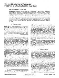
are listed in Table 1. The nanostructured bainite steel is prepared by isothermal transformation at 250 °C. Kinetic parameters BS=271 °C and MS=70 °C are calculated using thermodynamics software, MUCG83 [14]. Welding plate specimens are machined to dimensions of 2 × 40 × 100 mm. Bead-onplate welding with autogenous gas tungsten arc was performed along the centerline of these specimens. The welding parameters are listed in Table 2, which makes the welds full penetrated. The regeneration temperatures and time are 230/250 °C and 5 days, respectively. Microstructures are characterized by optical microscopy (OM), scanning electron microscopy (SEM, Quanta 200FEG), transmission electron microscopy (TEM, Tecnai G2-F30) and X-ray diffractometer (XRD, D/maxrB). The tensile properties of the weld are tested at room temperature on the Instron-5569 electronic universal experiment machine. Testing samples are sectioned longitudinally from the weld, as shown in Fig. 1. The total length is 50 mm. The length and width of the test area is 30 mm and 1 mm, respectively, and the thickness is about 2 mm (the thickness of welding plate). The elongation is measured by an extensometer with gauge length of 10 mm. In all the mechanical property tests, a crosshead speed of 0.1 mm/min is used.
Fig. 1. (a) Appearance of welding specimen, (b) the cross section of the welded joint.
3. RESULTS AND DISCUSSION 3.1. Microstructure observation Figure 1 is the image of welded specimen (Fig. 1a) and the cross section of the welded joint (Fig. 1b). No cracks are found, which confirms that the regeneration treatment can successfully avoid the cold cracks of this nanostructured bainitic steel. Figure 2 shows the microstructures of the weld regenerated at 250 °C. As it is expected, the weld is composed of columnar solidification structure. The microstructures at the dendrite boundaries differ from those in the core regions, which is mainly caused by segregation of alloy elements during welding solidification. It can be seen from the magnified views Fig. 3a that main microstructures in the weld are film-like structures (zone I), blocky structures (zone II) and coarse inte-dendrite structures (zone III). The coarse inter-dendrite structures are at the dendrite boundaries of columnar solidification structure. The microstructures in the base metal (Fig. 3b) only consist of film-like
Fig. 2. Scanning electron micrograph of the weld regenerated at 250 °C.
structures (zone I) and blocky structures (zone II). Figure 4 shows the typical TEM micrograph and corresponding electron diffraction patterns of film-like structures in base metal and the weld. The film-like structures are in nano-scale. Electron diffraction patterns show that the film-like structures are composed of α and γ, i.e., bainitic ferrite and retained austenite. Table 3 gives the approximate alloy element compositions of each structure in the weld by energy dispersive X-ray spectroscopy (EDS). It can be seen from Table 3 that the alloy elements of the film-like structures are almost the same as that of blocky structures. Therefore, it demonstrates that these alloy elements cannot diffuse at low regeneration temperature. Nevertheless, contents of alloy elements, especially Si, Mo and Mn, are
Microstructure and Mechanical Properties of Nanostructured Bainite Weld with Regeneration
925
Fig. 3. Magnified views of (a) the weld regenerated at 250 °C (b) base metal.
Fig. 4. Typical TEM micrograph and electron diffraction patterns of (a) base metal (b) the weld regenerated at 250 °C. Table 3. The alloying elements compositions of each zone in the weld (wt%) zone I zone II zone III
Si 1.97 2.14 3.45
Cr 0.37 0.28 0.54
Mn 2.09 2.14 3.91
Mo 0.56 0.78 2.10
Ni 0.85 0.82 0.90
much higher in the coarse inter-dendrite structures. This is because these alloy elements tend to segregate between dendrite arms during solidification. Carbon is excluded in Table 3 since routine EDS is not sensitive to this element. However, it can be seen from the EDS diagram (Fig. 5) that height of carbon peak in coarse inter-dendrite structures is lower than that in blocky structures. This indicates that the carbon content of coarse inter-dendrite structures is lower, compared with blocky structures. Theoretically, carbon content of coarse inter-dendrite structures is higher than that of core-dendrite structures after solidification because its equilibrium partition coefficient is lower than 1. However, the blocky austenite is enriched of carbon during bainite formation. As a result, the carbon con-
Fig. 5. EDS results for the weld regenerated at 250 °C of (a) zone II (b) zone III.
926
K. Fang et al.
ferrite. Using three peaks from each phase avoids biasing of the results owing to any crystallographic texture in the specimens. It can be seen that the volume fraction of retained austenite in the weld is lower than that of base metal, in spite that the bainite transformation of base metal and the weld were both held at 250 °C for 5 days. This is because during welding there is a loss of carbon in the weld [17-19]. The average carbon concentration in the fusion zone is 0.8% (by Direct Reading Spectrometry), which is 0.02% lower than base metal. The maximum fraction of bainitic ferrite can be calculated as: max
V Fig. 6. (a) Optical microstructure of the TEM sample in the weld regenerated at 250 °C, (b) TEM micrographs and electron diffraction patterns.
tent of blocky austenite becomes higher than coarse inter-dendrite structures. The differences of chemical compositions may affect the phase transformation process during regeneration treatment. Stabilized austenite in the coarse inter-dendrite structures is produced with a segregation of alloy elements, leading to fewer bainite crystals generating in this region, as shown in Fig. 3a. Untransformed austenite may remain as austenite or change into martensite [12,13,15]. Figure 6a shows the optical microstructure of the TEM sample. The coarse inter-dendrite structures are clear. The arrow indicates the coarse inter-dendrite structures for TEM observation. Figure 6b shows the TEM micrographs of the structures in the square as shown in Fig. 5a. It can be seen that the coarse inter-dendrite structures are very thick, making it difficult for electrons to penetrate them. This is due to the fact that the coarse inter-dendrite structures are difficult to etch compared to the film-like structures. Electron diffraction patterns show that the coarse inter-dendrite structures regenerated at 250 °C for 5 days remain austenite. This is an exciting result because austenite is beneficial to ductility than martensite in nanostructured bainite [1]. According to the analysis above, the regenerated weld shows a microstructure consisting only of bainite and austenite. The detailed microstructure variation between the weld and base metal has been investigated. Table 4 summarizes experimental data concerning the microstructure by XRD. The volume fraction of retained austenite is measured according to the method described in Ref. [16]. The retained austenite content is calculated from the integrated intensities of (200), (220) and (311) austenite peaks, and those of (200), (211) and (220) planes of
xT – x 0 = ---------------- xT – x
(1)
0
max
where V is the maximum fraction of bainitic ferrite, x is the average carbon concentration of the steel, x is the paraequilibrium carbon concentration of the ferrite and xT ' is the carbon concentration corresponding to T0' [20]. After welding, the average carbon concentration of the weld is lower than base metal, so the bainite fraction of the weld is higher than base metal. That is, the volume fraction of retained austenite is lower. Low carbon concentration will make bainite transformation much faster [21]. This is shown by comparing the structures of the weld and austenitised zone. Figure 7 shows the welded joint regenerated at 250 °C for 16 h. Bainite transformation in the weld is much faster than that in austenitised zone. The carbon content of austenite (Xγ) is calculated by the relationship between lattice parameter and chemical compositions as reported in Ref. [22]. The fraction of the remaining coarse austenite (VγC) is estimated by quantitative image 0
Fig. 7. Welded joint with regeneration at 250 °C with16 h.
Table 4. Experimental data concerning the microstructure of the weld and base metal base metal the weld
aγ (Å) 3.6223 3.6136
Cγ (wt %) 1.41 1.11
VF (%) 72.2 78.6
Vγ (%) 27.8 21.4
VγF (%) 16.9 11.2
VγC (%) 8.6
VγB (%) 10.9 1.6
Microstructure and Mechanical Properties of Nanostructured Bainite Weld with Regeneration
analysis using optical microscopy. It is then possible to estimate the fraction of thin film-like austenite (VγF) and blocky austenite (VγB) following Ref. [23]. The results are listed in Table 4. In this table, it is shown that austenite carbon content in the weld is lower than that of base metal. The weld exhibits a lower fraction of VγF when compared with the base metal, and therefore the fraction of blocky austenite is much lower. However, the remaining coarse austenite is 8.6% in the weld. This demonstrates that the microstructures in the weld may significantly differ from that of base metal, in spite of the same heat treatment. 3.2. Mechanical properties Regeneration-temperature dependence of engineering stress versus strain curves of the weld are tested at room temperature, as well as the base metal. The results are illustrated in
Fig. 8. Mechanical properties of the weld and base metal.
927
Fig. 8. Ultimate tensile strength (UTS) is 1877 MPa and total elongation (εT) is 7.53% for the base metal (obtained at 250 °C). On the contrary, the ultimate tensile strength and total elongation (εT) for the weld regenerated at 250 °C are 1913 MPa and 5.14%, respectively. It can be seen in Fig. 8 that the weld regenerated at 250 °C exhibits a lower elongation when compared with base metal. Elongation of nanostructured bainite is controlled by the fraction and the mechanical stability of retained austenite [24,25]. Mechanical stability of the remaining austenite during tensile testing is dependent on the carbon concentration and the exerted constraint [26,27]. By the above microstructure analysis, fraction of retained austenite in the weld is lower than base metal. Moreover, half of the remaining austenite in the weld is the coarse type austenite, which is more unstable than blocky and film-like austenite. As a result, the elongation of the weld is 70% of base metal. It also can be seen from Fig. 8 that the ultimate tensile strength (UTS) and total elongation (εT) for the weld regenerated at 230 °C are 2115 MPa and 2.3%, respectively. By comparing with that at 250 °C, it is found that as the regeneration temperature increases, the strength of the weld decreases, while the elongation increases. For nanostructured bainite, with transformation temperature increasing, the fraction of retained austenite increases [28-30]. Therefore, an increasing regeneration temperature can also lead to an increase in the fraction of remaining austenite in the weld. As a result, the elongation increases and the strength decreases simultaneously. Figure 9 presents typical tensile fractographs of the base metal and the weld regenerated at 250 °C. They are both composed of shear lips and a fiber region. As indicated, ductile
Fig. 9. Typical tensile fractographs of (a, b, c) the base metal (d, e, f) the weld regenerated at 250 °C.
928
K. Fang et al.
dimples are predominant in the fractures of both samples, revealing that the tension crack propagation is in a ductile fracture mode. However, the fraction of shear lip in the weld is lower than that of base metal. Further, the deepness and size of dimples of the weld are slightly smaller than that of base metal. Therefore, the elongation of the weld is inferior to base metal.
4. CONCLUSIONS (1) A coarse inter-dendrite structure is generated in the weld. It is confirmed to be austenite other than martensite by TEM. (2) The volume fraction and the carbon content of the remaining austenite in the weld are lower than that of base metal, despite that the bainite transformation temperature and time are the same. What is more, coarse retained austenite is the primary austenite in the weld, which is the most unstable austenite. It is the main reason that the elongation of the weld is only 70% of the base metal. (3) A remarkable combination of strength and ductility of the weld is obtained after regeneration treatment. Mechanical properties of the weld strongly depend on the regeneration temperature. The elongation has the same trends as regeneration temperature while the strength has an opposite change.
ACKNOWLEDGEMENTS The authors are grateful to H.K.D.H. Bhadeshia for the helpful discussions on microstructure analysis and sincerely acknowledge the project sponsored by the Scientific Research Foundation for the Returned Overseas Chinese Scholars, State Education Ministry.
REFERENCES 1. F. G. Caballero and H. K. D. H. Bhadeshia, Curr. Opin. Solid State Mater. Sci. 8, 251 (2004). 2. H. K. D. H. Bhadeshia, Proc. R. Soc. 466, 3 (2010). 3. F. G. Caballero and H. K. D. H. Bhadeshia, J. Phys. Coll., 112, 285 (2003) 4. H. K. D. H. Bhadeshia, Mater. Sci. Eng. A. 481, 36 (2008) 5. C. Garcia-Mateo, F. G. Caballero, and H. K. D. H. Bhadeshia, Mat. Sci. Forum. 500-501, 495 (2005). 6. Y. S. Choi, I. M. Park, J. H. Kim, K. M. Cho, and D. L. Lee, Met. Mater. Int. 11, 327 (2005).
7. W. C. Jeong, Met. Mater. Int. 9, 179 (2003). 8. K. H. Kim, J. S. Lee, and D. L. Lee, Met. Mater. Int. 6, 871 (2010). 9. K. Fang, J. G. Yang, D. L. Zhao, K. J. Song, Z. J. Yan, and H. Y. Fang, Adv. Mater. Res. 482-484, 2405 (2012). 10. F. G. Caballero, M. K. Millerb, and C. Garcia-Mateo, Acta Mater. 56, 188 (2008). 11. F. G. Caballero, H. K. D. H. Bhadeshia, and K. J. A. Mawella, Mater. Sci. Technol. 18, 279 (2002). 12. S. G. Hong, Proc. in: 63rd Annual Assembly & International Conference of the International Institute of Welding, p.47, Istanbul, Turkey (2010). 13. K. Fang, J. G. Yang, X. S. Liu, K. J. Song, H. Y. Fang, and H. K. D. H. Bhadeshia, Mater. Des. 50, 38 (2013). 14. H. K. D. H. Bhadeshia, Metal Sci. 16, 159 (1982). 15. F. G. Caballero, M. K. Miller, and C. Garcia-Mateo, Acta Mater. 58, 2338 (2010). 16. A. K. De, D. C. Murdock, M. C. Mataya, J. G. Speer, and D. K. Matlock, Scripta Mater. 50, 1445 (2004). 17. M. Rombouts, J. P. Kruth, L. Froyen, and P. Mercelis, CIRP Ann. Manuf. Technol. 55, 187 (2006). 18. R. L. Klueh and J. F. King, Welding J. 61, 302 (1982). 19. C. Zhang, X. Song, P. Lu, and X Hu, Mater. Des. 36, 233 (2012). 20. H. Matsuda and H. K. D. H. Bhadeshia, Proc. R. Soc. Lond. 460, 1710 (2004). 21. H. K. D. H. Bhadeshia. Ironmak. Steelmak. 23, 405 (2005). 22. D. J. Dyson and B. Holmes, JISI. 208, 469 (1970). 23. H. K. D. H. Bhadeshia and D. V. Edmonds, Metal Sci. 17, 411 (1983). 24. B. Avishan, S. Yazdani, and S. H. Nedjad, Mater. Sci. Eng. A 548, 106 (2012). 25. C. Garcia-Mateoa, F. G. Caballeroa, and T. Sourmail, Mater. Sci. Eng. A 549, 185 (2012). 26. H. K. D. H. Bhadeshia and D. V. Edmonds, Metall. Trans. 10, 895 (1979). 27. C. Garcia-Mateo and F. G. Caballero, Mater. Trans. 46, 1839 (2005). 28. M. Zhang, T. S. Wang, Y. H. Wang, J. Yang, and F. C. Zhang, Mater. Sci. Eng. A 568, 123 (2013). 29. H. Amel-Farzad, H. R. Faridi, F. Rajabpour, A. Abolhasani, Sh. Kazemi, and Y. Khaledzadeh, Mater. Sci. Eng. A 559, 68 (2013). 30. J. Yang, T. S. Wang, B. Zhang, and F. C. Zhang, Mater. Des. 35, 170 (2012).