to assume that contact forces arise only at the vertices of the contact region [18]. Thus, ..... (b) The center of mass of the object lies directly above the central fixel.
Algorithmica (1997) 19: 4–39
Algorithmica ©
1997 Springer-Verlag New York Inc.
Minimal Fixturing of Frictionless Assemblies: Complexity and Algorithms D. Baraff,1 R. Mattikalli,1 and P. Khosla1 Abstract. In many assembly tasks it is necessary to ensure the stability of a subcollection of contacting objects. To achieve stability, it is often necessary to introduce fixture elements (also called “fingers” in some work) to help hold objects in place. In this paper the complexity of stabilizing multiple contacting bodies with the fewest number of fixture elements possible is considered. Standard fixture elements of the type explored in previous single-object grasping work are considered, along with a generalized variant of fixture elements. Both form-closure (complete immobility of the assembly), and first-order stability (stability of an assembly in the neighborhood of a specific external force and torque on each body) are considered. The major result is that for three of the four combinations of fixture element varieties and stability considered, achieving an optimal solution (that is, finding a smallest set of fixture elements yielding stability) is NP-hard. However, for many fixturing problems it seems likely that suboptimal, yet acceptably small solutions can be found in polynomial time, and some candidate algorithms are presented. Key Words. Fixturing, Complexity, Stability, Assemblies.
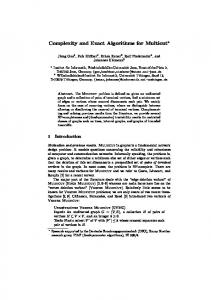
1. Introduction. Stability of bodies is an important consideration in planning an assembly sequence. While the problem of synthesizing stable grasps for a single object has received considerable attention [10], [11], [14], [22], [17], [13], stabilization of multiple bodies has only recently been a topic of interest [23], [15]. In the single-object case the emphasis has been on synthesizing a robust, stable grasp. Several different types of stability can be considered. A form-closure of an object is a grasp that completely immobilizes the object; equivalently, the object will remain motionless under any applied external force and torque. Less restrictive forms of stability might require the grasp to balance only a particular external force and torque, or a range of external forces and torques. Other forms of stability involving friction have been considered, but we defer frictional considerations to future work. In this paper we take on the task of stabilizing a collection of contracting rigid bodies without friction. We assume that we are given a collection of fixture elements which are sufficient to stabilize the entire assembly (Figure 1).2 Following Schimmels and Peshkin [19], and later Wolter and Trinkle [23], we use the term “fixel” to mean an immobile and rigid fixture element that exerts a frictionless point contact force on an object. In general the set of fixels available to stabilize the assembly is assumed to be a potentially very large collection; for example, the location of possible fixels might be generated by discretizing all exterior surfaces of the objects in the assembly. Further, we imagine that 1
Robotics Institute, Carnegie Mellon University, Pittsburgh, PA 15213, USA. This means of course that exceptional objects, as defined by Mishra et al. [17], are restricted from our consideration since they cannot be stabilized by any set of frictionless fixture elements.
2
Received May 24, 1994; revised January 6, 1995, and February 3, 1995. Communicated by J. S. B. Mitchell.
Minimal Fixturing of Frictionless Assemblies: Complexity and Algorithms
5
Fig. 1. (a) An assembly and its set of potential fixels. (b) The smallest set of fixels possible that stabilizes the assembly due to gravity, assuming object A is very massive. The seemingly odd fixturing on object B is because object A slides down and leftward, attempting to force object B to rotate counterclockwise.
every fixel has some nonnegative cost associated with it and that we would like to select an inexpensive subcollection of fixels that stabilizes the assembly. For example, the cost of a fixel might depend on: • Reachability. A fixel’s cost might indicate the relative difficulty in actually establishing the fixel at that specific point in space. Certain fixels would then be given a high cost because they occurred on regions of objects which were difficult to reach. • Fragility. There may be reasons to prefer not to fixture particular bodies in the assembly unless absolutely necessary. This could be indicated by making fixels that contact those objects expensive. • Constant cost. Every fixel might be equally expensive. If every fixel has unit cost, then a subcollection’s cost is simply its size. In this paper we are concerned with the last, and simplest, cost function—selecting the smallest possible fixel set that achieves stability (Figure 1). A lower bound for the complexity of selecting a minimal size stabilizing fixel set immediately establishes lower bounds for more general cost functions. A very different line of attack would be to generalize previous work on optimal grasps. For example, Kirkpatrick et al. [9] describe the measure of stability of a grasp based on a geometric interpretation of Steinitz’s theorem [17], [6]. Trinkle [22] similarly proposes a stability measure that can be computed in terms of a linear program, and then extends this work to measure and synthesize grasps (using, hopefully, a small number of fixels) for multibody assemblies. Similarly, Markenscoff and Papadimitriou [14] and Li and Sastry [11] also discuss what constitutes a good grasp for single-object assemblies, given a specific task in mind. We believe that these are all good criteria, and
6
D. Baraff, R. Mattikalli, and P. Khosla
should be extended to the case of multibody assemblies. However, before addressing these considerations, we believe that the issue of the number of fixels used to stabilize an assembly must be addressed. For single-object assemblies, this is often not a large concern, but for multibody assemblies, the size of the fixel set is clearly a factor to be considered. Although it is not clear that small fixel sets are in general good fixel sets, the existence and complexity of finding fixel sets of a specific size seems a reasonable starting point in considering multibody assemblies. Clearly, the size of the fixel set could be an important consideration when there are multiple fixturing sets yielding equally optimal grasps; in this case, one would probably be interested in the smallest such set. Accordingly, our goal in this paper is to establish lower bounds on the complexity of finding minimal fixel sets. Polynomial-time algorithms yielding suboptimal, but hopefully small, fixel sets are considered in Section 7.
2. Contacts and Fixels. In this paper we restrict our consideration to polyhedral objects. Thus, the contact regions between objects are always polygons (or degenerate polygons).3 Because we do not consider friction, in discussing stability it is sufficient to assume that contact forces arise only at the vertices of the contact region [18]. Thus, we assume that contact between objects can be characterized in terms of only finitely many contact points. At each contact, a surface normal is assumed to be well-defined. Vertex-to-vertex contacts and other degenerate contact geometries are not considered; Palmer [18] discusses the complexity issues that arise when normals are ill-defined. For illustrative purposes, we mostly consider planar systems of n objects. All of the results and algorithms in this paper are trivially extended to three-dimensional systems. We denote matrices and vectors using boldface type; the ith component of a vector b is the scalar bi , written in regular type. The symbol 0 denotes an appropriately sized vector or matrix of zeros. The notation b ≥ 0 indicates that bi ≥ 0 for all i. Given vectors b1 , b2 , . . . , bs ∈ Rr , the r × s matrix whose ith column is bi is written as [b1 b2 · · · br ]. Given matrices A ∈ Rr ×s and B ∈ Rr ×t , the notation [A | B] denotes the r × (s + t) matrix whose first s columns are the columns of A, and whose last t columns are the columns of B. Let n ∈ R2 be a force acting on a body at some point p ∈ R2 in a global coordinate system. The generalized force q ∈ R3 on the body due to n is q = (n, (p − c) × n), where c ∈ R2 denotes the body’s center of mass. If the net generalized force acting on body i is qi ∈ R3 , the generalized force for the entire collection of the n bodies is denoted by the vector Q ∈ R3n , where Q = (q1 , . . . , qn ). We refer to both q ∈ R3 and Q ∈ R3n as “forces”; which sort of quantity we are referring to should be clear from the context. 3
Actually, objects with curved surfaces can also be considered, as long as the resulting contact regions are polygonal. An example of a disallowed situation would be a cylinder resting upright on a plane, so that the contact region is a disk in the plane. Baraff [2] discusses the difficulties that arise in considering nonpolygonal contact regions.
Minimal Fixturing of Frictionless Assemblies: Complexity and Algorithms
7
Fig. 2. (a) A contact between two objects in the assembly. (b) Contact between an object and an immovable obstacle.
2.1. Contacts. Let the total number of contact points between bodies in an assembly be denoted Nc , and suppose that the ith contact occurs between bodies r and s at point p, with the surface normal n at p oriented as shown in Figure 2(a). The generalized force in R3 acting on body r is in the direction dr = (n, (p − cr ) × n), while the force on body s is in the direction ds = −(n, (p − cs ) × n). The direction of the generalized force on the entire collection of objects from the ith contact is therefore (s−1)−r
r −1
n−s
z }| { z }| { z }| { ui = (0, . . . , 0, dr , 0, . . . , 0, ds , 0, . . . , 0), where 0 ∈ R3 . The actual force Qi due to the ith contact has the form Qi = λi ui , where λi is a nonnegative scalar. The nonnegativity of λi arises from the restriction that contact forces be compressive. It is also necessary to represent predetermined mobility constraints; for example, parts of an assembly might be resting on an immovable table. We handle this by assuming that contact points can occur between some body r and some immovable obstacle (Figure 2(b)). The immovable obstacle is not considered one of the n bodies in our collection. In this case the force direction ui has the form r −1
(1) and, as before, Qi = λi ui .
n−r
z }| { z }| { ui = (0, . . . , 0, dr , 0, . . . , 0)
8
D. Baraff, R. Mattikalli, and P. Khosla
The net generalized force due to contact is simply the sum λ1 u1 + · · · + λ Nc u Nc , where all the λi ’s are nonnegative. For notational ease, we define the matrix U ∈ R3n×Nc as (2)
U = [u1
u2
···
u Nc ].
Any attainable net contact force can then be written in the form Uλ, where each component λi of λ ∈ R Nc is nonnegative. 2.2. Fixels. In stabilizing assemblies we consider two varieties of fixels. In previous single-object fixturing work, a fixel has been defined as a supporting, immobile finger that touches an object at a single point. A fixel on body r at location p produces a generalized force on the assembly in the direction r −1
(3)
n−r
z }| { z }| { v = (0, . . . , 0, d, 0, . . . , 0),
where d = (n, (p − cr ) × n) and n is the inward pointing surface-normal of body r at p (Figure 3(a)). We assume that fixels generate only compressive forces, so that the fixel force generated has the form αv for some nonnegative scalar α. Note that the force vector Q = αv generated by a fixel is very sparse, since a fixel produces a force on only a single body. Fixels, and the single-object contact occurring in Figure 2(b), appear to produce identical sorts of forces. Note however that the force due to contact in Figure 2(b) is always available to us, whereas the fixel force αv is available only if we have decided to select that particular fixel in stabilizing our assembly. A completely different variety of fixel arises if we are allowed to group some number of fixels together. Consider a set of k fixels, with the ith such fixel generating a generalized force in the direction vi ∈ R3n , with each vi being sparse, as in (3). The net force produced by the k fixels has the form λ1 v1 + · · · + λk vk , where the λ’s are all nonnegative. Thus, the set of forces produced by this group of fixels spans a k-dimensional space (assuming the vectors v1 through vk are linearly independent). Imagine though that the cost of using all k fixels is unit (even if some of those fixels turn out to be superfluous). We call such a grouping of fixels a clamp. A clamp may act on a single object (Figure 3(b)), or on two or more objects (Figure 3(c)). The reason for this terminology is because this generalization does in fact capture the concept of stabilizing an assembly by inserting mechanical clamps. Imagine that we have available to us gripping mechanisms which can be attached to a single object and achieve form-closure (complete immobilzation of that object). If we were interested in the minimum number of such mechanisms (that is, the minimum number of clamps) necessary to attain stability, we would count each clamp as having unit cost, no matter
Minimal Fixturing of Frictionless Assemblies: Complexity and Algorithms
9
Fig. 3. (a) An ordinary fixel. (b) A clamp, acting on a single object. If the clamp is selected, the object is completely immobilized. (c) A clamp acting on two different objects r and s, which are in contact. Selecting this clamp removes many, but not all, degrees of freedom from the two objects.
how many degrees of freedom the clamp actually eliminated. Note that the definition we have given for a clamp allows a clamp to apply to two or more objects, as in Figure 3(c). However, our complexity proofs concerning clamps are based on fixel groups that do in fact act on only a single body, as in Figure 3(b). Thus, we will show that the complexity of fixturing with clamps, as we have defined them, holds even if each clamp affects only a single body. 2.3. Fixel Forces. Given a set of Nf potential fixels we denote the direction of the force due to the ith fixel as vi ∈ R3n . If all the fixels are used in stabilizing the assembly, attainable fixel forces have the form α1 v1 + · · · + α Nf v Nf , where each αi is nonnegative. Accordingly, we define the matrix V ∈ R3n×Nf by writing (4)
V = [v1
v2
···
v Nf ].
Attainable fixel forces, using the entire set of fixels, have the form Vα, where α ∈ R Nf is a vector satisfying α ≥ 0. We are concerned with studying the forces attainable using only a subset of all the fixels. We denote a subset of the entire fixel collection as an index set F ⊆ {1, 2, . . . , Nf }. Given an index set F, if i ∈ F we say that the fixel set F contains the ith fixel. For a given fixel set F, only those fixels in the set can contribute to the total fixel force acting on the assembly. Let f i be the ith element of F, let k = |F|, and define the matrix V F ∈ R3n×k by (5)
V F = [v f1
v f2
···
v fk ].
10
D. Baraff, R. Mattikalli, and P. Khosla
(Without loss of generality, we may assume that f 1 < f 2 < · · · < f k .) The fixel forces attainable using only the fixel set F can then be written as V F α, where now α ∈ Rk and α ≥ 0. For clamps, almost the same notation can be used—the difference is essentially bookkeeping. In the case of fixturing with clamps, the matrix V is the matrix that would be obtained if each clamp was treated as a set of unrelated fixels. Thus, if the number P of fixels grouped to form the ith clamp is ci and there are r clamps, V contains ri=1 ci columns. Given a selection F of clamps, the matrix V F is obtained in a similar manner; the fixels comprising all the selected clamps are treated as completely unrelated, and used to form the columns of V F . Note that the number of columns of V F may depend on the specific set F, since V F will have |F| X
c fi
i=1
columns. Having defined the ways in which the fixel and contact forces can combine, we can proceed to introduce the various types of stability considered in this paper. Following that, we consider the complexity of finding fixel sets F of minimum size that achieve stability for a given assembly.
3. Types of Stability. In this paper we consider two different types of stability: formclosure and first-order stability. Form-closure is the stronger of the two, in that an assembly which is form-closed has no kinematically legal motions. An assembly which is form-closed is stable no matter what external forces are applied to objects in the assembly; thus, we can speak of form-closure without regard to the external force acting on an assembly. In contrast, first-order stability is a weaker form of stability than form-closure, and is defined relative to some external force. Trinkle [21] defines the concept of firstorder stability for a grasped frictionless object subject to gravity: if every kinematically legal virtual displacement of the object yields a strictly positive virtual increase in the gravitational potential energy, the object is said to be first-order stable. Trinkle also gives alternate characterizations of first-order stability in terms of the solution properties of various linear programs, while Wolter and Trinkle [23] extend the concept of first-order stability to multibody systems. Following Wolter and Trinkle [23], we can define first-order stability as follows. Given an assembly with a fixture set F, kinematically feasible virtual displacements δp ∈ R3n of the n bodies in the assembly are those δp that satisfy WT δp ≥ 0, where the wrench matrix W ∈ R(Nc +|F|)×3n is defined by W = [U | V F ]. If an external force Qext acts on the assembly, then a potential energy function U is defined for the T δp; that is, a virtual displacement δp of the system system by writing δU = −Qext
Minimal Fixturing of Frictionless Assemblies: Complexity and Algorithms
11
T yields a virtual potential energy change −Qext δp. Using this terminology, the concept of first-order stability is expressed as follows:
DEFINITION. An assembly with a fixel set F is first-order stable with respect to an external force Qext if, for all kinematically feasible nonzero displacements δp of the assembly, the corresponding change δU of the potential energy is strictly positive. Equivalently, T δp > 0 for all δp 6= 0 such that WT δp ≥ 0. −Qext 3.1. Directional Equilibrium. The importance of first-order stability in both [21] and [23] concerns the fact that first-order stable systems recover their original state when subject to suitably small perturbations. In this paper we have a very different emphasis: our concern is not perturbations of the objects, and the subsequent return of the assembly to its original state, but the stability of the assembly when the external force itself is perturbed. Accordingly, we are led to characterize first-order stability in a very different manner. We arrive at this characterization by defining directional equilibrium, which is even weaker than first-order stability: DEFINITION. An assembly with a fixel set F has directional equilibrium with respect to an external force Qext if the contact and fixel forces that arise in response to Qext sum to exactly −Qext resulting in a net force of zero on the assembly. Since our assemblies are frictionless and have well-defined contact normals at each contact point, the acceleration of an assembly in response to a given external force is unique [8], [5]. In particular, for any choice of Qext , directional equilibrium is easily determined.4 A simple result is that, for a frictionless assembly, if it is possible to attain contact and fixel forces which sum to −Qext , then in fact the contact and fixel forces will sum to −Qext [5], [1].5 If this is the case, then the external force −Qext is completely canceled, the net force on each body is zero, and no part of the assembly moves. Directional equilibrium with respect to a given Qext is therefore easily determined by seeing if the linear program (6)
Uλ + V F α + Qext = 0,
λ≥0
and
α≥0
possesses a solution α and λ. If this linear program has no solution, then the assembly is unstable and will begin moving under the external force Qext ; in this case, the actual motion can be determined by solving a quadratic program [12], [1]. An assembly with directional equilibrium can still be inherently unstable. Consider the assembly in Figure 4(a) consisting of a single object A in contact with an immovable horizontal surface. Potential fixels are indicated in the figure. If the external force applied to the system acts straight down upon A, then the assembly has directional equilibrium with respect to the external gravity force if we choose F = ∅. However, the slightest perturbation of the external force to one side or the other will cause the assembly to 4 Palmer’s [18] result that determining the stability of a frictionless system is NP-hard does not apply because of our assumption of well-defined contact normals. 5 This is not to say that the forces at individual contacts and fixels are well-determined: typically, these forces will be indeterminate. The net effect of the forces on bodies, however, will always be well-defined.
12
D. Baraff, R. Mattikalli, and P. Khosla
Fig. 4. (a) The assembly is in equilibrium without any fixels, but only if the external force is directed straight down. (b) The center of mass of the object lies directly above the central fixel. The assembly is in equilibrium using only fixel 2, but if gravity, or the object itself is perturbed slightly, fixels 1 and 3 are required.
move. A more extreme example is shown in Figure 4(b). In this case, given the fixel set F = {2}, the assembly has directional equilibrium with respect to a downward applied force through the center of mass. Now, however, either a perturbation in the direction of the external force or a perturbation in object B’s configuration (either a rotation or translation) unbalances the assembly. 3.2. Robust Directional Equilibrium. Directional equilibrium, by itself, is not a very practical concept in the context of fixturing (Figure 4). Accordingly, we define the notion of robust directional equilibrium, which turns out to be equivalent to first-order stability. DEFINITION. Given an external force Qext , we say a system with a fixel set F has robust directional equilibrium with respect to Qext if the assembly has directional equilibrium with respect to all external forces in some neighborhood of Qext . More precisely, there must exist a positive scalar ε such that, for all d ∈ R3n with kdk ≤ 1 (using any norm), the assembly has directional equilibrium with respect to the force Qext + εd. An assembly which has robust directional equilibrium can endure perturbations of Qext without becoming unstable. Thus, in Figure 4(b) the fixel set F = {2} induces directional equilibrium, but the set F = {1, 2, 3} is required for robust directional equilibrium. Note that the definition of robust directional equilibrium says nothing about how large a perturbation of Qext can be before stability is lost (Figure 5). Our proofs concerning robust directional equilibrium will show that minimal fixel sets yielding robust directional equilibrium are NP-hard to compute, even if the assembly can undergo large perturbations in Qext without becoming unstable. Note that the definition of robust directional equilibrium clearly subsumes the notion of mere directional equilibrium. As a practical matter, determining if an assembly with fixel set F has robust stability is no harder than seeing if the assembly has merely directional equilibrium. Borrowing from Mishra et al.’s [17] work on form-closure,
Minimal Fixturing of Frictionless Assemblies: Complexity and Algorithms
13
Fig. 5. The assembly has robust directional equilibrium without any fixels. The amount of perturbation in the external force required to make the assembly unstable can be made arbitrarily small by letting the angle θ be arbitrarily close to 180◦ .
we prove the following: THEOREM 3.1. Given an assembly with fixel set F, the assembly has robust directional equilibrium with respect to Qext if and only if: 1. The set of vectors {u1 , . . . , u Nc , v f1 , . . . , v f|F| } spans R3n (equivalently, the composite matrix [U | V F ] has rank 3n). 2. There exist strictly positive vectors α and λ such that Uλ + V F α + Qext = 0. PROOF. We begin by showing that the above two conditions are sufficient to establish robust directional equilibrium. Consider an assembly with fixel set F satisfying the two conditions of the theorem for a given external force Qext . Using any vector norm, let D be the set of vectors d ∈ R3n such that kdk ≤ 1. We must show that there exists ε > 0 such that the assembly has directional equilibrium with respect to Q + εd for all d ∈ D. However, since D is a closed and compact set, it will suffice to show that, for each vector d ∈ D, there exists ε > 0 such that the assembly has directional equilibrium with respect to Q + εd. From the first condition, there exists a solution αs and λs such that µ ¶ λs [U | V F ] = −d, αs or, equivalently, such that Uλs + V F αs + d = 0, although αs and λs will not necessarily be positive. From the second condition, there exist vectors λ and α satisfying Uλ + V F α + Qext = 0,
λ>0
and
Then, for some sufficiently small ε > 0, λ + ελs > 0,
α + εαs > 0,
α > 0.
14
D. Baraff, R. Mattikalli, and P. Khosla
and U(λ + ελs ) + V F (α + εαs ) + (Qext + εd) = (Uλ + V F α + Qext ) + ε(Uλs + V F αs + d) = 0. Thus, the assembly has directional equilibrium with respect to Q + εd. Conversely, consider an assembly with robust directional equilibrium with respect to a force Qext and let λ0 and α0 be nonnegative vectors such that Uλ0 + V F α0 = −Qext . To show that the first condition of the theorem holds, let b ∈ R3n be an arbitrary vector with kbk ≤ 1. Since the assembly is robustly stable, there exists ε > 0 such that Uλ + V F α = −(Qext + εb), but then Uλ + V F α = −(Uλ0 + V F α0 + εb). So U(λ + λ0 ) + V F (α + α0 ) = −εb, or, equivalently, −1
(λ + λ0 )
[U | V F ] ε = b. −1 (α + α0 ) ε Since b was arbitrary, rank ([U | V F ]) = 3n. To show that the second condition holds, let e denote the vector ei = 1 for all i; the dimension of e will vary according to its use. Let y ∈ R3n be defined by y = Ue + V F e. Then, for some ε > 0, there exist nonnegative λ and α satisfying Uλ + V F α = −(Qext + εy) = −(Qext + ε(Ue + V F e)), which yields U(λ + εe) + V F (α + εe) + Qext = 0. Since ε > 0 and e is strictly positive, both λ + εe and α + εe are strictly positive as well, and condition 2 is seen to hold. Based on Theorem 3.1, it is fairly simple to prove that the definitions given in this section for first-order stability and robust directional equilibrium are equivalent. Specifically, Appendix A proves the following theorem: THEOREM 3.2. Given an assembly with a fixture set F and an external force Qext , the assembly has robust directional equilibrium with respect to Qext if and only if the assembly is first-order stable with respect to Qext . As a consequence of this theorem, we can also characterize first-order stability in terms of the conditions of Theorem 3.1. Since Trinkle’s [21] work predates ours, and since the
Minimal Fixturing of Frictionless Assemblies: Complexity and Algorithms
15
phrase “robust directional equilibrium” is somewhat unwieldy anyway, we opt for the simpler “first-order stability” henceforth in this paper. As a practical matter, determining if a multibody assembly has first-order stability is easily accomplished, based on Theorem 3.1. First, the rank of the matrix [U | V F ] must be determined (say, by employing an SVD decomposition, or Gaussian elimination). Assuming that the matrix has rank 3n, linear programming can be employed to determine if the second condition of Theorem 3.1 holds. Although the strict positivity constraints on λ and α cannot be directly enforced in a linear program, we can work around this restriction; clearly, the magnitude of Qext has no bearing on the problem. We arbitrarily constrain all components of λ and α to be one or larger, by requiring λ ≥ e and α ≥ e. Letting s denote an unknown scalar, strictly positive vectors λ and α satisfying Uλ + Vα + Qext = 0 exist if and only if the linear program (7)
Uλ + V F α + sQext = 0,
λ ≥ e,
α ≥ e,
and
s ≥ 1,
possesses a solution for α, λ, and s. Additionally, following Wolter and Trinkle’s [23] discussion on robust fixture design, it is straightforward to determine if an assembly will be stable over an entire range of external forces. Given a set S of external force vectors, if the assembly has directional equilibrium with respect to each force vector in the convex hull of S, then the assembly has directional equilibrium with respect to every force vector in S, and is first-order stable with respect to all force vectors in the interior of the convex hull of S. 3.3. Form-Closure. The last form of stability we consider is form-closure, where the contact and fixel forces are sufficient to balance any and all external forces. DEFINITION. An assembly with a fixel set F has form-closure (or is form-closed) if the contact and fixel forces that arise in response to an external force Qext sum to exactly −Qext , for all Qext ∈ R3n . Form-closure of an assembly means that the assembly is completely immobile, and will not move in response to any force. Clearly, form-closure implies both directional equilibrium and first-order stability with respect to all external forces. Following the form of Theorem 3.1, and from Mishra et al.’s [17] work, the following theorem is easily proved: THEOREM 3.3. only if:
Given an assembly with fixel set F, the assembly is form-closed if and
1. The set of vectors {u1 , . . . , u Nc , v f1 , . . . , v f|F| } spans R3n . 2. There exist strictly positive vectors α and λ such that Uλ + V F α = 0. Once again, form-closure is easily detected by checking the rank of the matrix [U | V F ], and then seeing if the linear program (8) has a solution.
Uλ + V F α = 0,
λ≥e
and
α ≥ e,
16
D. Baraff, R. Mattikalli, and P. Khosla
Having formally defined these notions of stability, we can now consider the complexity of finding minimal stabilizing fixel sets. Following this, we consider algorithms for finding minimal stabilizing sets.
4. Size Bounds on F. For form-closure, work by Mishra et al. [17] and Markenscoff et al. [13] establishes that a single planar object always requires at least four fixels. However, given a predetermined set of fixels yielding form-closure, never more than six of those fixels are required for form-closure. For three-dimensional objects, those bounds are respectively seven and twelve. These bounds are obtained from the theorems of Carath´eodory and Steinitz [17], [6]. In particular, Steinitz’s theorem establishes that if Z ⊆ Rk and a point b ∈ Rk is in the interior of the convex hull of Z , then there exists a subset X ⊆ Z with at most 2k elements such that b is interior to the convex hull of X . In matrix parlance, this means that if µ ¶ λ [U | V] =b α for some strictly positive vector (λ, α) ∈ R Nc +Nf , then there exists a matrix M containing 6n or fewer of the Nc + Nf columns of [U | V] such that Mx = b for some strictly positive vector x. We can apply this result to planar multibody assemblies. If we take b to be the origin, 0, this gives us the result that never more than 2·3n = 6n contacts and fixels are necessary for form-closure. Similarly, if we take b to be a specific external force Q ∈ R3n , then, again, never more than 6n contacts and fixels are required for first-order stability with respect to any external force. In the other direction, both form-closure and first-order stability require a fixel set F such that the matrix [U | V F ] has rank 3n, and thus at least 3n columns. Because of this, both types of stability require a total of at least 3n contacts and fixels. For form-closure, this lower bound is improved to 3n + 1: if the matrix [U | V F ] has rank 3n and exactly 3n columns, it is nonsingular and the equation [U | V F ]y = 0 has only the single nonpositive solution y = 0. These lower bounds give us a lower bound on the size of the fixel set alone. Since both form-closure and first-order stability require rank ([U | V F ]) = 3n, we obtain 3n = rank([U | V F ]) ≤ rank(U) + rank(V F ) or equivalently rank (V F ) ≥ 3n − rank(U). Thus, at least 3n − rank(U) fixels are required to achieve form-closure. It is tempting to think that contacts always help to decrease the number of fixels needed for form-closure (or for first-order stability,
Minimal Fixturing of Frictionless Assemblies: Complexity and Algorithms
17
Fig. 6. An object with only translational freedom in contact with an immovable obstacle. The directions of the forces in R2 generated by the fixels are shown, as is the direction of the force generated by the contact. To positively sum these vectors to zero, vectors 1, 2, and 3 must all be used.
if the contacts are “underneath” an object) but this is not always so. For simplicity, consider a single object with only translational freedom, as shown in Figure 6. Without any contact, three fixels would be required for form-closure, but even though contact occurs, all three fixels are still required for form-closure. The direction of the contact and fixel forces in R2 are shown next to the object. Clearly, the only strictly positive sum of the vectors that is zero requires using vectors 1, 2, and 3. The use of vector C is not required. Although we will see that finding a minimal fixel set is in general hard, it is not difficult at all to find a fixel set of size 6n or less that imparts form-closure. We present such an algorithm below. We assume a predicate function positive-span(M, b) that takes a matrix M and a vector b and returns a value of TRUE if and only if there exists a vector x such that Mx = b
and
x > 0.
Note that x is required to be strictly positive. As discussed in Section 3, positive-span can be implemented as a linear program. The following algorithm returns a fixel subset F that achieves form-closure (assuming such a subset exists): Algorithm prune-fixels F = {1, 2, . . . , N f } for i = 1 to Nf do F 0 = F − {i} S = [U | V F 0 ] if rank(S) = 3n and positive-span(S, 0) = TRUE F = F0 done return F
18
D. Baraff, R. Mattikalli, and P. Khosla
Assuming that a fixel set F imparting form-closure exists, the fixel set found by the algorithm prune-fixel-set is guaranteed to be of size 6n or less. The correctness of the algorithm is a consequence of Steinitz’s theorem. If the set of Nc contacts and all Nf fixels can achieve form-closure, then no more than 6n of the fixels are required for form-closure. Initially, the fixel set F contains all the fixels, so F imparts form-closure. As the algorithm progresses, fixel i is removed from F only if it is demonstrated that the ith fixel is not required for form-closure. Thus, as long as F contains more than 6n elements, Steinitz’s theorem applies and there must exist some element of F that can be removed. As a result, the final set F returned must of size 6n or less. Clearly, the same algorithm can be used to find a set of 6n or less fixels that yields first-order stability with respect to an external force Qext . The exact same algorithm is used, except that positive-span(S, 0) is replaced by positive-span(S, −Qext ).
5. Complexity of Finding Minimal Fixel Sets. In this section we consider the complexity of fixturing with ordinary fixels; consideration of clamps is deferred until Section 6. Note that the problems of finding a minimal set of fixels or clamps for either first-order stability or form-closure are all in NP, since a candidate solution for any of the four problems can be tested by solving a linear program and computing the rank of a matrix. In this section and Section 6 we prove that, with the exception of finding a minimal fixel set yielding form-closure, the problems are all NP-complete. The complexity of finding a minimal fixel set yielding form-closure remains an open question which we consider further in Section 7. 5.1. A Naive Approach. One possible approach is to treat minimal fixturing problems with just fixels (and not clamps) as purely combinatorial linear algebra problems, ignoring the inherent sparse structure in the matrix V. Using the definition and theorems of Section 3, we could cast the problem of finding minimal fixel sets as combinatorial linear programming problems. As we show in this section, this approach would require us to solve NP-hard problems. Of course, this does not prove that minimal fixturing is NP-hard, in that we are treating V as general, when in fact it is not; however, this line of attack shows that a naive approach is not practical, and also furnishes some insights into the special case of fixturing a single body. For the special case of a single rigid body, there is no restriction on the fixel vectors {v1 , . . . , v|F| }; thus the matrices V that arise when fixturing a single body are in fact general. Since the largest minimal fixel set for a single planar object will always be no larger than six, a minimal fixturing set can found by an exhaustive search in time O(Nf6 ). For a single three-dimensional object, an exhaustive search could require up to O(Nf12 ) time. Although these complexity bounds are polynomial, a smaller upper bound would clearly be better (especially in fixturing three-dimensional objects). Since the matrices V that are encountered in fixturing a single body are general matrices (either of size 3 × Nf
Minimal Fixturing of Frictionless Assemblies: Complexity and Algorithms
19
or 6 × Nf ), the complexity results obtained in this section suggest that minimal fixturing for form-closure of a single object is likely to require exhaustive search. Suppose we consider the problem of finding a minimal fixel set yielding merely directional equilibrium with respect to an external force Qext . To find a minimal fixel set, we need to search for the smallest size set F that satisfies the conditions of (6). In the case where there is no contact, a fixel set achieves directional equilibrium if and only if there is a nonnegative solution α to V F α = Qext . If we pretend that the matrix V F is completely arbitrary, finding a minimal set F that yields directional stability is clearly equivalent to the following NP-complete problem [7, Section A6, Problem MP5]: Given a matrix M, an n-vector b, and an integer k < n, does there exist a vector x with no more than k nonzero components satisfying Mx = b and x ≥ 0? In our case, M would correspond to V, b would correspond to −Qext , and x would correspond to α. A similar sort of construction involving (7) shows that treating first-order stability as a general combinatorial linear algebra problem also results in an NP-complete problem. For form-closure of an assembly without contact, regarding the problem as a combinatorial linear algebra problem requires us to solve the following problem: What is the smallest set F such that rank(V F ) = 3n and V F α = 0 possesses a strictly positive solution α? Appendix B shows however that this problem is also NP-complete. 5.2. Finding Minimal Fixel Sets for First-Order Stability. Clearly, the naive approach to minimal fixturing for first-order stability by regarding V as a general matrix is impractical. As it turns out, even taking the special structure of V into account, the problem is still NP-complete. To prove this, we use the following NP-complete problem, known as the minimal set covering problem: Let A be a set A = {a1 , a2 , . . . , ar } of r elements. Let A1 through AS s be subsets of A. Does there exist a k-element subset Z ⊆ {A1 , A2 , . . . , As } such that z∈Z z = A? Given a set of elements A = {a1 , a2 , . . . , ar } and subsets A1 , A2 , . . . , As of A, we construct an assembly that can be stabilized with S k fixels if and only if there exists a set Z ⊆ {A1 , A2 , . . . , As } such that |Z | = k and z∈Z z = A. Without loss of generality, we assume that each subset Ai contains three elements; this restricted form of minimum set cover is still NP-hard. As a first step, we prove a result about the complexity of finding a minimal fixel set that yields directional equilibrium. We then augment this result to obtain a statement about minimal fixture sets that yield first-order stability. THEOREM 5.1. Given a vector Qext , and a set of fixels, finding a minimal subset of those fixels that yields directional equilibrium with respect to Qext (assuming such a set exists) is NP-hard.
20
D. Baraff, R. Mattikalli, and P. Khosla
Fig. 7. Objects 1 through r can only move downward; a downward external force acts on each of these objects. Objects r + 1 through r + s can move downward but are not subjected to an external force. An object r + j can be prevented from moving by selecting fixel j.
PROOF. The proof is by reduction of the minimum set covering problem. Given the set A = {a1 , a2 , . . . , ar }, and subsets A1 , A2 , . . . , As of A, we construct an assembly of r +s objects. Objects 1 through r correspond to the r elements of A. Contact constraints with immovable obstacles prevent the first r objects from any motion other than a translation straight down (Figure 7). The external force Qext acting on the system tries to accelerate each of these r objects downward. For each 1 ≤ i ≤ r , we say ai is covered when we have prevented object i from moving downward. Object r + j, for 1 ≤ j ≤ s, corresponds to the subset A j . These objects are also constrained so that they can only move vertically. The set of fixels for the assembly consists of s fixels. If the jth fixel is selected, then object r + j is prevented from moving downward (Figure 7). However, no external force (or rather, an external force of zero) acts on objects r + 1 through r + s. Thus, not all of these s objects necessarily need to be fixtured; in particular, if object r + j is not used to support any of the first r objects, object r + j can remain unfixtured. Each object r + j touches three other of the first r objects: if A j = {as , at , au }, then object r + j contacts objects s, t, and u. For example, the contacts on objects r + 1 and r + 2 in Figure 8 indicate that A1 = {a1 , a2 , a4 } and A2 = {a2 , a5 , ar }. Selecting fixel j prevents object r + j from moving downward, thus covering object i for all i such
Minimal Fixturing of Frictionless Assemblies: Complexity and Algorithms
21
Fig. 8. Contact between object r + j and object i occurs if and only if ai ∈ A j .
that ai ∈ A j . Conversely, if, for some i ≤ r , none of the fixels j satisfying ai ∈ A j are selected, then the external force will cause object i to move downward, consequently causing all such objects j to move downward as well. Clearly, then, a fixel set F that yields directional equilibrium with respect to the chosen Qext induces a covering set Z , by defining Z = {A j | j ∈ F}. Conversely, a covering set Z induces a fixel set yielding directional equilibrium6 by defining (9)
F = { j | A j ∈ Z }.
Since minimum covering is NP-hard, we conclude that finding a minimal fixel set yielding directional equilibrium is NP-hard as well. 6
A subtle point in this construction concerns the behavior of unfixtured objects. Suppose Z covers A, and F is defined by (9). Let A j 6∈ Z , so j 6∈ F and object r + j is unfixtured. Could some object i ∈ A j exert a force on object r + j, causing a downward motion? The answer to this is “no.” Since Z covers A, object j is covered and cannot move. If object i exerted a force on object r + j, object r + j would move away (downward), breaking contact with object i. The contact force at a point where contact is broken however must be zero [8].
22
D. Baraff, R. Mattikalli, and P. Khosla
As it stands, a set of fixtures yielding directional equilibrium will not necessarily yield first-order stability. Since the first r objects are acted upon by gravity, but objects r + 1 through r + s are weightless, the assembly may not be stable with respect to a perturbation of Qext . For example, if we choose a fixel set yielding stability that does not include fixel 1, then if Qext is perturbed so that a small downward force acts on object r + 1, that object will move downward. However, we can modify the construction of Figure 8 so that minimum covering sets Z correspond to minimal fixel sets F that yield first-order stability. In particular, the external force acting on the modified system will be an ordinary gravity field, acting on all the objects. A set of fixels yielding stability will do so for relatively large external force variations (for example, if gravity acts straight down on one object, but is inclined 15◦ with respect to another object). THEOREM 5.2. Given a vector Qext and a set of fixels, finding a minimal subset of those fixels that yields first-order stability with respect to Qext (assuming such a set exists) is NP-hard. PROOF. The proof consists of modifying the construction in Theorem 5.1 so that a minimal covering set Z yields a minimal fixel set F that is robustly stable with respect to a uniform gravity force. The modification is made in two steps. Let Qext be an external force acting downward on each object with strength proportional to an object’s mass. In the assemblies of Theorem 5.1, contact occurred between object i and object r + j if ai ∈ A j . We modify the constraints on objects r + 1 through r + s so that each object can now move only horizontally. The fixels are positioned so that selecting fixel j prevents object r + j from moving to the left. Contact between objects i and r + j is modified as shown in Figure 9. In order for object i to move downward, object r + j must move to the left. Clearly, selecting fixel j prevents object i from moving downward. Note however that if fixel j is unselected, the external force acting on object r + j induces no motion of object r + j. This modification does not change the fact that it is NP-hard to pick a minimal fixel set yielding directional equilibrium. This first modification overcomes the objection that the external force chosen for the previous proof was somewhat unnatural. Still, given a covering set Z , the corresponding F only induces directional equilibrium; any unfixtured object r + j is stable only because the external force points exactly straight down. A second modification fixes this. In Figure 10 the motion constraint on object r + j is altered so that the object can only move to the left and up (if unfixtured). If we assume that objects 1 through r are massive compared with objects r + 1 through r + s, then a fixel set which fails to cover some object i ≤ r does not yield stability. However, a fixel set F that yields directional equilibrium also yields first-order stability. To see this, suppose object r + j is unfixtured. Perturbations on the forces acting on fixtured objects are of no account. In order for object r + j to move, the external force acting on that object must be inclined a sizeable amount with respect to the negative vertical axis in order to cause a motion. Thus, a minimal covering set Z yields a minimal fixel set F yielding first-order stability. Although we are in general discussing planar configurations of objects, the construction shown in Figure 8 requires three dimensions, to allow for “crossovers” of objects in
Minimal Fixturing of Frictionless Assemblies: Complexity and Algorithms
23
Fig. 9. A downward force on object i results in a horizontal force on object r + j. The external gravity force acting on object r + j has no effect, as long as gravity points exactly downward.
the assembly. (Note however that each object in the assembly only requires one degree of freedom for its movement.) It is an open question as to whether or not truly planar constructions exists that are NP-hard to fixel. Unfortunately, we cannot follow Theorem 5.2 with a proof that finding a set of minimal fixels yielding form-closure is NP-hard; nor can be show that such a fixel set can be found in polynomial time. We show however that if an assembly’s contact graph (a graph where nodes are objects, and edges indicate contact between pairs of objects) is acyclic, a minimal fixel set is easily obtained in polynomial time. The complexity of the more general case of assemblies with cyclic contact graphs eludes us. Our strong suspicion however is that finding minimal sets of fixels yielding form-closure is not NP-hard. Before considering contact graphs, we consider the complexity of fixturing with clamps.
6. Complexity of Minimal Fixturing with Clamps. In this section we consider the complexity of stabilizing assemblies with a minimal number of clamps. Recall that clamps, which are groupings of fixels, give us the ability to form-close a single object with unit cost. If we consider assemblies where selecting a clamp causes a particular body to be immobilized, we see that determining a set of bodies that when immobilized yields stability of the entire assembly is a clamp-fixturing problem. Accordingly, we can show that fixturing with clamps is NP-hard by constructing assemblies where it is NPhard to determine the smallest number of objects whose immobilization yields stability for the entire structure.
24
D. Baraff, R. Mattikalli, and P. Khosla
Fig. 10. The constraints on object r + j are altered so that perturbations in the gravity direction have no immediate effect on object r + j.
The first theorem concerning fixturing with clamps is a trivial modification to the assemblies constructed in Figures 8 and 10. THEOREM 6.1. Given a vector Qext and a set of clamps, finding a minimal subset of those clamps that yields first-order stability with respect to Qext (assuming such a set exists) is NP-hard. PROOF. Consider Figure 10. We replace each fixel j with a clamp that form-closes body r + j when selected. Each such clamp has no more or less effect when selected than the original, single fixel. Thus, finding a minimal set of clamps required for first-order stability is just as hard as finding a minimal set of ordinary fixels. Although we have not obtained a result concerning ordinary fixels and form-closure, we can say something about the complexity of minimal fixturing with clamps for formclosure. Our proof involves a reduction from the following NP-complete problem [7, Section A1, Problem GT 7]: Let G = (N , E) be a directed graph with node set N and edges set E, and let k < |N |. Let the in- and out-degree of every node be two or less. Does there exist a subset of nodes N 0 ⊆ N with |N 0 | = k such that N 0 contains at least one vertex from every directed cycle in G? To perform the reduction we take a directed graph, all of whose nodes have both inand out-degree of two or less, and build a corresponding assembly. The assembly will
Minimal Fixturing of Frictionless Assemblies: Complexity and Algorithms
25
Fig. 11. (a) Starting from its initial position, node object A can never slide to the left. Similarly, the connecting rods B and C can never slide to the left. Object A’s input connecting rods can slide forward (to the right) only if object A can. (b) If object A is given a push from an input connecting rod, and object C cannot move, object A can move by sliding to the right and up. Conversely, if B could not move but C could, object A would slide to the right and down. If neither B nor C can move, then A cannot move either, preventing A’s input connecting rods from moving as well.
be form-closed by immobilizing k objects if and only if a subset N 0 of size k exists that contains at least one vertex of every directed cycle of the graph. The basic building block of the assembly is shown in Figure 11. We call object A a node object and objects B and C connecting rods. A node object corresponds to a node of the graph. Connecting rods represent edges, and run from the “output” side of a node (the right side) to the “input” side (the left side) of some other node. In Figure 11 the only freedom of motion for the connecting rods is to slide horizontally to the right. We say this is a “forward” motion of the connecting rod. Connecting rods are always prevented from moving “backward” (to the left) from their initial position because of their spurs. When can object A slide forward? Suppose that rod B is prevented from moving forward. Then object A could slide rightward and down only if the rod C is free to slide forward. Similarly, object A can slide to the right and up only if rod B is free to slide forward. If neither of the rods B and C can move, object A is prevented from moving as well. (Clearly, under no circumstances can object A slide to the left.) The construction
26
D. Baraff, R. Mattikalli, and P. Khosla
of Figure 11 is replicated for each node of a graph. The assembly corresponding to the graph
is shown in Figure 12. Consider object 1 in this assembly: as in Figure 11, object 1 can slide forward if and only if one or more of its connecting “output” rods can slide forward. (Connecting rods can be made to turn corners as shown in the upper-left detail of Figure 12. Similarly, nonplanar graphs can be formed by having a connecting rod cross over another rod by turning a corner out of the plane of the paper, and later turning back into the plane of the paper. For clarity, the spurs on the connecting rods preventing any “backwards” movement by the rods are not shown in Figure 12.) Since object 1’s connecting rods contact objects 2 and 4, object 1 can move if and only if one or both of objects 2 and 4 are free to move. In order to perform the reduction, we want a node object i to be able to move if and only if one or more of the node objects it is connected to can move. For example, object 1 can move if and only if object 2 or object 4 can move. Object 5 is connected to only one other node object, so an extra constraint is placed on object 5, preventing it from moving downwards at all. Clearly, object 5 can move if and only if object 3 can move. Since object 3 is connected to no other node objects, it is constrained to have no motion at all. Nodes with zero or one incoming edge (such as nodes 5 and 2) need no special treatment. Thus, given a directed graph G = (N , E) we construct an assembly. The assembly will have |N | node objects of the type shown in Figure 11, and |E| connecting rod mechanisms. (We will describe the set of clamps shortly.) A connecting rod mechanism is placed between node objects i and j for each directed edge (i, j) ∈ E, with the connector running “out” from object i and “into” object j. For each node in the graph with no outputs, additional constraints are added on the node object that immediately prevent it from moving (as illustrated by node 3 in Figure 12). For each node with only one output, an additional constraint is placed on the node object i (as illustrated by node 5 in Figure 12). The final assembly thus has the property that node object i can move if and only if, for some (i, j) ∈ E, node object j can move as well. Note that this implies that if node i has no outgoing edges, node object i can never move.
THEOREM 6.2. Given a graph G = (V, E), there is a movable node object in the constructed assembly if and only if there exist movable node objects n 1 , n 2 , . . . , n k such that (n i , n i+1 ) ∈ E for i < k and (n k , n 1 ) ∈ E.
Minimal Fixturing of Frictionless Assemblies: Complexity and Algorithms
27
Fig. 12. The assembly corresponding to the five node graph on p. 26. Connecting rods can bend around corners as shown in the detail in the upper left: assuming rod C can move to the right, moving rod A to the right causes rod B to move downward, causing rod C to move to the right. Nonplanar graphs (requiring edges to “cross over” each other) are modeled by having connecting rods turn corners taking them out of the plane of the assembly.
PROOF. The forward direction of the proof is obvious from the construction of the assembly: assuming the hypothesized list n 1 , n 2 , . . . , n k of movable objects, each of the k node objects in the list can be moved forward some small amount, if all the movements occur simultaneously. Conversely, suppose that node object n 1 in the assembly is movable. By construction, a node object is movable if and only if it is connected to another movable node object n 2 . Then there must exist a movable node object n 2 such that (n 1 , n 2 ) ∈ E. However, in order for n 2 to be movable, it too must be connected to some movable node n 3 such that (n 2 , n e ) ∈ E. Clearly, this argument can be continued, generating a list of movable nodes n 1 , n 2 , n 3 , . . .; but since there are only finitely many nodes, at some point we will encounter a movable object n j such that n i is already on the list. Then the subsequence n i , n i+1 , . . . , n j is a list of movable node objects satisfying the conditions of the theorem. Using Theorem 6.2, we can establish the complexity of establishing form-closure with a minimal set of clamps. THEOREM 6.3. Given a set of clamps, finding a minimal subset of those clamps that yields form-closure (assuming such a set exists) is NP-hard.
28
D. Baraff, R. Mattikalli, and P. Khosla
PROOF. Given a directed graph G = (N , E), we construct the corresponding assembly of Theorem 6.2. In addition, |N | clamps are added. The ith clamp, when selected, formcloses node object i. Given a set N 0 that contains at least one vertex from every directed cycle in G, the corresponding set of clamps F = {i | n i ∈ N 0 } induces form-closure. This follows from Theorem 6.2: the connecting rods cannot move unless some node object can move, and a movable node object implies a movable cycle of node objects. However, since at least one node object in every possible cycle of node objects is clamped, no object can move. By the same argument, a set of clamps F inducing form-closure yields a set N 0 = {n i | i ∈ F} containing at least one vertex of every cycle in the graph. As a result, minimal sets N 0 containing a vertex from each cycle correspond to minimal sets F yielding formclosure. As in Section 5.2 (Figure 8), it is an open question as to whether the reduction shown in Figure 12 truly requires three dimensions, to accommodate nonplanar graphs. Again, note that each object in Figure 12 requires only two degrees of motion freedom.
7. Algorithms. So far we have shown that for all but one of the fixturing/stability combinations considered, finding a minimal fixture set is NP-hard. The only exception has been finding a minimal set of ordinary fixels that yields form-closure. Although NPhardness results can often be cause for disappointment from an algorithmic standpoint, we do not believe this is the case here. 7.1. Degeneracy. From the theorems of Carath´eodory and Steinitz, we know that formclosure requires between 3n + 1 and 6n fixels and contacts. The pruning algorithm presented in Section 4 is a simple polynomial-time algorithm for finding a stabilizing set of not more than 6n fixels. However, 6n is the worst-case behavior of the algorithm—the algorithm may manage to prune the set of fixels to well below 6n. Characterizing the performance of the algorithm would require a characterization of the set of assemblies one wants to fixture; clearly, this is an application-dependent question. However, there is a simple insight into the lower and upper ranges of 3n + 1 and 6n contacts and fixels required to form-close an assembly. A similar insight applies to first-order stability. DEFINITION. A set of vectors Z ⊂ Rn is said to be degenerate if there exists a subset of n or fewer vectors of Z that is linearly dependent. Otherwise, Z is said to be nondegenerate. Chv´atal [3, Theorem 17.1, p. 265] shows that if z is a point in the convex hull of a set Z ⊂ Rn , then z is a strictly positive combination of not more than n + 1 points of Z . As a special case, if Z is nondegenerate and z is the origin, then in fact there must be a subset Y ⊂ Z of exactly n + 1 points that positively sums to zero (since if Z is nondegenerate, any subset of n or fewer vectors of Z is independent and cannot positively sum to zero).
Minimal Fixturing of Frictionless Assemblies: Complexity and Algorithms
29
The implication of this result is that if the contact and fixel set is nondegenerate, the pruning algorithm in Section 4 will always find a minimal fixel set (and in only polynomial time). This suggests that in the event that the contact and fixel set is nondegenerate, we will know immediately that a minimal fixel set can be found quickly. However, testing a set of fixels and contacts for nondegeneracy involves seeing if there exists a nonzero vector x with n or fewer components such that Mx = 0, where M = [U | V]. Unfortunately, this problem is NP-complete [16], [4]. Note that the converse of the theorem is clearly false: even if the fixel and contact force direction vectors form a degenerate set, it still might be possible to form-close the assembly with only 3n + 1 fixels and contacts. Our intuition then is that degeneracy is the root cause for the NP-hardness of the fixturing problem. Whenever the fixel and contact force direction vectors are not highly degenerate (that is, if most sets of 3n or few vectors are linearly independent), then the algorithm prune-fixels from Section 4 is likely to come close to finding an optimal solution. The degree to which fixel and contact sets for an assembly are degenerate is of course an application-dependent issue. 7.2. A Bottom-Up Approach to Fixturing. The pruning algorithm prune-fixels operates from the top-down: the algorithm starts by initially selecting all the fixels, then sees which fixels can be eliminated, subject to the condition that stability is still possible. The above observations on degeneracy suggest that a bottom-up strategy could be employed as well: in practice, it might be much faster to start with no fixels selected, and then continually select fixels until stability is achieved (or until 6n fixels have been selected, in which case the algorithm halts and the top-down pruning approach is used instead). A bottom-up algorithm would have the basic form: Algorithm select-fixels F =∅ while |F| ≤ 6n do let i 6∈ F minimize score(F, i) F = F ∪ {i} S = [U | V F ] if rank(S) = 3n and positive-span(S, 0) = TRUE return F done return ERROR The algorithm select-fixels attempts to find a set of 6n or less fixels that establish formclosure. If F grows to have more than 6n elements, the algorithm returns an error; in this case there is no point in continuing, since the pruning algorithm can be used instead to guarantee a fixel set of size 6n or less, assuming form-closure can be established at all. (As a further refinement, the set returned by select-fixels could be pruned by the
30
D. Baraff, R. Mattikalli, and P. Khosla
prune-fixels algorithm, since fixels that are added into F might not be needed later for the form-closure.) The question in a bottom-up approach is how to go about selecting the next fixel—what function should we choose for score(F, i)? Since it is the degeneracy of the contact and fixel set which prevents us from achieving optimal fixel sets, we need to avoid choosing linearly dependent fixel sets. Accordingly, we want to add fixels into our set that yield forces that are as orthogonal as possible to the current set of fixel/contact-force directions.7 Thus, a simple choice for score might be to measure the deviation of orthogonality between a potential fixel and the current set of fixels and contacts. One possibility is ¶2 Nc µ X µ vi · vj ¶2 X vi · uj (10) + . score(F, i) = kvi k kvj k kvi k kuj k j∈F j=1 A fixel with a force direction exactly orthogonal to all the other fixels and contact-force directions is given a score of zero. Note that both the bottom-up and top-down algorithms can be used to find fixel sets that stabilize an assembly over some range of external forces. As we noted in Section 3.2, an assembly with first-order stability might be stable only over some very small range of external forces. As Wolter and Trinkle [23] observed, if an assembly with a fixel set is stable with respect to some external Q1 and also Q2 , then the assembly is stable with respect to any convex combination of Q1 and Q2 , enabling an assembly to be stabilized over an entire set of external forces. For example, suppose we want an assembly to be stable with respect to gravity, even if gravity is perturbed by up to 15◦ from vertical. For a planar system, we would need the assembly to be stable with respect to two external forces: gravity perturbed by positive 15◦ and gravity perturbed by −15◦ . (For a threedimensional system, the gravity range could be described by four external forces.) In the top-down approach, fixels are pruned only if their removal allows directional equilibrium with respect to these two external forces. In the bottom-up approach, fixels are added until the assembly is stable with respect to both external forces. 7.3. Minimal Form-Closure of Acyclic Assemblies with Fixels. The one result we have not obtained a complexity measure for is finding a minimal set of ordinary fixels that yields form-closure. We conclude this paper by showing that the problem has a polynomial-time algorithm, given a restriction in the contact graph of the assembly: DEFINITION. Given an assembly with n objects, the contact graph for the assembly is an undirected graph G = (N , E) with |N | = n. An edge (i, j) occurs in the graph if objects i and j contact each other.
7
Actually, this is not exactly true. We would really like to distribute the directions of the vectors chosen as evenly as possible. In a two-dimensional space, we require at least three contact/fixel-force directions for form-closure. The optimal spread of three vectors in two dimensions is to have the vectors exactly 120◦ apart. In an n-dimensional space, n + 1 vectors are evenly spread with angular separation cos−1 1/n. As n grows large, the desired angle between vectors approaches 90◦ , so we can simply say that in general, we want to pick new fixels so that they are as orthogonal as possible to all the previously determined fixel/contact-force directions.
Minimal Fixturing of Frictionless Assemblies: Complexity and Algorithms
31
Fig. 13. (a) Contact between two movable objects. The contact force exerted at p acts equally and oppositely on both objects. (b) The contact is replaced by a pair of contacts with immovable obstacles. Now the force due to contact at p on the two objects can be of different strengths.
We would like to show that if an assembly has an acyclic contact graph, we can minimally fixture the assembly for form-closure by treating each object of the assembly separately. In essence, while fixturing object i, we temporarily pretend that all the other objects are already form-closed, and select a set of minimal Sfixel set Fi that form-closes object i under this pretense. Remarkably, the set F = i Fi will turn out to formclose the entire assembly. Since the number of fixels required to form-close object i is not increased if we temporarily pretend that all other objects are frozen, |Fi | is a lower bound on the number of fixels required to form-close object i when all the objects have the potential to move. Thus, if F does indeed induce form-closure, it will be minimal. The key step in our proof will involve “splitting” a contact between two objects; that is, the contact is ignored, and in its place a pair of constraints is added (Figure 13). In Figure 13(b) we imagine that objects 1 and 2 no longer touch, but that object 1 touches some immovable obstacle, as does object 2. In making this (temporary) alteration, and splitting the contact at p into two separate constraints, we are allowing the contact force between objects 1 and 2 to be unbalanced. That is, in Figure 13(a) a force of the form λn is applied to object 1, and a force of −λn is applied to object 2, due to contact. After splitting the contact, a force λ1 n might be applied to object 1, and a force −λ2 n might be applied to object 2. Thus, we will need to show that even though we have treated each contact between objects as two separate constraints (as in Figure 13(b)), the forces that actually arise at the contact point will be the same as would occur if the contact really was split. Given the original assembly shown in Figure 14(a), we would split the contact between objects 1 and 2 as shown in Figure 14(b). We then separately fixture object 1 by itself, ignoring its contact with object 2 but making use of the constraint on object 1 induced by the splitting. As the example in Figure 14(b) shows, object 1 requires only two fixels for form-closure. Next, we separately fixture the assembly consisting of objects 2 through n, as denoted in Figure 14(b) (the fixels are not shown in this figure). Again, we ignore the contact between objects 1 and 2 and instead make use of the constraint induced by the splitting. The final fixel set produced is simply the union of the two fixel sets.
32
D. Baraff, R. Mattikalli, and P. Khosla
Fig. 14. (a) An assembly with m + 1 contact points. Object 1 touches object 2, and an immovable obstacle. (b) The assembly is split, and in the new assembly, object 1 is fixtured. Due to the contact constraints on object 1, only two fixels are required for form-closure. Objects 2 through n are fixtured as a separate group (fixels for these objects are not drawn).
THEOREM 7.1. Given an assembly of n planar objects with an acyclic contact graph, and such that a pair of objects has at most one mutual contact point,8 a minimal set of fixels yielding form-closure can be found in O(n Nf6 ) time. PROOF. The proof is by induction on the number of contact points. Clearly, an assembly with n objects and no contact points can be minimally fixtured for form-closure by applying an exhaustive search algorithm separately to each object. Given a set of Nf fixels, the maximum time to fixture object i minimally is O(Nf6 ). All n objects can be minimally fixtured for form-closure in at most O(n Nf6 ) time. We assume that the theorem applies for assemblies with m contacts, and consider an assembly with m + 1 contacts. Since the contact graph of the assembly is acyclic, there must be some object that contacts only one other object. (Note that contact with immovable obstacles has no effect on the contact graph; hence in Figure 14(a) object 1 is said to contact only one other object, namely object 2.) Without loss of generality, we assume that object 1 contacts object 2, and no other objects. We label this contact as contact m + 1. We split the assembly, as shown in Figure 14(a). Separately fixturing object 1 requires at most O(Nf6 ) time. Likewise, separately fixturing the assembly consisting of objects 2 through n, ignoring contact m + 1 but taking the new constraint on object 2 into account, 8
We believe that the theorem applies even if a pair of objects contact each other at multiple points.
Minimal Fixturing of Frictionless Assemblies: Complexity and Algorithms
33
requires O((n − 1)Nf6 ) time, by inductive assumption. We claim that the union of the fixels chosen for the two separate problems will in fact yield form-closure for the entire assembly. As discussed above, if this is so, then the union of the fixels is also a minimal fixturing set. Let the matrix of contact-force directions for the original, unsplit problem be written as U = [U1 | U2 | um+1 ], where um+1 denotes the direction of force due to the (m + 1)st contact, U1 denotes all other contact forces that affect object 1, and U2 denotes all other contact forces that affect objects 2 through n. Note that the first three rows of U2 are zero, since U2 denotes only contact forces not involving object 1. Similarly, all but the first three rows of U1 are zero. The vector um+1 has the form u = (d1 , d2 , 0, 0, . . .), where d1 and d2 denote the direction in R3 of the generalized contact force acting on objects 1 and 2, respectively. In the first step we choose a set of fixels FA that minimally form-close object 1 by itself. Let V1 = V FA . Similarly, define the fixel matrix V2 by V2 = V FB , where FB is the minimal fixel set chosen to form-close objects 2 through n minimally. The matrix V1 , like U1 , only describes forces involving object 1, so all but the first three rows of V1 are zero. Similarly, the first three rows of V2 are zero as well. We claim that FA ∪ FB induces form-closure on the entire assembly. The contact matrix for the original, unsplit assembly has the form U = [U1 | U2 | um+1 ], the contact matrix U0 for the split assembly has the form U0 = [U1 | U2 | u A | u B ], where u A = (d1 , 0, 0, . . .) and
u B = (0, d2 , 0, . . .).
Now consider the assembly with contact m+1 split, as in Figure 14(b). Since FA achieved form-closure on a single object (namely, object 1), the composite matrix [U1 | u A | V1 ] must have rank 3. Similarly, FB form-closed the other n − 1 objects, so the composite matrix [U2 | u B | V2 ] has rank 3(n − 1). Since um+1 = u A + u B , this implies that rank[U1 | U2 | um+1 | V1 | V2 ] = rank[U | V FA ∪FB ] = 3n. Thus, FA ∪ FB satisfies the first condition of Theorem 3.3. The fixel set FA ∪ FB also satisfies the second condition of Theorem 3.3. Since the fixel sets FA and FB form-close all the objects in the split assembly, by definition rank[U0 | V FA ∪FB ] = 3n and there exist strictly positive vectors λ and α such that (11)
U0 λ + V FA ∪FB α = 0.
34
D. Baraff, R. Mattikalli, and P. Khosla
We partition λ and α by writing α = (α1 , α2 ) and λ = (x1 , x2 , λ1 , λ2 ) where λ1 and λ2 are scalars. Then from (11), we can write (12)
U1 x1 + U2 x2 + u A λ1 + u B λ2 + V1 α1 + V2 α2 = 0.
Since all but the first three rows of U1 , V1 , and u A are zero, and the first three rows of U2 , V2 , and u A are zero, (12) is separable. Thus, U1 x1 + u A λ1 + V1 α1 = 0 and (13)
U2 x2 + u B λ2 + V2 α2 = 0.
Since λ1 is strictly positive, we can write (14)
λ2 λ2 λ2 λ2 λ2 U1 x1 + u A λ1 + V1 α1 = U1 x1 + u A λ2 + V1 α = 0. λ1 λ1 λ1 λ1 λ1
Adding (13) and (14), we obtain λ2 λ2 U1 x1 + U2 x2 + u A λ2 + u B λ2 + V1 α1 + V2 α2 = 0. λ1 λ1 However, since um+1 = u A + u B , we can express u A λ2 + u B λ2 as um+1 λ2 , which yields λ 2 λ2 x1 α [U1 | U2 | um+1 ] λ1 + [V1 | V2 ] 1 λ1 = 0. x2 α2 λ2 Since U = [U1 | U2 | um+1 ] and V FA ∪FB = [V1 | V2 ], this yields λ 2 λ1 x1 α (15) U λ1 + V FA ∪FB 1 λ1 = 0. x2 α2 λ2 Since λ1 and λ2 are positive scalars, and x1 , x2 , α1 , and α are strictly positive vectors, the vectors (x1 , λ2 /λ1 , x2 , λ2 ) and (α1 λ2 /λ1 , α2 ) are strictly positive as well. Thus, (15) establishes that FA ∪ FB satisfies the second condition of Theorem 3.3. We conclude that FA ∪ FB does indeed induce form-closure. Since the two fixturing steps require at most O(Nf6 ) and O((n − 1)Nf6 ) time, the entire algorithm requires at most O(n Nf6 ) time. The theorem applies directly to assemblies without any cycles. However, given an assembly with only a small number of cycles, the cycles could be “broken” using the following approach: suppose that an assembly has a single cycle in its contact graph, and the removal of some node i from the graph eliminates that cycle. If fixels acting solely on object i are introduced to form-close object i, treating object i as if it had no contact with any other object in the assembly, then, thereafter, object i is an immovable obstacle. Treating object i as such, the new assembly is acyclic and can be quickly fixtured. Clearly, this approach can be used only as long as the number of cycles in the graph is small.
Minimal Fixturing of Frictionless Assemblies: Complexity and Algorithms
35
8. Conclusion. We have defined two varieties of fixturing for multibody frictionless assemblies with contact. We have explored the complexity of finding smallest sets of fixels inducing various types of stability on the assemblies. For the most part, finding minimal fixel sets is shown to be NP-hard. This establishes that under the model where each fixel has some preassigned cost, minimal-cost fixturing is mostly NP-hard as well. Based on the theorems of Carath´eodory and Steinitz, simple polynomial-time algorithms have been presented for finding small, but not necessarily optimal fixel sets. Finally, a characterization of when lower bounds on fixturing sets can be realized is given in the guise of geometric degeneracy in the force-space of the contacts and fixels. Much work remains however; choosing to minimize the number of fixels is only one of the many ways to optimize fixel design. For some applications, a minimal set of fixels may not necessarily be a good set of fixels in practice. Following the lines of research on single-object grasping, there are many factors to consider: for example, one might want to consider the magnitude of forces exerted by the fixels and contacts, to avoid situations in which the fixel set theoretically yields stability, but only by exerting an enormous force on an object. (This can arise if a pair of fixels point in almost exactly opposite directions.) Clearly, for some applications, the assumption of frictionless contact is too restrictive, and attention needs to be given to the tangential friction forces arising at contacts and fixels.
Acknowledgments. We wish to thank the reviewers for their many suggestions which helped to clarify this paper. We greatly appreciated their suggestion of the term “directional equilibrium” in place of “directional stability” and, in particular, the observation that robust directional equilibrium is equivalent to the concept of first-order stability, as defined by Trinkle [21].
Appendix A. In this appendix we give a proof of Theorem 3.2. Suppose an assembly with a fixture set F has robust directional equilibrium with respect to an external force Qext . Let W = [U | V F ]. Applying Theorem 3.1, we know that W has rank 3n and that there exists some strictly positive x such that Wx + Qext = 0, or equivalently, such that Wx = −Qext . Since W has full rank, for all δp 6= 0, we have WT δp 6= 0, but then, for all δp 6= 0 and WT δp ≥ 0, we have T δp = (Wx)T δp = xT (WT δp) > 0, δU = −Qext
since WT δp 6= 0 is nonnegative and x is strictly positive. Thus, the assembly is first-order stable. Conversely, suppose an assembly with a fixture set F is first-order stable with respect to an external force Qext . Using any vector norm, let D be the set of vectors d ∈ R3n such that kdk ≤ 1. Since D is closed and compact, we can show that the assembly has robust directional equilibrium with respect to Qext by showing that, for each vector d ∈ D, there exists some ε > 0 such that the assembly has directional equilibrium with respect to Qext + εd. In order to show that such an ε exists, we make use of the “Theorem of the Alternative” [20], which states that either there exists a vector x ≥ 0 such that Ax = b or else there exists a vector y such that AT y ≥ 0 and bT y < 0.
36
D. Baraff, R. Mattikalli, and P. Khosla
Since the system is first-order stable, for any nonzero displacement δp that satisfies T δp is strictly positive. Thus, WT δp ≥ 0 we know that the potential energy change −Q ext given d ∈ D, there exists some ε > 0 such that T δp − ε(dT δp) = (−Qext − εd)T δp ≥ 0 −Qext
for all δp such that WT δp ≥ 0 (with equality being achieved only when δp = 0). Thus, there is no δp satisfying WT δp ≥ 0 and (−Qext − εd)T δp < 0. Applying the Theorem of the Alternate yields the result that there must exist some x ≥ 0 such that WT x = −Qext − εd; equivalently, the assembly has directional equilibrium with respect to Qext + εd. Since a nonzero, positive ε exists for each vector d ∈ D, we conclude that the assembly has robust directional equilibrium with respect to Qext .
Appendix B. In this appendix we show that the following problem, which we call the minimal positive spanning (MPS) problem, is NP-complete: Let M be an r ×s matrix with r < s such that rank(M) = r and Mx = 0 for some strictly positive vector x. Given an integer k ≥ r , does there exist an index set C ⊆ {1, 2, . . . , s} of size k such that 1. rank(MC ) = r and 2. MC y = 0 for some vector y > 0?9 THEOREM B.1.
The MPS problem is NP-complete.
PROOF. To begin, it is clear that the problem is in NP since, given C, the matrix MC can be tested to see if it satisfies the conditions of the theorem in polynomial time by linear programming and a computation of the rank of MC . To show that the problem is NP-hard, we use a reduction from the NP-complete problem minimum set cover used in Section 5.2. Recall that the minimum set cover problem is as follows: Let A be a set A = {a1 , a2 , . . . , ar } of r elements. Let A1 through AS s be subsets of A. Does there exist a k-element subset Z ⊆ {A1 , A2 , . . . , As } such that z∈Z z = A? Given A and the subsets A1 through As , the reduction is simple. We construct a matrix M of size r × (r + s) such that A can be covered by k of the Ai subsets if and only if there exists a (k + s)-element index set C satisfying the conditions of the MPS problem. We construct M as follows: let M be written in the form M = [m1
m2
···
mr +s ],
where each mi is a column vector of length r . The first s columns of M, that is, m1 through ms , consist entirely of zeros and ones. For 1 ≤ j ≤ s, let the ith component of 9
Note that the inequality on y in this theorem is strict.
Minimal Fixturing of Frictionless Assemblies: Complexity and Algorithms
37
m j equal one if ai ∈ A j and zero otherwise.10 The last r columns form a negated identity matrix; that is, −1 0 0 0 −1 0 ms+1 = .. , ms+2 = .. , . . . , ms+r = .. . . . . 0 0 −1 We must show that A can be covered by a union of k of the Ai ’s if and only if there exists a (k + s)-element index set C satisfying the second condition of the MPS problem. Suppose that A can be covered by the k-element collection {An 1 , An 2 , . . . , An k }. Then if we let C = {n 1 , n 2 , . . . , n k , r + 1, r + 2, . . . , r + s}, we claim that MC satisfies the conditions of the MPS problem. First, since C contains the indices r + 1 through r + s, MC ’s rightmost r columns form the negated identity matrix, establishing that rank(M) = r . Second, since A is covered by the collection {An 1 , An 2 , . . . , An k }, the vector y = mn 1 + mn 2 + · · · + mn k satisfies yi ≥ 1 for all i, since yi indicates the number of times ai appears in the collection {An 1 , An 2 , . . . , An k }, and this collection covers A. Letting I denote the s × s identity matrix and e ∈ Rk be the vector ei = 1 for all i, we obtain µ ¶ µ ¶ e e MC = [mn 1 mn 2 · · · mn k | −I] y y = mn 1 + m n 2 + · · · + mn k − Iy = y − y = 0, where the vector (e, y) is strictly positive. Conversely, suppose C is an index set of size k +s such that MC satisfies the conditions of the theorem. Since rank(MC ) = r and MC has only r rows, no row of MC can contain all zeros. Thus, for each 1 ≤ i ≤ r , MC must include at least one column of M whose ith component is nonzero. However, in order to satisfy MC y = 0 with y strictly positive, for each 1 ≤ i ≤ r , the matrix MC must contain at least two columns of M, both of whose ith components are nonzero. Furthermore, for each i, these two components must be of opposite sign. Since for each 1 ≤ i ≤ r the matrix MC must contain a column whose ith element is negative and since the only columns of M with negative entries are columns s + 1 through s + r , clearly MC must contain the last r columns of M. It must be then 10
As an example, for r = 6, A1 = {a2 , a3 , a5 } and A2 = {a1 , a3 , a4 }, we would have
0 1 1 m1 = 0 1 0
1
and
0 1 m2 . 1 0 0
38
D. Baraff, R. Mattikalli, and P. Khosla
that {s + 1, s + 2, . . . , s + r } ⊂ C. Since C contains k + r elements, C must therefore have the form C = {n 1 , n 2 , . . . , n k , s + 1, s + 2, . . . , s + r }, where the n i ’s are all less than s + 1. Then MC can be written in the form MC = [mn 1
mn 2
···
mn k | −I].
Since C satisfies the second condition of the theorem, there exist strictly positive vectors x and y such that µ ¶ µ ¶ x x = [mn 1 mn 2 · · · mn k ]x − y = 0, = [mn 1 mn 2 · · · mn k | −I] MC y y or, equivalently, [mn 1
mn 2
···
mn k ]x = y.
Since every component of y is nonzero, every component of the vector x1 mn 1 + · · · + xk mn k is nonzero as well. Hence, for each 1 ≤ i ≤ r , there must exist 1 ≤ j ≤ k such that the ith component of mn j is nonzero as well. By the construction of the vectors m1 through ms , the set {An 1 , An 2 , . . . , An k } must therefore cover A. We conclude that MPS is NP-complete.
References [1] [2] [3] [4] [5] [6]
[7] [8] [9] [10]
D. Baraff. Issues in computing contact forces for non-penetrating right bodies. Algorithmica, 10:292– 352, 1993. D. Baraff and A. Witkin. Dynamic simulation of non-penetrating flexible bodies. In Computer Graphics (Proc. SIGGRAPH), volume 26, pages 303–308. ACM, New York, July 1992. V. Chv´atal. Linear Programming. Freeman, San Francisco, CA, 1983. T.F. Coleman and A. Pothen. The sparse null space basis problem I: Complexity. Technical Report RT CS-85-25, Pennsylvania State University, 1985. R.W. Cottle. On a problem in linear inequalities. Journal of the London Mathematical Society, 43:378– 384, 1968. L. Danzer, B. Gr¨unbaum, and V. Klee. Helley’s theorem and its relatives. In Convexity (Proceedings of Symposia in Pure Mathematics), volume 7, pages 101–180. American Mathematical Society, Providence, RI, 1962. M.R. Garey and D.S. Johnson. Computers and Intractability. Freeman, San Francisco, CA, 1979. W. Ingleton. A problem in linear inequalities. Proceedings of the London Mathematical Society, 16(3):519–536, 1966. D. Kirkpatrick, B. Misrha, and C.K. Yap. Quantitative Steinitz’s theorems with applications to multifingered grasping. Discrete and Computational Geometry, 7:295–318, 1992. K. Lakshminarayana. Mechanics of form closure. Technical Report ASME 78-DET-32, American Society of Mechanical Engineers, 1978.
Minimal Fixturing of Frictionless Assemblies: Complexity and Algorithms [11] [12] [13] [14] [15]
[16] [17] [18] [19] [20] [21] [22] [23]
39
Z. Li and S.S. Sastry. Task-oriented optimal grasping by multifingered robot hands. IEEE Journal of Robotics and Automation, 4(1):23–43, 1988. P. L¨ostedt. Numerical simulation of time-dependent contact friction problems in rigid body mechanics. SIAM Journal of Scientific Statistical Computing, 5(2):370–393, 1984. X. Markenscoff, L. Ni, and C. Papadimitriou. The geometry of grasping. International Journal of Robotics Research, 9(1):61–74, 1990. X. Markenscoff and C. Papadimitriou. Optimum grip of a polygon. International Journal of Robotics Research, 8(2):17–29, 1989. R. Mattikalli, P. Khosla, B. Repetto, and D. Baraff. Stability of assemblies. In Proceedings of the International Conference on Intelligent Robots and Systems, pages 251–257. IEEE/RSJ, New York, July 1993. R. McCormick. A combinatorial approach to some sparse matrix problems. Technical Report SOL 83-5, Stanford University, 1983. B. Mishra, J.T. Schwartz, and M. Sharir. On the existence and synthesis of multifinger positive grips. Algorithmica, 2(4):541–558, 1987. R.S. Palmer. Computational Complexity of Motion and Stability of Polygons. Ph.D. thesis, Cornell University, January 1987. J.M. Schimmels and M.A. Peshkin. Admittance matrix design for force-guided assembly. IEEE Transactions on Robotics and Automation, 8(2):213–227, April 1992. G. Strang. Linear Algebra and its Applications. Academic Press, New York, 1980. J.C. Trinkle. On the stability and instantaneous velocity of grasped frictionless objects. IEEE Transactions on Robotics and Automation, 8(5):560–572, October 1992. J.C. Trinkle. A quantitative test for form closure grasps. In Proceedings of the International Conference on Intelligent Robots and Systems, pages 1670–1677. IEEE/RSJ, New York, July 1992. J.D. Wolter and J.C. Trinkle. Automatic selection of fixture points for frictionless assemblies. Technical Report CS TR 94-017, Texas A&M University, 1994.


![[PDF] Ebook Combinatorial Optimization: Algorithms and Complexity ...](https://m.moam.info/img/260x300/pdf-ebook-combinatorial-optimization-algorithms-an_64785b96097c4796708cb897.jpg)