Minimal Universal Two-Qubit CNOT-based Circuits Vivek V. Shende1
Igor L. Markov2
Stephen S. Bullock3
[email protected]
[email protected]
[email protected]
1
arXiv:quant-ph/0308033v3 12 Mar 2004
2
The University of Michigan, Department of Mathematics The University of Michigan, Department of Electrical Engineering and Computer Science 3 National Institute of Standards and Technology, I.T.L.-M.C.S.D. (Dated: February 1, 2008)
We give quantum circuits that simulate an arbitrary two-qubit unitary operator up to global phase. For several quantum gate libraries we prove that gate counts are optimal in worst and average cases. Our lower and upper bounds compare favorably to previously published results. Temporary storage is not used because it tends to be expensive in physical implementations. For each gate library, best gate counts can be achieved by a single universal circuit. To compute gate parameters in universal circuits, we only use closed-form algebraic expressions, and in particular do not rely on matrix exponentials. Our algorithm has been coded in C++. PACS numbers: 03.67.Lx, 03.65.Fd 03.65.Ud
I.
INTRODUCTION
Recent empirical work on quantum communication, cryptography and computation [1] resulted in a number of experimental systems that can implement two-qubit circuits. Thus, decomposing arbitrary two-qubit operators into fewer gates from a universal library may simplify such physical implementations. While the universality of various gate libraries has been established in the past [2, 3], the minimization of gate counts has only been studied recently. Universal quantum circuits with six, four and three CNOT gates have been found that can simulate an arbitrary two-qubit operator up to phase [4, 5, 6, 7]. It has also been shown that if the CNOT gate is the only two-qubit gate available, then three CNOT gates are required [6, 7, 8]. Many of these results rely on the Makhlin invariants [9] or the related magic basis and canonical decomposition [10, 11, 12, 13]. Similar invariants have been investigated previously [14, 15] and more recently in [16]. Our work improves or broadens each of the above circuit constructions and lower bounds, as summarized in Table I. We rely on the Makhlin invariants [9], and simplify them for mathematical and computational convenience — our version facilitates circuit synthesis algorithms. We have coded the computation of specific gate parameters in several hundred lines of C++, and note that it involves only closed-form algebraic expressions in the matrix elements of the original operator (no matrix logarithms or exponents) . We articulate the degrees of freedom in our algorithm, and our program produces multiple circuits for the same operator. This may be useful with particular implementation technologies where certain gate sequences are more likely to experience errors. Additionally, this paper contributes a lower bound for the number of CNOT gates required to simulate an arbitrary n-qubit operator, which is tighter than the generic bound for arbitrary two-qubit operators [3, 17]. The two lines in Table I give gate counts for circuits consisting of elementary and basic gates, respectively. Both types were introduced in [3], but basic gates better reflect gate costs in some physical implementations where all one-qubit gates are equally accessible. Yet, when working with ion traps, Rz gates are significantly easier to implement than Rx and Ry
Gate libraries {CNOT, any 2 or 3 of {Rx , Ry , Rz }} {CNOT, arbitrary 1-qubit gates }
Lower and Upper Bounds CNOT overall CNOT overall 3 3
18 9
3 3
18 10
TABLE I: Constructive upper bounds on gate counts for generic circuits using several gate libraries. Each bound given for controllednot (CNOT) gates is compatible with the respective overall bound. These bounds are tighter than those from [4, 5] in all relevant cases.
gates [18]. Our work uncovers another asymmetry, which is of theoretical nature and does not depend on the implementation technology — a subtle complication arises when only CNOT, Rx and Rz gates are available. Our work shows that basic-gate circuits can be simplified by temporarily decomposing basic gates into elementary gates, so as to apply convenient circuit identities summarized in Table II. Indeed, all lower bounds in Table I and the nqubit CNOT bound above rely on these circuit identities. Additionally, temporary decompositions into elementary gates may help optimizing pulse sequences in physical implementations. The remainder of this paper is structured as follows. Section II discusses gate libraries and circuit topologies. Section III derives the lower bounds of Table I. Section IV classifies two-qubit operators up to local unitaries. Section V develops some technical lemmata, and Section VI constructs small circuits that match upper bounds in Table I. Subtle complications caused by the lack of the Ry gate are discussed in the Appendix and Section VII.
II. GATE LIBRARIES AND CIRCUIT TOPOLOGIES
We recall that the Bloch sphere isomorphism [1] identifies a unit vector ~n = (nx , ny , nz ) with σn = nx σx + ny σy + nz σz . Under this identification, rotation by the angle θ around the vector ~n corresponds to the special unitary operator Rn (θ) = e−iσn θ/2 . It is from this identification that the decomposition of an arbitrary one-qubit gate U = eiΦ Rz (θ)Ry (φ)Rz (ψ) arises
2 [1]. Of course, the choice of y, z is arbitrary; one may take any pair of orthogonal vectors in place of ~y,~z. Lemma II.1 Let ~n, m ~ ∈ R3 , ~n ⊥ ~m, and U ∈ SU(2). Then one can find θ, φ, and ψ such that U = Rn (θ)Rm (φ)Rn (ψ). In the case of ~n ⊥ ~m, we have σn Rm (θ)σn = Rm (−θ) and Rn (π/2)Rm (φ)Rn (−π/2) = R p (φ) for ~p = ~m ×~n. For convenience, we set Sn = Rn (π/2); then Sz is the usual S gate, up to phase. In the sequel, we always take m, n out of x, y, z. We denote by Cba the controlled-not (CNOT) gate with control on the a-th qubit and target on the b-th. We recall that Rz gates commute past CNOTs on the control line and Rx gates commute past CNOTs on the target. Finally, for mathematical convenience, we multiply the CNOT gate by a global phase ξ such that ξ4 = −1; to represent it as an element of SU(4). In this work we distinguish two types of gate libraries for quantum operators that are universal in the exact sense (compare to approximate synthesis and the Solovay-Kitaev theorem). The basic-gate library [3] contains the CNOT, and all one-qubit gates. Elementary-gate libraries also CNOT gate and one-qubit gates, but we additionally require that they contain only finitely many one-parameter subgroups of SU(2). We call these elementary-gate libraries, and Lemma II.1 indicates that if such a library includes two one-parameter subgroups of SU(2) (rotations about around orthogonal axes) then the library is universal. In the literature, it is common to make assertions like: dim[SU(2n )] = 4n − 1. Thus if a given gate library contains only gates from one-parameter families and fully-specified gates such as CNOT, at least 4n − 1 oneparameter gates are necessary [3], [17, Theorem 3.4]. Such dimension-counting arguments lower-bound the number of Rx , Ry , Rz gates required in the worst case [3]. To formalize dimension-counting arguments, we introduce the concept of circuit topologies — underspecified circuits that may have placeholders instead of some gates, only with the gate type specified. Before studying a circuit topology, we must fix a gate library and thus restrict the types of fullyspecified (constant) gates and placeholders. We say that a fully-specified circuit C conforms to a circuit topology T if C can be obtained from T by specifying values for the variable gates. All k-qubit gates are to be in SU(2k ), i.e., normalized. For an n-qubit circuit topology T , we define Q(T ) ⊂ SU(2n) to be the set of all operators that can be simulated, up to global phase, by circuits conforming to T . We say that T is universal iff Q(T ) = SU(2n). In this work, constant gates are CNOTs, and placeholders represent either all one-qubit gates or a given one-parameter subgroup of SU(2). We label one-qubit gate placeholders by a, b, c, . . ., and one-parameter placeholders by R∗ with subscripts x, y or z. We also allow for explicit relations between placeholders. For example, circuits conforming to the one-qubit circuit topology aba† must contain three one-qubit gates and the first and last must be inverse to each other. Circuit identities such as Rn (θ)Rn (φ) = Rn (θ + φ) can be performed at the level of circuit topologies. This identity indicates that two Rn gates may always be combined into one Rn gate, hence anywhere we find two consecutive Rn placeholders in a circuit topology T , we may replace them with a
single one without shrinking Q(T ). Of course, Q(T ) does not grow, either, since Rn (ψ) = Rn (0)Rn (ψ). We may similarly conglomerate arbitrary one-qubit gate placeholders, pass Rz (Rx ) placeholders through the control (target) of CNOT gates, decompose arbitrary one-qubit gate placeholders into Rn Rm Rn placeholders for n ⊥ m, etc. We now formalize the intuition that the dimension of SU(2n) should match the number of one parameter gates. Lemma II.2 Fix a gate library consisting of constant gates and finitely many one-parameter subgroups. Then almost all n-qubit operators cannot be simulated by a circuit with fewer than 4n − 1 gates from the one-parameter subgroups. Proof: Fix a circuit topology T with fewer than ℓ < 4n − 1 one-parameter placeholders. Observe that matrix multiplication and tensor product are infinitely differentiable mappings and let f : Rℓ → SU(2n ) be the smooth function that evaluates the operator simulated by T for specific values of parameters in placeholders. Accounting for global phase, S Q(T ) = ξ2n =1 Image(ξ f ). Sard’s theorem [19, p.39] demands that Image(ξ f ) be a measure-zero subset of SU(2n) for dimension reasons, and a finite union of measure-zero sets is measure-zero. For a given library, there are only countably many circuit topologies. Each captures a measure-zero set of operators, and their union is also a measure-zero set. 2
III.
LOWER BOUNDS
Lemma II.2 implies that for any given elementary gate library, one can find n-qubit operators requiring at least 4n − 1 one-qubit gates. We use this fact to obtain a lower bound for the number of CNOT gates required. Proposition III.1 Fix any gate library containing only the CNOT and one-qubit gates. Then almost all n-qubit operators cannot be simulated by a circuit with fewer than ⌈ 41 (4n − 3n − 1)⌉ CNOT gates. Proof: Enlarging the gate library cannot increase the minimum number of CNOTs in a universal circuit. Thus we may assume the library is the basic-gate library. We show that any n-qubit circuit topology T with k CNOT gates can always be replaced with an n-qubit circuit topology T ′ with gates from the {Rz , Rx , CNOT} gate library such that Q(T ) = Q(T ′ ) and T ′ has k CNOTs and at most 3n + 4k one-parameter gates. The proposition follows from 3n + 4k ≥ 4n − 1. We begin by conglomerating neighboring one-qubit gates; this leaves at most n + 2k one-qubit gates in the circuit. Now observe that the following three circuit topologies parametrise the same sets of operators: C12 (a⊗b) = C12(Rx Rz Rx ⊗Rz Rx Rz ) = (Rx ⊗Rz )C12 (Rz Rx ⊗Rx Rz ) We use this identity iteratively, starting at the left of the circuit topology. This ensures that each CNOT has exactly four oneparameter gates to its left. (Note that we apply gates in circuits
3 left to right, but read formulae for the same circuits right to left.) The n one-qubit gates at the far right of the circuit can be decomposed into three one-parameter gates apiece. 2 Corollary III.2 Fix an elementary-gate library. Then almost all two-qubit operators cannot be simulated without at least three CNOT gates and fifteen one-qubit gates. For elementary-gate libraries containing two out of the three subgroups Rx , Ry , Rz , we give explicit universal twoqubit circuit topologies matching this bound in Section VI. Proposition III.3 Using the basic-gate library, almost all two-qubit operators require at least three CNOT gates, and at least basic nine gates total. Proof: Proposition III.1 implies that at least three CNOT gates are necessary in general; at least five one-qubit placeholders are required for dimension reasons. The resulting overall lower bound of eight basic gates can be improved further by observing that given any placement of five one-qubit gates around three CNOTs, one can find two one-qubit gates on the same wire, separated only by a CNOT. Using the Rz Rx Rz or Rx Rz Rx decomposition as necessary, the 5 one-qubit gates can be replaced by fifteen one-parameter gates in such a way that the closest parameterized gates arising from the adjacent onequbit gates can be combined. Thus, if five one-qubit placeholders and three CNOTs suffice, then so do fourteen oneparameter placeholders and three CNOTs, which contradicts dimension-based lower bounds. 2
Proposition IV.2 γ has the following properties: 1. 2. 3. 4. 5. 6.
γ(I) = I γ(ab) = aγ(b)γ(aT )T a−1 γ(a ⊗ b) = γ(a) ⊗ γ(b) ⊗n g ∈ M2×2 =⇒ γ(g) = det(g) · I γ is constant on the left cosets u · SU(2)⊗n χ[γ] is constant on double cosets SU(2)⊗n · u · SU(2)⊗n
Proof: (1), (2), and (3) are immediate from the definition. (4) can be checked explicitly for n = 1, and then the general case follows from (3). For (5), note first that g ∈ SU(2)⊗n =⇒ γ(g) = I by (4). Then expressing γ(ag) and γ(a · I) using (1) and (2), we see they are equal. For (6), we use (2), (4), and (5) to see that g, h ∈ SU(2)⊗n =⇒ γ(gah) = g−1 γ(ah)g = g−1 γ(a)g thus χ[γ(gah)] = χ[γ(a)]. Incidentally, (6) is closely related to [16, Thm I.3]. 2 While γ is constant on left cosets and χ[γ] on double cosets, these invariants do not in general suffice to classify cosets. Roughly, a parameter space for double cosets would need dimension dim(SU(2n )) − 2 dim(SU(2)⊗n) = 4n − 6n − 1, whereas the space of possible χ[γ] has dimension 2n − 1 (because the 2n roots of χ(γ) must all have unit length and have unit product). The first dimension is much larger except for n = 1, 2. In the case n = 1, there is only one left coset (and only one double coset), so our invariants trivially suffice. For n = 2, these numbers come out exactly equal, and γ and χ[γ] serve to classify respectively the left cosets and double cosets. Proposition IV.3 For u, v ∈ SU(4), G = SU(2) ⊗ SU(2):
IV.
INVARIANTS OF TWO-QUBIT OPERATORS
To study two-qubit operators that differ only by pre- or post-composing with one-qubit operators, we use the terminology of cosets, common in abstract algebra [20]. Let G be the group of operators that can be simulated entirely by onequbit operations. That is, G = SU(2)⊗n = {a1 ⊗ a2 ⊗ . . . ⊗ an : ai ∈ SU(2)}. Then two operators u, v are said to be in the same left coset of SU(4) modulo G (written: uG = vG) iff u differs from v only by pre-composing with one-qubit operators; that is, if u = vg for some g ∈ G. Similarly, we say that u and v are in the same right coset (Gu = Gv) if they differ only by post-composition (u = hv for some h ∈ G), and we say that u and v are in the same double coset (u = GvG) if they differ by possibly both pre- and post-composition (u = hvg for some g, h ∈ G). In the literature, the double cosets are often referred to as local equivalence classes [4]. Polynomial invariants classifying the double cosets have been proposed by Makhlin [9]. In what follows, we present equivalent invariants which generalize to n-qubits and are more straightforward to compute. Moreover, the proofs given here detail an explicit constructive procedure to find a, b, c, d such that (a ⊗ b)u(c ⊗ d) = v, once it has been determined by computing invariants that u, v are in the same double coset. Definition IV.1 We define γn on 2n × 2n matrices by the T ⊗n formula u 7→ uσ⊗n y u σy . When n is arbitrary or clear from context, we write γ for γn .
1. u ∈ G ⇐⇒ γ(u) = I 2. uG = vG ⇐⇒ γ(u) = γ(v) 3. GuG = GvG ⇐⇒ χ[γ(u)] = χ[γ(v)] Proof: Recall that E ∈ U(4) can be found such that E SO(4) E † = G; such matrices are characterized by the property that EE T = −σy ⊗ σy . This and related issues have been exhaustively dealt with in several papers [10, 11, 12, 13, 16], where it is shown that E can be chosen as: 1
i 0 0 1 −i
1 0 √ 20
0 0 i 1 i −1 0 0
Observe that the properties γ(u) = I, γ(u) = γ(v), χ[γ(u)] = χ[γ(v)] are not changed by replacing γ with E † γE. Then using the fact −σy ⊗ σy = EE T = (EE T )† compute: E † γ(g)E = E † gEE T gT E t† E † E = (E † gE)(E † gE)T Therefore it suffices to prove the proposition after making the following substitutions: g 7→ u = E † gE, G 7→ SO(4), γ(g) 7→ uuT . Now (1) is immediate and (2) follows from uuT = vvT ⇐⇒ v† u = (v† u)t† ⇐⇒ v† u ∈ SO(4) To prove (3), note that for P symmetric unitary, P−1 = P, hence [P + P, P − P] = 0. It follows that the real and imaginary parts of P share an orthonormal basis of eigenvectors.
4 As they are moreover real symmetric matrices, we know from the spectral theorem that their eigenvectors can be taken to be real. Thus one can find an a ∈ SO(4) such that auuT a† is diagonal. By re-ordering (and negating) the columns of a, we can re-order the diagonal elements of auuT a† as desired. Thus if χ[uuT ] = χ[vvT ], we can find a, b ∈ SO(4) such that auuT aT = bvvT bT by diagonalizing both; then (v† bT au)(v† bT au)T = I. Let c = v† bT au ∈ SO(4). We have aT bvc = u, as desired. 2 The proof above gives an algorithm for computing a, b, c, d for given two-qubit u and v so that (a ⊗ b)u(c ⊗ d) = v. Also, u may be chosen as a relative-phasing of Bell states. V.
TECHNICAL LEMMATA
Proposition V.1 For any u ∈ SU(4), one can find α, β, δ such that χ[γ(u)] = χ[γ(C12 (I ⊗ Ry (α))C21 (Rz (δ) ⊗ Ry (β))C12 )]. Proof: Let v = C12 (I ⊗ Ry (α))C21 (Rz (δ) ⊗ Ry (β))C12 . As v is given explicitly by a circuit, we use the technique described above to determine the following circuit for γ(v).
s
σz
s
σz R′† y
h σx
R†z
h σx R†y
σz
s
h Rz
s
h
s
h R′y
s
Ry
Here, R′y = Ry (α), Ry = Ry (β), and Rz = Rz (δ). We now use the circuit identities in Figure 1 and σi R j (θ) = R j (−θ)σi to push all the σi gates to the left of the circuit, where they cancel up to an irrelevant global phase of −1. All gates in the wake of their passing become inverted, and we obtain the following circuit. h s
s R′y
Rz
h Ry
h h Rz
s
h
s
h R′y
s
s
Ry
For invertible matrices, χ(AB) = χ(A−1 (AB)A) = χ(BA). In view of the fact that we are ultimately interested only in χ[γ(V )] we may move gates from the left of the circuit to the right. Thusly conglomerating R′y gates and canceling paired CNOT gates, we obtain: s R′2 y
R2z
h R2y
s h
h
σx
≡
σx
s
h σz
σx
h
s
≡
σz
h
σz
s
FIG. 1: Circuit identities to move σx , σz past CNOT. The σx identity is standard in the theory of classical reversible circuits, where σx is just the NOT gate, and amounts to the statement that (1 ⊕ a) ⊕ (1 ⊕ b) = (a ⊕ b). The σz identity can be obtained from it by conjugating by H ⊗ H.
We have shown χ[γ(v)] = χ[C21 (Rz (δ) ⊗ Ry (β))C21 (I ⊗ Ry (α))]. Again, since χ[B] = χ[A−1BA], we conjugate by I ⊗ Sx . This fixes the CNOT gate and replace Ry gates with Rz :
We present two parameterizations of the space of double cosets described in Section IV. These will be used in the constructions of universal two-qubit circuit topologies to follow. We will use the following general technique to compute γ(u). First, determine a circuit, C, simulating the operator u. Given C, it is straightforward to obtain a circuit simuT ⊗2 lating σ⊗2 y u σy : reverse the order of gates in C, and reT ⊗2 place a given gate g by σ⊗2 y g σy . As will be shown beT ⊗2 † low, if g is a one-qubit gate, then σ⊗2 y g σy = g . For the 2 2 ⊗2 ⊗2 CNOT, we note that σy C1 σy = C1 (σx ⊗ σz ) and similarly 1 ⊗2 1 σ⊗2 y C2 σy = C2 (σz ⊗ σx ). Now, combine the circuits for u ⊗2 T ⊗2 and σy u σy to obtain a circuit simulating γ(u).
h σx
s
χ[γ(v)] = χ[C21 (Rz (δ) ⊗ Rz(β))C21 (I ⊗ Rz (α))] Finally, we ensure that the entries of the diagonal matrix C21 (Rz (δ) ⊗ Rz (β))C21 (I ⊗ Rz (α)) match the spectrum of γ(U) y+z x+z ix iy iz by specifying α = x+y 2 , β = 2 , and δ = 2 for e , e , e any three eigenvalues of γ(U). 2 Proposition V.2 For any u ∈ SU(4), one can find θ, φ, ψ such that χ[γ(uC21 (I ⊗ Rz(ψ))C21 )] = χ[γ(C21 (Rx (θ) ⊗ Rz (φ))C21 )]. Proof: We set ∆ = C21 (I ⊗ Rz (ψ))C21 and compute tr[γ(u∆)]. By Proposition IV.2, this is tr[γ(uT )T γ(∆)]. Explicit computation as in the previous proposition gives γ(∆) = ∆2 , and one obtains tr[γ(u∆)] = (t1 + t4 )e−iψ + (t2 + t3 )eiψ , where t1 ,t2 ,t3 ,t4 are the diagonal entries of γ(uT )T . We may ensure Im(t1 +t2 +t3 +t4 ) . that this number is real by requiring tan(ψ) = Re (t1 +t2 −t3 −t4 ) Now consider m ∈ SU(N), χ[m] = ∑ ai X i = ∏(X − ri ), where the ri form the spectrum of m. Since m ∈ SU(N), we must have ∏ ri = 1 = ∏ ri . Therefore, χ[m] = χ[m] ∏ ri = ∏(ri X − 1). Expanding the equality ∏(X − ri ) = ∏(ri X − 1) gives ai = aN−i . In particular, for N = 4, a2 ∈ R, and tr(m) = a3 = a1 . Since a4 = a0 = 1, χ[m] has all real coefficients iff tr[m] ∈ R. In this case, the roots of χ[m] must come in conjugate pairs: χ(m) = (X − eir )(X − e−ir )(X − eis )(X − e−is ). r−s 1 On the other hand, for w = C21 (Rx ( r+s 2 ) ⊗ Rz ( 2 ))C2 , one can verify that χ[γ(w)] takes this form. Taking m = γ(UC21 (I ⊗ Rz (ψ))C21 ), with ψ as determined r−s 2 above, we obtain θ = r+s 2 ,φ= 2 . VI. MINIMAL TWO-QUBIT CIRCUITS
We now construct universal two-qubit circuit topologies that match the upper bounds of Table I. We consider three different gate libraries: each contains the CNOT, and two out of the three one-parameter gates {Rx , Ry , Rz }. We will refer to these as the CXY, CYZ, and CXZ gate libraries. In view of Lemma II.1, one might think that there is no significant distinction between these cases. Indeed, conjugation by the Hadamard gate transforms will allow us to move easily between the CXY and CYZ gate libraries. However, we
5 c
h Rz
s
h a
d
s
h Ry
s
Ry
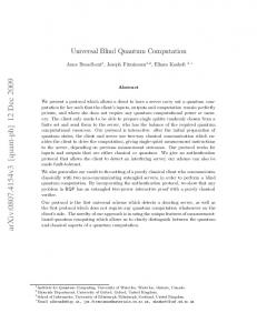
will see that the CXZ gate library is fundamentally different from the other two. Roughly, the reason is that Rx and Rz can be respectively moved past the target and control of the CNOT gate, while no such identity holds for the Ry gate. While the CXY and CYZ libraries each only contain one of {Rx , Rz }, the CXZ gate library contains both, and consequently has different characteristics. Nonetheless, gate counts will be the same in all cases. We begin with the CYZ case, which has been previously considered in [5]. Theorem VI.1 Fifteen {Ry , Rz } gates and three CNOTs suffice to simulate an arbitrary two-qubit operator. Proof: Choose α, β, δ as in Proposition V.1. Then by Proposition IV.3, one can find a, b, c, d ∈ SU(2) such that U = (a ⊗ b)C12(I ⊗ Ry (α))C21 (Rz (δ) ⊗ Ry (β))C12 (c ⊗ d) Thus, the circuit topology depicted in Figure 2 is universal. 2 Theorem VI.2 Fifteen {Rx , Ry } gates and three CNOTs suffice to simulate an arbitrary two-qubit operator.
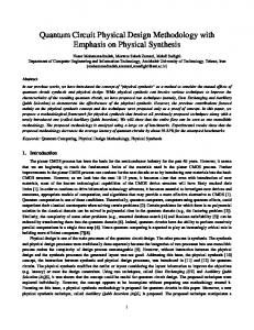
Theorem VI.3 Fifteen {Rx , Rz } gates and three CNOTs suffice to simulate an arbitrary two-qubit operator. Proof: Let U ′ be the desired operator; set U = U ′C21 . Choose θ, φ, ψ for U ′ as in Proposition V.2. By Proposition IV.3, one can find a, b, c, d ∈ SU(2) such that U(I ⊗ Rz (ψ))C21 = (a ⊗ b)C21(Rz (θ) ⊗ Rx (φ))C21 (c ⊗ d)
Rz
c
h d
h Tz† s
h Tz4 Sy† h s s
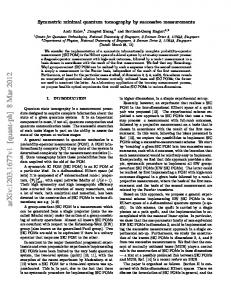
FIG. 4: The result of our algorithm applied to the two-qubit Quantum Fourier Transform. The circuit contains 3 one-qubit gates and 3 CNOTs, but the one-qubit gates are broken up into elementary gates for specificity. Here, Tz = Rz (π/4) is the T gate defined in [1] up to a global phase.
Solving for U gives the overall circuit topology in Figure 3. 2 Unlike the circuit of VI.1, the circuit in Figure 3 can be adapted to both other gate libraries. We can replace c by Sz (Sz† c) and a by (aSz )Sz† , then use the Sz , Sz† gates to change the Rx gate into an Rz . A similar trick using Rx can change the bottom Rz gates into Ry ; this yields a circuit in the CYZ gate library. As in Theorem VI.2, conjugating by H ⊗ H yields a circuit in the CXY gate library. Given an arbitrary two-qubit operator, individual gates in universal circuits can be computed by interpreting proofs of Propositions V.2, V.1, and IV.3, Theorems VI.1, VI.2 and VI.3 as algorithms. By re-ordering eigenvalues in the proof of Proposition IV.3, one may typically produce several different circuits. Similar degrees of freedom are discussed in [5]. To complete Table I, count basic gates in Figure 2 or 3.
VII.
CONCLUSIONS
n
Proof: Conjugation by H fixes SU(2 ) and Ry . It also flips CNOT gates (H ⊗2C12 H ⊗2 = C21 ) and swaps Rx with Rz . 2 Unfortunately, no such trick transforms CYZ into CXZ. Any such transformation would yield a universal two-qubit circuit topology in the CXZ library in which only three oneparameter gates occur in the middle. We show in the Appendix that no such circuit can be universal and articulate the implications of this distinction in Section VII. Nonetheless, we demonstrate here a universal two-qubit circuit topology with gates from the {Rx , Rz , CNOT} gate library that contains 15 one-qubit gates and 3 CNOT gates.
s
Tz5
b
FIG. 2: A universal two-qubit circuit with three CNOT gates. It requires 10 basic gates [3] or 18 gates from {CNOT, Ry , Rz }.
⊗n
Sy
s
Rx
h Rz
s
a
h b
FIG. 3: Another universal two-qubit circuit with three CNOT gates. It requires 10 basic gates [3] or 18 gates from {CNOT, Rx , Rz }.
Two-qubit circuit synthesis is relevant to on-going physics experiments and can be used in peephole optimization of larger circuits, where small sub-circuits are identified and simplified one at a time. This is particularly relevant to quantum communication, where protocols often transmit one qubit at a time and use encoding/decoding circuits on three qubits. We constructively synthesize small circuits for arbitrary two-qubit operators with respect to several gate libraries. Most of our lower and upper bounds on worst-case gate counts are tight, and rely on circuit identities summarized in Table II. We also prove that n-qubit circuits require ⌈ 41 (4n − 3n − 1)⌉ CNOT gates in the worst case. While our techniques do not guarantee optimal circuits for non-worst-case operators, they perform well in practice: one run of our algorithm produced the circuit shown in Figure 4 for the two-qubit Quantum Fourier Transform. We show elsewhere that this circuit has minimal basic-gate count. A somewhat surprising result of our work is the apparent asymmetry between Rx , Ry and Rz gates. While one would expect any circuit topology for CNOT, Rz and Ry to carry over to other elementary-gate libraries, we prove a negative result for the library CNOT, Rz and Rx . Namely, using Ry gates appears essential for the minimal universal circuit topology shown in Figure 2, which exhibits the maximal possible number of onequbit gates that are not between any two CNOT gates. The asymmetry between elementary one-qubit gates directly impacts peephole optimization of n-qubit circuits,
6 Circuit identities
Descriptions
CkjCkj = 1 ω j,k ω j,k = 1
CNOT-gate cancellation SWAP-gate cancellation CNOT-gate elimination
j
CkjCk = ω j,kCkj j
j
j
j
j j
j
j
Ck Rx (θ) = Rx (θ)Ck , Ck Sx = SxCk moving Rx , Sx via CNOT target j j j j Ck Rkz (θ) = Rkz (θ)Ck , Ck Szk = SzkCk moving Rz , Sz via CNOT control j
σkxCkj = Ckj σx σkx
moving σx via CNOT control
j j Ckj σz = σz σkzCkj j Ckj ω j,k = ω j,kCk V j ω j,k = ω j,kV k
moving σz via CNOT target moving CNOT via SWAP moving a 1-qubit gate via SWAP
Rn (θ)Rn (φ) = Rn (θ + φ) merging Rn gates. ~n ⊥ ~ m =⇒ Sn Rm (θ) = Rn×m (θ)Sn changing axis of rotation
sides. By Corollary III.2, there exist operators that cannot be simulated without 15 one-parameter gates; the remaining three must go in the middle of the circuit. 2 We have seen that for the CYZ and the CXY gate libraries, this lower bound is tight. We will show that this is not the case for the CXZ gate library. Before beginning the proof, we make several observations about the CXZ gate library. Note that conjugating a circuit identity by H ⊗ H exchanges Rx and Rz gates, and flips CNOTs. Two other ways to produce new identities from old are: swapping wires, and inverting the circuit – reversing the order of gates & replacing each with its inverse. For example, one may obtain one of the commutativity rules below from the other by conjugating by H ⊗ H and then swapping wires. s
TABLE II: Circuit identities used in out work. Here V j represents an arbitrary one-qubit operator acting on wire j.
where decompositions like that in Figure 2 are preferrable over that in Figure 3. For example, consider a three-qubit circuit consisting of two two-qubit blocks on lines (i) one and two, (ii) two and three. If both blocks are decomposed as in Figure 2, then the b gate from the first block and the c gate from the second block merge into one gate on line two. However, no such reduction would happen if the decomposition from Figure 3 is used. Acknowledgments and disclaimers. This work is funded by the DARPA QuIST program and an NSF grant. The views and conclusions contained herein are those of the authors and should not be interpreted as necessarily representing official policies or endorsements of employers and funding agencies.
h Rx
≡
Rx
Appendix
Proposition VII.1 Fix an elementary-gate library. There exist unitary operators U ∈ SU(4) that cannot be simulated by any two-qubit circuit in which all but two of the one-qubit gates appear either before the first or after the last CNOT gate. Proof: There are four places where the one-parameter gates can appear: at the left or right of the first or second line. If more than three gates appear in one such place, conglomerate them into a single one-qubit gate, and decompose the result into three one-parameter gates via Lemma II.1. By this method, any two-qubit circuit can be transformed into an equivalent circuit with at most 12 one-parameter gates on its
s
h
h
Rz
≡
Rz
s h
When one CNOT gate occurs immediately after another in a circuit, we say that they are adjacent. When such pairs of CNOTs share control lines, they cancel out, and otherwise may still lead to reductions as discussed below. We will be interested in circuits which do not allow such simplifications. To this end, recall that Rx gates commute past the target of a CNOT, and Rz gates commute past the control. Moreover, we have the following circuit identity: C21 (Rx (α) ⊗ Rz (β))C21 = C12 (Rz (β) ⊗ Rx (α))C12 . We say that a given collection of onequbit gates effectively separates a chain of CNOTs iff there is no way of applying the aforementioned transformation rules to force two CNOT gates to be adjacent. For example, there is no way to effectively separate two CNOTs of opposite orientation by a single Rx or Rz gate. This is illustrated below. s
We now illustrate the counterintuitive difference between (i) the CXZ library, and (ii) libraries CYZ and CXY. Namely, universal circuit topologies with certain properties exist only for the CYZ and CXY libraries. The proof of Proposition VI.1 contains a universal generic circuit with three CNOT gates and 15 Ry or Rz gates with the property that all but three of the one-qubit gates appear either before the first or after the last CNOT gate. This is minimal.
s
h
Rx
h
s
≡
s
h Rx
h s
On the other hand, two CNOT gates of the same orientation can be effectively separated by a single Rx or Rz gate, as shown below. Up to swapping wires, these are the only ways to effectively separate two CNOTs with a single Rx or Rz . h s
Rx
h
h Rz
h
s
s
s
Proposition VII.2 At least four gates from {Rx , Rz } are necessary to effectively separate four or more CNOT gates. Proof: Clearly it suffices to check this in the case of exactly four CNOTs. If three Rx , Rz gates sufficed, then one would have to go between each pair of CNOT gates. Suppose all the CNOT gates have the same orientation, say with control on the bottom wire. Then the first pair must look like one of the pairs above. In either case, we may use the identity C21 (Rx (α) ⊗ Rz (β))C21 = C12 (Rz (β) ⊗ Rx (α))C12 to flip these CNOT gates, thus ensuring that there is a consecutive pair of CNOT gates
7 with opposite orientations. As remarked above, there is no way to effectively separate these using the single one-qubit gate allotted them. 2 Denote by ωi j the SWAP gate which exchanges the ith and j-th qubits. It can be simulated using CNOTs as j j j Ci CijCi = ωi j = CijCi Cij . SWAP gates can be pushed through an elementary-gate circuit without introducing new gates. So, consider a two-qubit circuit in which adjacent CNOT gates appear. If they have the same orientation (eg. C12C12 or C21C21 ), then they cancel out and can be removed from the circuit. Otherwise, use the identity C12C21 = C21 ω12 or C21C12 = C12 ω12 and push the SWAP to the end of the circuit. We apply this technique at the level of circuit topologies and observe that since Q(T ω12 ) is measure-zero (or universal) iff Q(T ) is. By the above discussion, we can always reduce to an effectively separated circuit before checking these properties. Proposition VII.3 Almost all unitary operators U ∈ SU(4) cannot be simulated by any two-qubit circuit with CXZ gates in which all but three of the Rx , Rz gates appear either before the first or after the last CNOT. Proof: We show that any circuit topology of the form above can only simulate a measure-zero subset of SU(4); the result then follows from the fact that a countable union of measurezero sets is measure-zero. The assumption amounts to the fact that only three gates are available to effectively separate the CNOT gates. By Proposition VII.2 and the discussion immediately following it, we need only consider circuit topologies with no more than three CNOTs. On the other hand, we know from Proposition III.3 that any two-qubit circuit topology with fewer than three CNOT gates can simulate only a measure-zero subset of SU(4). Thus it suffices to consider circuit topologies with exactly three CNOT gates. Moreover, we can require that they be effectively separated, since otherwise we could reduce to a two-CNOT circuit. Three CNOTs partition a minimal two-qubit circuit in four regions. We are particularly interested in the two regions limited by CNOTs on both sides because single-qubit gates in those regions must effectively separate the CNOTs. To this end, we consider two pairs of CNOTs (the central CNOT is in both pairs), and distinguish these three cases: (1) both pairs of CNOTs consist of gates of the same orientation, (2) both consist of gates of opposite orientations, or (3) one pair has gates of the opposite orientations and the other pair has gates of the same orientation. In the second case, the CNOT gates cannot be effectively separated, since each pair of gates with opposite orientations requires two one-parameter gates to be effectively separated, and only three Rx , Rz gates are available. In the third case, two CNOTs with opposite orientations must be separated by two one-parameter gates, leaving only one Rx or Rz to separate the pair with the same orientation. Thus, the pair with the same orientation may be flipped, reducing to Case 1, as shown below.
s
Rx
h
s
h
h Rz Rx
s
≡
h s
h s
Rx
h Rz
Rx
s
Finally, consider the case in which all three CNOT gates have the same orientation. Each pair of consecutive CNOTs must have at least one Rx or Rz between them, to be effectively separated. Thus one of the pairs has a single Rx or Rz between its members, and the other has two one-qubit gates. We refer to these as the 1-pair and the 2-pair, respectively. Suppose that the one-qubit gates separating the 2-pair of CNOTs occur on different lines. If either one-qubit can commute past the CNOTs of the 2-pair, then it can move to the edge of the circuit; in this case Proposition VII.1 implies that the circuit topology we are looking at can only simulate a measure-zero subset of SU(4) (one can show that two Rx , Rz gates cannot effectively separate three CNOTs.) Otherwise, we use the identity C21 (Rx (α) ⊗ Rz (β))C21 = C12 (Rz (β) ⊗ Rx (α))C12 to flip the 2-pair, and thus 1-pair now have opposite orientations. As there is only one one-qubit gate between them, this pair is not effectively separated. For example: s h
Rx
s
s
Rx
h Rz
≡
h
s
h Rx Rz
h s
Rx
h s
We are left with the possibility that all the CNOT gates have the same orientation and that the 2-pair’s one-qubit gates appear on the same line. Both Rz , Rx must occur, or else we could combine them and apply Proposition VII.1 to show that such a circuit topology can only simulate a measure-zero subset of SU(2n). Now, if Rx Rz appears between two CNOT gates of the same orientation, then either the Rx or the Rz can commute past one of them. If the outermost gate can commute, Proposition VII.1 again implies that the circuit topology simulates only a measure-zero subset of SU(2n). Thus the inner gate can commute with the 1-pair. We have now interchanged the roles of the 1-pair and the 2-pair, thus by the previous paragraph, the gate which originally separated the 1-pair must be on the same line as the commuting gate. It follows that all gates are on the same line. Up to conjugating by H ⊗ H, swapping wires, and inverting the circuit, this leaves exactly one possibility. h
h s
Rx
s
h Rz
Rx
s
Finally, we add the four one-qubit gates on the sides, decompose each into Rx Rz Rx via Lemma II.1, and observe that an Rx gate can commute across the top and be absorbed on the other side. This leaves 14 one-parameter gates, and by Lemma II.2, such a circuit topology simulates only a measure-zero subset of SU(4). 2
8
[1] M. Nielsen and I. Chuang, Quantum Computation and Quantum Information, Cambridge Univ. Press, 2000. [2] D. P. DiVincenzo, “Two-bit gates are universal for quantum computation,” PRA 51, pp. 1015-1022, 1995, cond-mat/94. [3] A. Barenco et al., “Elementary Gates For Quantum Computation,” PRA 52, 3457-3467, 1995, quant-ph/9503016. [4] J. Zhang et al., “Exact two-qubit universal quantum circuit,” PRL 91, 027903, 2003, quant-ph/0212109. [5] S. S. Bullock and I. L. Markov, “An Elementary Two-Qubit Quantum Computation In Twenty-Three Elementary Gates,” PRA 68, 012318-012325, 2003, quant-ph/0211002. [6] F. Vatan and C. Williams, “Optimal Realization of an Arbitrary Two-Qubit Quantum Gate”, quant-ph/0308006. [7] G.Vidal and C. M. Dawson, “A Universal Quantum Circuit For Two-qubit Transformations With Three CNOT gates,” quant-ph/0307177. [8] “Optimal quantum circuit synthesis from Controlled-U gates”, J. Zhang et al., quant-ph/0308167. [9] Yu. Makhlin, “Nonlocal Properties of Two-qubit Gates and Mixed States and Optimization of Quantum Computations,” Quant. Info. Proc. 1, 243-252, 2002, quant-ph/0002045. [10] C. Bennett et al., “Mixed State Entanglement and Quantum Error Correction,” PRA 54,3824,1996,quant-ph/9604024. [11] S. Hill, K. Wooters, “Entanglement of a Pair of Quantum Bits,”
PRL 78, 5022-5025, 1997, quant-ph/9703041. [12] N. Khaneja, R. Brockett and S. J. Glaser, “Time Optimal Control In Spin Systems,” 2001 quant-ph/0006114. [13] M. Lewenstein et al., “Characterization of Separable States and Entanglement Witnesses,” PRA 63, pp. 044304-7, 2001, quant-ph/0011050. [14] E. Rains, “Polynomial Invariants of Quantum Codes,” quant-ph/9704042. [15] M. Grassl et al., “Computing Local Invariants of Qubit Systems,” PRA 58, 1833-1839, 1998, quant-ph/9712040. [16] S. Bullock and G. Brennen, “Canonical Decompositions of n-qubit Quantum Computations and Concurrence,” 2003, quant-ph/0309104. [17] E. Knill, “Approximation by Quantum Circuits,” 1995, quant-ph/9508006. [18] D. Wineland, C. Monroe, W. Itano, D. Leibfried, B. King, and D. Meekhof, ”Experimental Issues in Coherent Quantum Manipulation of Trapped Atomic Ions,” NIST Journal of Research 103, p. 259 (1998). [19] V. Guillemin and A. Pollack, Differential Topology, PrenticeHall, Inc., Englewoods Cliffs New Jersey, 1974. [20] Artin, M., Algebra, Prentice-Hall, Inc., Englewood Cliffs New Jersey, 1991.