efficient to use GPS or anchor nodes, this pa- per proposes an Anchor-Free (AF) Mobile Geo- ...... http://www.monarch.cs.cmu.edu/cmu-ns.html. [13] L. Hu and D.
Mobile Anchor-free Localization for Wireless Sensor Networks Yurong Xu1 Yi Ouyang1 Zhengyi Le1 James Ford1,2 Fillia Makedon1,2 1 Computer Science Department Dartmouth College 2 Department of Computer Science and Engineering University of Texas at Arlington {yurong, ouyang, zyle, jford, makedon}@cs.dartmouth.edu
Abstract Localization is a fundamental problem in wireless sensor networks. In this paper, we consider how to localize individual nodes in a wireless sensor network when some subset of the network nodes can be in motion at any given time. For situations in which it is not practical or costefficient to use GPS or anchor nodes, this paper proposes an Anchor-Free (AF) Mobile Geographic Distributed Localization (MGDL) algorithm for wireless sensor networks. Taking advantage of the accelerometers that are present in standard motes, MGDL monitors a moving distance for each node, then uses a procedures to detect any movement of each node. If movement is detected, then the moved node will trigger a series of mobile localization procedures to recalculate and update the location locally, such procedures will be stopped while the node stops moving. Data collected using Tmote Invent nodes (Moteiv Inc.) and simulations show that proposed detection method can efficiently detect the movement, and that the localization is accurate and the communication is efficient in different static and mobile contexts. Localization, Mobility, Wireless Sensor Networks, Anchor-Free, Multidimensional Scaling
1. Introduction In recent years, Wireless Sensor Networks (WSNs) [3] [20] have emerged as one of the key enablers for a variety of applications such as environment monitoring, vehicle tracking and mapping, and emergency response. One important problem for such applications is how to locate a node’s position. One example scenario is that of a WSN deployed as part of the static infrastructure to detect fire as well as to locate and guide fire fighters during fire emergencies by communicating with the mobile nodes carried by them, as illustrated in Figure 1. Static nodes in environment
Fire fighters with mobile nodes
Figure 1. Static Wireless Sensor Nodes Communicate with Mobile Nodes Carried by Fire Fighters for Localization
Though many localization algorithms have been proposed for wireless ad hoc networks or wireless sensor networks [5, 6, 7, 8, 9, 11, 17, 18], they assume that the nodes inside of the networks are static. Little research has been presented on considering localization in cases where the network cannot be assumed to be static. There are several potential solutions for providing localization in WSNs while considering mobile nodes existing inside of them: (1) Let mobile nodes deploy expensive global positioning systems (GPS) to get their locations. Many applications require sensor network mobility in the environments where GPS signals may not be available. Consider the above example: since the mobile nodes which are carried by fire fighters will often be deployed inside of buildings, a GPS solution is not feasible. (2) Re-execute current static localization algorithms periodically to compute the location of the mobile nodes. If some nodes are moving fast, such static localization algorithms will need to be restarted frequently in order to approach reasonable performance. If restarting the localization algorithms is done too frequently, it will have a significant energy and communication cost for localization over the entire network. (3) Redesign localization algorithms which are particularly focused on the problem of localization of mobile nodes. There are some existing mobile localization schemes, such as MCL [13], MCB [4] and ELA [19]. They rely on an assumption explained below, that anchor nodes are available and can be used for localization. This assumption is problematic in many settings, particularly in the case where anchor nodes cannot be guaranteed to be fixed at known locations. Our work focuses on finding a solution in this category that does not require any anchor nodes in computation. We use Anchor-Based (AB) to refer to the above methods that rely on some special nodes that already know their exact physical position. The alternative to AB localization is Anchor Free
(AF) localization that use no specially designated reference nodes with known physical coordinates. Because they assume that there are some anchor nodes that are aware of their exact physical location even when moving, MCL, MCB and ELA focus on ways to use these mobile anchor node to provide localization information to nearby nodes. There are several problems that may be faced under these localization algorithms: 1. The accuracy of AB schemes is related to the number of anchor nodes, so, in order to achieve high accuracy, AB schemes usually need large sets of anchor nodes. 2. The fact that AB schemes depend heavily on anchor nodes makes them vulnerable to the loss or malfunctioning of any of these anchor nodes. 3. Current AB solutions such as MCL, MCB and ELA need all nodes, or at least all anchor nodes, to broadcast their location periodically, even when there is no node movement. This paper will talk about an AF localization called MGDL for mobile WSNs. We assume that a network, which GDML is running on, is comprised mostly of low-mobility nodes which are embedded into the environment while some other nodes are carried by some mobile objects. Based on the above assumption, MGDL generates a distance measurement for each node by combining local network connection information with hop numbers generated without the help of GPS or anchor nodes. Using the accelerometers deployed in standard motes, MGDL monitors a moving distance for each node after the whole network is started, then with a probe procedure to detect any mobilility of the node. If movement is detected, then the moved node will trigger a series of procedures to recalculate/update the location for that moved node locally. This procedure will continue while movement continues to be detected. In this paper, we make the following contributions: (i) We design a movement detection procedure for standard motes in WSNs to detect the movement of a node by using accelerometers. (ii) We propose a MGDL localization algorithm in
detail, based on (i). Simulation on the algorithm shows that the MGDL has high accuracy in localization in different placements of networks, as well as an efficient communication cost while facing different situations of mobility. The remainder of the paper is organized as follows. Section 2 talks about related work; Section 3 discusses the detail of our Mobile Geographic Distributed localization algorithm; Section 4 reports simulation results. Finally, Section 5 gives our conclusions.
2
Related Work
The majority of prior research related to localization problems has primarily focused on static sensor networks [5, 6, 7, 8, 9, 11, 17, 18]. Recently, however, more attention has been paid to mobile environments. ˇ S. Capkun et al. proposed an Anchor-Free localization called SPA for Mobile WSNs in [11], which localizes nodes in mobile sensor networks through triangulation of neighbor nodes. SPA first computes a relative coordinate system for each node, then converts the above relative coordinate systems in each node into a global coordinate system by calculating differences in terms of distance and direction between each node and a particular central node, or a dense group of nodes called Location Reference Group (LRG). The problem for SPA is that if any nodes, especially those nodes inside an LRG, are moved, then a recalculation must be done to almost the whole network, which is costly and unnecessary. In [13], Hu and Evans present a range-free Anchor-Based localization algorithm for mobile sensor networks based on the Sequential Monte Carlo method [10]. The Monte Carlo method has been extensively used in robotics [6] where a robot estimates its localization based on its motion, perception and possibly a prelearned map of its environment. Hu and Evans extend the Monte Carlo method as used in robotics to support the localization of sensors in unmapped terrain. The au-
thors assume a sensor has little control and knowledge over its movement, in contrast to a robot. A similar paper [4] shares the same idea. By using an analogy with a system of springs and masses, the Elastic Localization Algorithm (ELA) [19], as an anchor-based algorithm, tries to calculate locations with anchor nodes which already know their locations. A mobile version of ELA supports mobile localization by updating neighbors’ locations in each node at fixed intervals. Such periodic updating in the whole network may lead to huge communication and computation costs. Work in [14] proposes an anchor-free method which focuses on locating group movement— cases in which multiple nodes have a similar direction and velocity. By deploying a compass in each node to detect the direction of a node, each node computes the relative locations of its neighbors. The work in [14] pays particular attention to group movement, and does not consider independent movements by individual nodes, which is an important and common case in mobile networks.
3
Mobile Geographic Distributed Localization (MGDL)
In this section, we will introduce the Mobile Geographic Distributed Localization (MGDL) algorithm in detail. 3.1
Overview of MGDL Algorithm
We assume that a node in a WSN can be either in a mobile or a static state, and in order to distinguish the state of a node, we use “mobile” or “static” to distinguish whether a node is mobile or not. At the same time, we use “updated” or “non-updated” to distinguish whether a node is localized or not. Combining these labels gives four states, which are represented as S/N (“Static/Non-updated”), S/U (“Static/Updated”), M/N (“Mobile/NonUpdated”) and M/U (“Mobile/Updated”).
Based on the assumption that each node in the networks stays in the “S/N” state initially, MGDL uses a technique similar to hop-counting as a measurement procedure (Section 3.2) to measure the distance from some bootstrap node to other nodes. After the running of the measurement procedure, each node will collect a set of hop coordinates from its neighbor nodes that are within one (or k) hop(s) distance of itself, and then it will run Dijkstra’s algorithm to get the shortest path between each pair of nodes. After that, it will construct a local map (Section 3.3) using MDS (Multidimensional Scaling). A transformation procedure (Section 3.4) will merge the local map inside of each node into a global map. After all the above procedures are done, the state of the node will be set as “S/U”. In order to detect the movement of a node, we utilize an accelerometer, which is a standard component in many current motes (such as Moteiv’s Invent [2]), to detect the movement of the node. If there is a node that is starting to move inside of the network, the accelerometer can detect its acceleration, and then our algorithm will compute the total distance moved based on the acceleration. If this distance is beyond a threshold, then the state of the node will be set as “M/N”, and mobile localization procedures (Sections 3.3, 3.6, 3.7) will be triggered to resample hop-coordinates again, to recompute the local map and transformation matrix for that local map in order to merge this map into the global map. While movement continues to be detected, the above procedures will continue. Once movement is no longer detected, the above updating procedures will be stopped and the state of the node will be set back to “S/U”. Figure 2 shows the states and the whole MGDL algorithm for a node. 3.2
Measurement Procedure
In the measurement step, we assume that all nodes inside of the networks are static at this step (which is reasonable, since a measurement proce-
Static/Non-updated State Measurement Procedure Local Map Computation Procedure Transformation Procedure Static/Updated State Detect Movement? Y
N
Mobile/Non-Updated State Resampling Procedure Local Map Computation Procedure Retransformation Procedure Mobile/Updated State
Figure 2. Sensor States and MGDL Algorithm
dure is relatively fast, and need only be run once at the time of the network deployment). We use the hop-coordinates [21] technique, which is similar to hop-counting but has more accurate measurement, to flood a message to the network to finish the measurement. The basic idea is: (i) In bootstrap node: A bootstrap node (x) creates a measurement message with (i = x) to flood the network. After that, the bootstrap node will drop any measurement message originated by itself. (ii) In all other nodes in the WSN: Suppose that an arbitrary node a is calculating its hop distance, and node b is one of the neighbors of node a. Then the basic hop-coordinates procedure for node a is shown in Procedure 1. Here, a is a node, hopa is the minimum number of hops to reach node a counting from some bootstrap node (x), the combination of hopa and offseta is the hop coordinate for node a, Na is a set of nodes which can be reached by node a in one hop, and |Na | is the number of nodes in Na . The total cost for this step is as follows: a computational cost of O(1), a communication cost of
Procedure 1 Measurement Procedure in node a 1: INPUT: message (hopb ) from node b ∈ Na 2: for message (hopb ) from any B ∈ Na and not TIMEOUT do 3: if hopb < hopa then 4: hopa = hopb + 1 5: forward( message(hopa )) to MAC 6: else 7: drop( message(hopb ) ) 8: end if 9: end for 10: if |Na | == 0 then 11: offseta = 0 12: else P (hop −(hopa −1))+1 13: offseta = b∈Na 2(|Nb a |+1) 14: end if 15: return hop-coordinate hopa + offseta O(Na ), a memory cost of O(Na ) for each node, and a communication cost of O(n) for the whole network. 3.3
Local Map Computation
In this step, each node will compute a local map for it’s neighbors based on the hop-coordinate computed in the previous step. After the generation of hop-coordinates with Procedure 1, each node will send a request to its neighbor nodes that are within one (k) hop(s) to send back their hop coordinate from some bootstrap node (x). After each node receives the hop coordinate from its neighbors, that node will compute shortest paths between all pairs of nodes one (k) hop(s) to that node, using Dijkstra’s algorithm or other similar algorithms. Then, we apply MDS to the (|N a |+1)×(|N a |+1) shortest path matrix (here |N a | is the number of nodes that can be reached by node A in one(k) hop(s)) and retain the first two (or three) largest eigenvalues and eigenvectors to construct a 2-D (or 3-D) local map. The total cost for this step is a computational cost of O(|Na |3 n) and a memory cost of O(|Na |2 )
per node, with no communication cost in this step. 3.4
Transformation Procedure
In this step, we will continue the localization process in order to assemble the local maps that are computed and stored in each node into a global map through a transformation. First, we will bootstrap from some node to compute the transformation matrix for that node and follow it by broadcasting a transformation message to its neighbors to let them start to compute the transformation matrix with their neighbors, too. Then, after we find the set of neighboring nodes, we compute a transformation matrix for each node b in the neighbor node set Na of node a. Suppose that there are two sets of neighbor nodes, Na and Nb , that are within one (or k) hop(s) of the nodes a and b, respectively. Their intersection isI = Na ∩ Nb , and we use matrix Ia = n o0 0 . . . , (xi , yi ) , . . . (here (xi , yi ) are the coordinates of one node i) to represent the coordinates of nodes in the I generated by node a, and simin
0
o0
larly Ib = . . . , (x`i , y`i ) , . . . for node b. We can then computeqa transformation matrix T such that P ((xi − xˇi )2 + (yi − yˇi )2 ), where it minimizes (xi , yi ) ∈ Ia , (x`i , y`i ) ∈ Ib , and (xˇi , yˇi ) ∈ Ib × T . The procedure is given in Procedure 2. If a node receives a transformation matrix T, then it will first check whether it is already transformed or not; if so, the node will drop such a message, and if not, it will apply Procedure 2. This will allow the node to compute the local map (which will be a part of the global map) which it will then send to its |Na | neighbor nodes. At the same time, the node will find its neighbor node set, and will compute transformation matrix T for each node in the set using Procedure 2. After we have flooded the network to the transformation step in the whole networks, we archive the global map for the whole network, which is
Procedure 2 Compute transformation matrix T in node a Require: Input: matrix T from neighbor node 1: if this node is transformed then 2: drop(matrix T) 3: return 4: end if 5: for each node b ∈ Na do 6: request Nb from node b T 7: I = Nb Na 8: generate Ib and Ia from I 9: compute transformation matrix T such that q P ((xi − xˇi )2 + (yi − yˇi )2 )is minimized, here (xi , yi ) ∈ Ia ,(xˇi , yˇi ) ∈ Ib × T . 10: send matrix T to node b 11: end for 12: set (this node is transformed) stored in a distributed way in each node in the network. Total cost for this step: computational cost of O(|N a |), memory cost of O(|N a |) for nodes, and communication cost of O(1) for each node or O(n) for whole network. 3.5
Mobile Measurement Techniques
Until now, we have only talked about how to do localization without considering mobility of nodes (after the previous procedures, current state of a node is S/U). In this section, we will solve the problem of how to decide whether a node has moved, then how to recompute the location of mobile nodes. 3.5.1
2D and 3D Accelerometer
In order to detect the movement of mobile nodes, we need some sensor which can detect and quantify node movement. In our algorithm, we make use of accelerometers installed in standard nodes to detect their movement. An accelerometer is a device that measures its own acceleration. We can use a 2D (X-Y) accelerometer to measure 2D
acceleration,or a 3D (X-Y-Z) version to measure 3D acceleration. The component we used for 2D in this paper is a standard component in current commercial motes, such as the Moteiv Inventor mote [2]. In order to detect 3D movement of the node, one can install an inexpensive external 3D accelerometer, such as the MMA7260Q accelerometer [1] from Freescale. 3.5.2
Movement Detection
With the aid of a 2D accelerometer, we can roughly measure the acceleration vector ~a in a plane. Since the accelerometer can’t detect the rotation of a node, it is of limited use as a direct way to measure position changes. Therefore, we use the integral of the absolute value of the ~a to computeR an approximation of the moved disR tance d = |~a|d2 t. If such distance is beyond a threshold, we then say this node has moved. First we assume that at the beginning of time t = 0, every node inside of the network is still. Consider an arbitrary node: suppose its acceleration ~a = 0, its velocity v = 0, the distance it has moved d = 0 for that node. Then, we will sample the accelerometer in that node periodically. Here, we assume that the interval time for sampling is dt, and the reading of acceleration from the accelerometer in that node is shown as ~a, so current velocity for this node can be approximated R as v = |~a|dt, and the distance moved from the beginning location (when t = 0), can be approxRR imated as d = |~a|d2 t. If d is beyond a threshold �, we then say this node has moved, and we let v = 0 and d = 0 to restart the measurement. Thus, though the values of ~a, v and d are not accurate, in comparison to their real values, they are sufficient to detect the movement of a node. The complete process is described in Procedure 3. If Procedure 3 detects that a node has moved, then MGDL in that node will recompute its location. Threshold � will decide when a mobile node should recompute its location. The smaller the threshold is, the higher the frequency with which
10
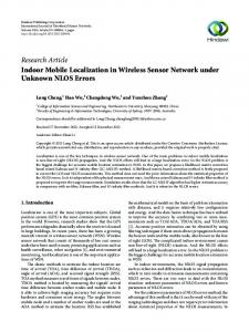
|acce| (m/s2) Actual Movement Distance (m) Detect Movement
9 8
Value
7 6 5 4 3 2 1
44
43
42
41
40
39
38
37
36
35
34
33
32
31
30
29
28
27
26
25
24
23
22
21
20
19
18
17
16
15
14
13
12
11
9
10
8
7
6
5
4
3
2
1
0
0 Time(s)
Figure 3. First 40 Seconds of Experiment on Movement Detection with Accelerometer. Movement is detected within each movement block, although with a slight lag, and is only occasionally spuriously detected between movements. (Here dt = 0.1s, threshold � = 1.5m. If a node is moving then actual
movement will be shown as value =5, otherwise actual movement will be shown as value =0.)
the node computes its location, leading to higher localization accuracy as well as more communication cost. Procedure 3 Movement Detection Procedure Require: this procedure will be invoked to read the accelerometer Rduring the time period dt. 1: v = previous v + |~ a|dt R 2: d = previous d + vdt 3: if d > threshold � then 4: v=0 5: d=0 6: return “detect movement” 7: end if 8: return “un-detect movement” In order to evaluate how to detect the movement of a node with the above procedure, we set up an experimental environment in a long hallway (about 50 m). A node carried by one person works as a mobile node. The above movement detection procedure is running inside of that node with dt = 0.1s. At first, we will let the mobile node start to move from one end of the hall, and move for 5 seconds with walking speed, then stop for 5 seconds in the same hall, and so on until reaching the end of the hall, then turn back with the same movement. The first 40 seconds of this
experiment is shown in Figure 3. From Figure 3, we can see that this movement detection procedure can detect the movement of a node when that node is moving, albeit with an average delay of about 0.95 s. 3.6
Resampling Procedure
If we detect that a node is moving with the movement detection procedure above (Procedure ), we will mark this node as “M/N” (mobile but Non-updated). Then, we will resample the hop-coordinate for this node from its neighbors. In order to increase the accuracy of resampling, we only get hop-coordinates from nodes that are marked as static or S/U, instead of from nodes marked as mobile (“M/N” or “M/U”). The whole procedure is described in Procedure 3. The total cost for this step is as follows: computational cost of O(1), communication cost of O(Na ), memory cost of O(Na ) for each node, and O(n) for the whole network. 3.7
ReTransformation Procedure
After the resampling procedure and local map computation, we transform the local map in this moved node into the global map. In this process
Procedure 4 Resampling Procedure for Node a 1: if |Na | == 0 then 2: keep the previous offseta and hopa 3: else 4: for each node b ∈ Na , for which the state of node b is “S/U” do 5: request hopb from node b 6: end for P (hopb +hopb +of f seta ) 7: offseta + hopa = b∈Na |Na | 8: end if 9: return hopa + offseta
Total cost for this step: computational cost of O(|N a |), memory cost of O(|N a |) for nodes, and communication cost of O(1) for each node or O(n) for whole network.
4
Simulation Result
In this section, we will talk simulation results for our algorithm. 4.1
Simulation Configuration 120
we get a new transformation matrix for this local map, since the old transformation matrix is new out of date. Suppose this moved node is node a; first, we find a closest neighbor neighbor node with S/U state (here we assume it is node b); then compute a new transformation matrix T for node a. Suppose that there are two sets of neighbor nodes Na and Nb for nodes a, b, respectively. Their intersection is I = Na ∩Nb , and we use man o0 0 trix Ia = . . . , (xi , yi ) , . . . (here (xi , yi ) are the coordinates of one node i) to represent the coordinates of nodes in the I generated by node a, and n
0
o0
similarly Ib = . . . , (x`i , y`i ) , . . . for node b. We can then compute a q transformation matrix T such P ((xi − xˇi )2 + (yi − yˇi )2 ), that it minimizes where (xi , yi ) ∈ Ia , (x`i , y`i ) ∈ Ib , and (xˇi , yˇi ) ∈ Ib × T . The procedure is given in Procedure 5. Procedure 5 Recalculate Transformation Matrix T for Node a 1: find node b from Na , such that |hopa + offseta − (hopb + offsetb )| is minimized. 2: request Nb from node b 3: request Tb from node b T 4: I = Nb Na 5: generate Ib and Ia from I 6: compute transformation matrix T such that qP ((xi − xˇi )2 + (yi − yˇi )2 )is minimized, here (xi , yi ) ∈ Ia × Ta , (xˇi , yˇi ) ∈ Ib × Tb . 7: set this node to M/U state.
100
80
60
40
20
0
0
20
40
60
80
100
120
Figure 4. A typical placement for simulation,
constructed with n = 400, r = 4. Green dashed ovals are holes and small blue circles are islands. We implemented our localization algorithm as a routing agent and our bootstrap node program as a protocol agent in NS-2 version 2.29 [16] with 802.15.4 MAC layer [22] and CMU wireless [12] extensions. The configuration used for NS-2 is RF range = 15 meters, propagation = TwoRayGround, antenna = OmniAntenna. In our experiments, we used uniform placement—n nodes are placed on a grid with ±0.5r randomized placement error. Here r is the width of a small square in the grid. We constructed a total of 60 placements with n = 36, 100, 250, 400, 625, 900, 1600, 2250, and 2500, and with r = 2, 4, 6, 8, 10 and 12 meters, respectively. The reason we use uniform
120
300
100
80
MGDL (Mobile Nodes) MGDL (Static Nodes) MCL ELA
60
40
20
Average Error (%R)
Average Error (%R)
250
MGDL (Mobile Nodes) MGDL (Static Nodes) MCL
200
150
100
50
0
0
36
100
225
400
625
900
1225
1600
2025
2500
36
# of nodes
Figure MGDL,
100
225
400
625
900
1225
# of nodes
1600
2025
2500
5. Accuracy Comparison with MCL and ELA. Here, ND=10,
Figure 6. Overall Accuracy Comparison with MGDL and MCL. Here, ND =4.6,
and Vavg = 1R/s, Number of Anchors = 4, Number of Nodes = 36,100,225,400, 625,900,1225,1600,2025,2500, threshold � = 0.1R.
6.5,10,17.5,38,144, Vavg = 1R/s, Number of Anchors = 4, Number of Nodes = 36,100, 225,400,625,900,1225,1600,2025,2500, threshold � = 0.1R
placement with ±0.5r error is that usually such a placement produces both node holes and islands in one placement, as demonstrated in Figure 4. To better simulate realistic mobile network situations, in each placement, we let most of the nodes inside of the network work as static nodes deployed in the environment, while about 10% of the nodes move inside the network under the following mobility model.
begins the simulation by remaining stationary. It then selects a random destination in the network space and moves to that destination at a speed randomized from a uniform distribution between 0 and some maximum speed. Upon reaching the destination, the node selects another destination, again, and proceeds there as previously described, repeating this behavior for the duration of the simulation. Each simulation ran for 120 seconds of simulated time.
4.1.1
Mobility Model
Mobile nodes in the simulation move according to a model that is called as the “random waypoint” model [15]. It is one of the most commonly used mobility models for mobile ad hoc networks. In the random waypoint model, a node randomly chooses its destination, its speed of movement, and its pause time after arriving at the destination. In our simulation we use a pause time of zero. It is hard to simulate an accelerometer in NS-2, so for simplification, we feed the moved distance of one node to the motion deteciton procedure in that node. Each node controlled by the mobility model,
4.1.2
Simulation Parameters
We will control the following parameters in our simulations: 1. Average speed of nodes (Vavg ): We represent the speed as the moving distance per time unit. A node‘s speed is chosen from a uniform distribution [0, 2 ∗ Vavg ], so that the average velocity equals Vavg . 2. Node Density (ND): The average number of nodes in one hop transmission range. In our placements, we chose r = 2, 4, 6, 8, 10 and 12 meters, which corresponds to ND = 144, 38, 17.5, 10, 6.5, and 4.6, respectively.
100
300
MGDL (Mobile Nodes) MGDL (Static Nodes) MCL ELA
200
150
MGDL (Mobile Nodes) MGDL (Static Nodes)
100
Average Error (%R)
Average Error (%R)
250
90 80 70 60 50 40 30
MCL
20
50
10 0
0
4.6
6.5
7.8
10 13.7 16.5 17.5 Network Density (ND)
19.4
38
4.6
144
6.5
10 17.5 Network Density (ND)
38
144
Figure 7. Comparison of Accuracy Vs. Density of the Networks with MCL. Here,
Figure 8. Comparison of Accuracy Vs. Density of the networks with MCL. Here, number
ND =4.6,6.5,10,17.5,38,144, Vavg = 1R/s, Number of Anchors = 4, number of Nodes = 36,100,225,400,625,900,1225,1600,2025,2500, Threshold � = 0.1R
of nodes is 400 (40 anchor nodes inside them for ELA and MCL), Vavg =1R/s, threshold � = 0.1R.
3. Number of nodes: The total number of nodes inside a WSN. 4. Threshold (�): A threshold is used to judge whether the current node is moving or not. We assume a fixed threshold � = 0.1R for all simulations (except in varying of � in Section 4.6). 4.2
Localization Accuracy
The key metric for evaluating a mobile localization technique is the accuracy of location when nodes are moving. Since MGDL is an AF localization, it does not use anchor nodes, while such anchor nodes will be needed inside of the MCL and ELA. In order to compare MGDL with MCL, and other localization algorithms, we assume that there are only 4 anchor nodes in both MCL and MGDL, in all placements, except as noted. Because at the same time there are some nodes moving and some nodes being still, we also compute the accuracy of localization for mobile nodes and still nodes, separately. First we compare these three algorithms under different number of nodes. ELA only has data when ND = 10 available. Figure 5 shows the
comparison of localization accuracy of MGDL vs. MCL, ELA under different number of nodes = 36, 100, 225, 400, 625, 900, 1225, 1600, 2025, 2500, when ND = 10. Figure 6 compares the localization accuracy of MGDL vs. MCL under different number of nodes with different ND = 144, 38, 17.5, 10, 6.5, 4.6. Both figures share same additional parameters as Vavg = 1R/s, and threshold � = 0.1R for MGDL. From the figures we can see that MGDL, unlike MCL or ELA, has stable performance on localization accuracy even when the number of nodes is very large, while MCL and ELA usually only have good performance when the number of nodes is small. To achieve good performance with more nodes, it is necessary that they should increase the number of anchor nodes significantly. 4.3
Node Density
Since ELA only has data with number of nodes = 400 available for node density, Figure 8 shows the comparison of localization accuracy of MGDL, MCL and ELA under number of nodes = 400. Even when there are about 10% anchor nodes inside of the network for ELA and MCL,
80
100
MGDL (Mobile Nodes) (V=1R/S) MGDL (Mobile Nodes) (V=0.5R/S) MGDL (Mobile Nodes) (V=0.1R/S) MGDL (Mobile Nodes) (V=0.01R/S) MCL (V=1,0.5,0.1,0 R/S)
MGDL (Static Nodes)
60
MCL
Communication Overhead
Average Error (%R)
MGDL (Mobile Nodes) 70
50 40 30 20
10
1
0.1
10 0
0.01
0
0.2
0.4
0.6
0.8
1
1.2
1.4
1.6
1.8
2
Speed of Nodes (Vavg ) (R/s)
0.1
0.2
0.3
0.4
0.5 0.6 Threshold (R)
0.7
0.8
0.9
1
Figure 9. Impact of Node Speed Vavg on MGDL and MCL. Here, # of anchor nodes for MCL is about 10% of number of total nodes.
Figure 10. Communication Overhead with Different Threshold Value on MGDL and MCL under Different Vavg . Here communication
Overhead is measured by the average # of messages per node per second. MGDL can still achieve an improvement of about 20% of R on average in localization accuracy over MCL, and an improvement of about 28%R over ELA. Here we again note that the results from MCL and ELA are based on using about 10% nodes as anchor nodes, while our algorithm does’t depend on anchor nodes when computing the global map for the networks. Figure 7 shows the impact of node density over all 60 placements on MGDL and MCL. MGDL is far beyond MCL in different node densities. 4.4
Node Speed
Figure 9 compares the localization accuracy of MGDL vs. MCL under the varying of Vavg from 0 to 1R. Even when the number of anchor nodes for MCL is about 10% of the number of total nodes, we can see that MGDL shows low localization error when nodes are in low-mobility, while MCL is encoutering higher error. MGDL achieves an average of 22%R more location accuracy for the overall varying of Vavg from 0 to 1R. 4.5
Communication Overhead
One important consideration for WSNs is lowering communications overhead. Here, we measure communication overhead with the average
number of messages transmitted by a node each second. From Figure 10, we can see that the lower the speed of mobile nodes is inside of the network, the lower the communication overhead is in MGDL, while MCL keep the same communication overhead. This phenomenon shows that our algorithm can efficiently adjust the communication overhead to save more energy when localizing low-speed mobile nodes while keep reasonable accuracy for high-speed mobile nodes, as shown in Figure 9. Also, at a given communication speed, we can decrease communication overhead by increasing the threshold �, at the cost of a slower update frequency for mobile localization. 4.6
Localization Coverage
In comparison with MCL, another advantage of MGDL is that MGDL has higher percentage of nodes that could be localized under same node density. The percentage of localized nodes of MCL is 92.13% on average, with results at particular values of R ranging from 96.87% (2Vavg = 0.45R) to 86.44% (2Vavg = 1R) down to 44.81% (2Vavg = 2R). This comes from the fact that MCL is not able to draw enough good samples from
an area in which there is overlap of the anchors’ radio range. This occurs in general with high maximum node speeds. In the worst case, the new sample set remains empty leading to a nonlocalized node. The average coverage for MGDL is quite invariant to the speed of the node, but much related to the number of neighbors a node has. Even in our worst simulation cases, the percentage of nodes that could be localizedis is more than 97.3%, with the average precentage is 99.4% for the whole data set in simuation.
5. Summary In this paper, we proposed an anchor-free localization for Mobile WSNs. By making use of a standard device accelerometer, we proposed a set of movement detection algorithms, and by testing them on Moteiv’s Invent motes, we verify that our approach is reasonable. Then based on such movement detection, we provided the whole AF localization algorithm called Mobile Geographic Distributed Localization (MGDL). Based on simulation in NS-2, we found that our algorithm has more accurate localization results than previous mobile localization algorithms. Also, MGDL obtains better coverage than AB mobile localization algorithms that we compared to (MCL). MGDL has flexible communication overhead for both high-mobility and low-mobility nodes, while MCL only has fixed communication overhead for both high-mobility and low-mobility nodes, which may impose overly high communication overhead in the latter case.
References [1] Freescale Inc., MMA7260Q 3D Accelerometer. URL http://www.freescale.com/. [2] Moteiv Inc., Invent Motes. URL http://www.moteiv.com. [3] I. Akyildiz, W. Su, Y. Sankarasubramaniam, and E. Cayirci. A survey on sensor networks. Communications Magazine, IEEE, 40(8):102–114, 2002.
[4] K. L. Aline Baggio. Monte-carlo localization for mobile wireless sensor networks. In 2nd Int. Conference on Mobile Ad-hoc and Sensor Networks (MSN 2006), Hong Kong, China, December, 2006. [5] J. Ash and L. Potter. Sensor network localization via received signal strength measurements with directional antennas. Proceedings of the 2004 Allerton Conference on Communication, Control, and Computing, 2004. [6] P. Bahl and V. Padmanabhan. RADAR: an inbuilding RF-based user location and tracking system. INFOCOM 2000. Nineteenth Annual Joint Conference of the IEEE Computer and Communications Societies. Proceedings. IEEE, 2000. [7] R. Bischoff and R. Wattenhofer. Analyzing connectivity-based multi-hop ad-hoc positioning. Pervasive Computing and Communications, 2004. PerCom 2004. Proceedings of the Second IEEE Annual Conference on, pages 165–174, 2004. [8] J. Bruck, J. Gao, and A. Jiang. Localization and routing in sensor networks by local angle information. Proceedings of the 6th ACM international symposium on Mobile ad hoc networking and computing, pages 181–192, 2005. [9] N. Bulusu, J. Heidemann, and D. Estrin. GPSless low-cost outdoor localization for very small devices. Personal Communications, IEEE [see also IEEE Wireless Communications], 7(5):28– 34, 2000. [10] W. Burgard, D. Fox, D. Hennig, and T. Schmidt. Estimating the absolute position of a mobile robot using position probability grids. Proceedings of the Thirteenth National Conference on Artificial Intelligence, pages 896–901, 1996. ˇ [11] S. Capkun, M. Hamdi, and J. Hubaux. GPS-free Positioning in Mobile Ad Hoc Networks. Cluster Computing, 5(2):157–167, 2002. [12] T. C. M. Group. Wireless and Mobility Extensions to ns-2. obtain from http://www.monarch.cs.cmu.edu/cmu-ns.html. [13] L. Hu and D. Evans. Localization for mobile sensor networks. Proceedings of the 10th annual international conference on Mobile computing and networking, pages 45–57, 2004.
[14] H. B. A. D. H¨useyin Akcan, Vassil Kriakov. Gpsfree node localization in mobile wireless sensor networks. Proceedings of the 5th ACM international workshop on Data engineering for wireless and mobile access (MobiDE 2006), 2006. [15] D. Johnson and D. Maltz. Dynamic source routing in ad hoc wireless networks. Mobile Computing, 353:153–181, 1996. [16] S. McCanne and S. Floyd. ns-2 Network Simulator. Obtain via: http://www. isi. edu/nsnam/ns. [17] Y. Shang and W. Ruml. Improved MDS-based localization. INFOCOM 2004. Twenty-third AnnualJoint Conference of the IEEE Computer and Communications Societies, 4, 2004. [18] Y. Shang, W. Ruml, Y. Zhang, and M. Fromherz. Localization from mere connectivity. Proceedings of the 4th ACM international symposium on Mobile ad hoc networking & computing, pages 201–212, 2003. [19] P. Vicaire and J. Stankovic. Elastic Localization: Improvements on Distributed, Range Free Localization for Wireless Sensor Networks. Technical report, Tech. Rep. CS-2004-35, University of Virginia, 2004. [20] M. Vieira, C. Coelho Jr, D. da Silva Jr, and J. da Mata. Survey on wireless sensor network devices. IEEE Emerging Technologies and Factory Automation, pages 537–544, 2003. [21] Y. Xu, J. Ford, and F. S. Makedon. A Variation on Hop-counting for Geographic Routing. Embedded Networked Sensors, 2006. EmNetSIII. The third IEEE Workshop on, 2006. [22] J. Zheng and et.al. 802.15.4 extension to NS-2. Obtain via: http://wwwee.ccny.cuny.edu/zheng/pub.