Mobile Robot Self-Localization System using IRUWB Sensor in Indoor Environments Marcelo J. Segura, Vicente A. Mut, Hector D. Patiño Institute of Automatics National University of San Juan, San Juan, Argentina. e-mail: {msegura; vmut;
[email protected]} Abstract— Robot localization is a fundamental problem in mobile robotics. This paper proposes the use of a new type of sensor that permits accurate localization in indoor environments. An Impulse Radio (IR) Ultra Wide-Band (UWB) sensor uses very short baseband pulses for transmission. This sensor facilitates the development of indoor location and tracking applications based on time of arrival estimation with great accuracy. There are many different sensors and techniques that have been proposed for indoor localization; however they usually have large errors in Non Line of Sight (NLOS) conditions or with certain environment conditions. The objective of this paper is to propose a self-localization system based on Time of Arrival (TOA) estimation algorithm that permits precise localization in indoor environments with obstructed line of sight. This work proposes a new wavelet cyclic cross correlation strategy for time of arrival estimation based on non-coherent receiver structure and sliding correlation techniques for multiple user differentiation. The simulation results show that the propose localization system overcome the problems of NLOS conditions and makes possible the mobile robot localization with small number of base stations. Keywords: indoor localization, mobile robot, time of arrival, ultra wideband.
I.
INTRODUCTION
Robot localization and tracking in indoor environments has been recognized as a fundamental problem in mobile robots. There are different applications like industrial mobile robots, stock control and logistics in warehouses, mobility assistance for handicapped people or patient monitoring in hospitals that require accurate position estimation. Current robot sensors are based on ultrasound, laser scanner or stereo vision but these types of sensors have different limits in harsh indoor environments, like multipath and light conditions. There are different techniques that estimate the position using Radio Frequency (RF) measurements. The most used are based on Angle of Arrival (AOA), Received Signal Strength (RSS) and Time of Arrival (TOA) [1]. The TOA method was selected because it can be shown that it achieves the best accuracy related with Cramér-Rao lower bound (CRLB) [2]. The achievable accuracy is highly dependent on clock synchronization between the nodes, so a Time Difference of Arrival (TDOA) technique is implemented in order to avoid this problem.
978-1-4244-4778-7/09/$25.00 ©2009 IEEE
There are different wireless technologies, like WiFi and ZigBee that have been proposed for indoor localization. Generally, theses localization systems are based on low cost and low power sensors that measure the RSS. The main problem of RSS estimation is that position errors are nearly 1 meter, which is unacceptable for robot localization. For this reason, an Impulse Radio Ultra Wide-Band (IR-UWB) sensor that measures the signal TOA was proposed. With the aim of designing a low cost sensor, digital implementation of UWB sensor on FPGA (Field Programmable Gate Array) was selected. The typical approach for indoor localization consists of multiple base stations (BS) that receive an UWB signal from a source to be localized. The received signals are processed in a central control unit that estimated the mobile robot (MR) position [3]. One weakness of this remote location system is that position information must be feedback to the mobile vehicle, sometimes using a different communication system [4]. The processing and feedback time, constrain the sample time in the navigation control system because the robot must wait for position information before moving. On the other hand, when the number of MR increases the receiver algorithm is more complex and requires more processing time. This work suggests a self-localization algorithm that consists of synchronized reference nodes or BS, that transmit a coded repeated stream of ultrashort pulses p(t). Therefore, this localization algorithm works in the opposite way of remote localization. The proposed algorithm runs on the MR, which receive the signals from base stations and estimated its position based on TOA measurements. With this proposal the transmitter and receiver algorithms are not modified when the number of MR increase. The main contribution of this work is related to the design of a TOA estimation algorithm that permits mobile robot self localization in indoor environment with obstructed Line of Sight (LOS). Since localization accuracy depends on TOA estimation performance, this paper is focused on the evaluation of proposed receiver structure and TOA estimation algorithm. Also, the final position estimation and the RMS errors were evaluated. This paper is structured as follows. Section II describes the channel and signal model and the principal characteristics of IR-UWB system. Section III describes the UWB sensor
architecture. Section IV explains the proposed TOA estimation method. Section V describes the position estimation algorithm. Section VI shows the simulation analysis and results. Finally, section VII gives the conclusions. II.
UWB COMMUNICATION SYSTEM MODEL
In UWB communication there are different bands that can be used depending on the application. The frequency band below 960 MHz was selected because was demonstrated that this frequency range has excellent performance for indoor and industrial environments [5]. The pulse shape must satisfy the regulation; hence a Scholtz pulse was selected, which is the second derivate of Gaussian pulse [6]. An IR-UWB system transmits each information symbol over a time interval of Ts second, that consists of Nf frames of length Tf and the resultant symbol length is Ts=NfTf. In each frame a short pulse p(t) of Tp=2 nanosecond is transmitted with the selected shape. Pulse Amplitude Modulation (PAM) is used for simplifying the transmitter architecture. The k symbols of the base station u (BSu), are defined as su(k) with energy εu. The mobile robot must identify multiple signals that come from different base stations. In order to differentiate the TOA of each BS, the use of Direct Sequence (DS) Gold spreading code of length Nf is proposed. On the other hand, if the base stations transmit at the same time, inter pulse interference (IPI) takes place, hence a simple time division multiple access (TDMA) was implemented. Each BS transmits the assigned DS code during its slot index uslot of length Tf. The final DS-UWB TDMA transmitted signal is xu(t):
⎛⎢ k εu xu (t ) = su ⎜ ⎢ ∑ N f k =0 ⎜⎝ ⎣⎢ N f ∞
(
)
⎥⎞ ⎥ ⎟⎟ cu (k ) p(t − kTTDMA − uslotTf ) ⎦⎥ ⎠
(1)
where su ⎣k / N f ⎦ is the modulated symbol during the k frame, cu(k) Є{-1,+1} is the spreading code for BSu that modified the pulse amplitude frame to frame, uslot={0, 1,…,NBS-1}, TTDMA=Tf.NBS is the TDMA frame and NBS is the number of base stations, in our case NBS=4. In order to avoid inter frame interference (IFI), Tf=350ns was selected because it is the worst channel delay spread case. In this work, the channel model proposed by Cassioli [7] was implemented. Cassioli model is a stochastic taped delay line model, in which the environment is considered dense, so multipath signals arrive all together in the same cluster. It is important to mention that this model is considered as NLOS, because the measurements were done in an indoor office with obstructed LOS. In our case the channel impulse response is: K
hu (t ) = ∑ α k δ (t − k∆τ )
(2)
k =0
where hu(t) is the channel impulse response for base station u. The received signal can be expressed as the convolution between base stations transmitted signals and channel impulse responses of each base station.
N BS
v(t ) = ∑ xu (t ) * hu (t )
(3)
u =1
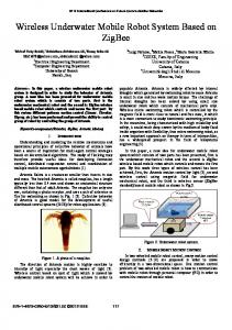
Finally, the received signal plus noise and interference is expressed as: r (t ) = v(t ) + n(t ) + j (t ) (4) where n(t) is the additive white Gaussian noise (AWGN) and j(t) is a narrow band interference (NBI). The last term is considered because NBI like radio and television broadcast, cellular phones, emergency systems and others exist in the selected band. Fig. 1 shows an example of received pulse train after channel convolution, for distance: d=[10.81;4.12; 9.80;9.0], where di is the distance between BSi and MR.
Figure 1. TDMA frame and base station slots
III.
SENSOR ARCHITECTURE
The UWB TOA algorithms are usually based on match filter (MF) or energy detector receivers. These algorithms estimate the time that maximize the correlation at the MF output or the time of the maximum energy sample [8,9]. The main drawback of this type of maximum likelihood (ML) estimator is that in Non Line of Sight (NLOS) condition the direct path signal is not the most powerful, so the estimated time is erroneous. In order to avoid this problem different signals metric are used for optimum threshold setting [10, 11]. Generally, a threshold based TOA algorithm, select the optimum signal value that minimize the TOA error. In this paper a TOA estimation algorithm based on a new metric for dynamic threshold setting that reduces errors in NLOS situations is suggested. On the other hand, a Wavelet Cyclic Cross Correlation Receiver (WCCC) was designed, which enhances the signal to noise ratio and improve the signal leading edge detection. In UWB systems, not only the signal parameter, but also the signal shape can be modified during radiation and reflection from different objects or people inside the environments. The lack of a priori information on signal parameters makes it impossible to describe such a signal analytically or introduce some a priori information in the receiver structure; therefore MF is not recommended for UWB signal detection. The only a priori information that can be used is the pulse repetition period Tr. Analyzing (1), it is possible to see that this period is equal to the length of TDMA frame. The authors
propose the use of a modified optimal receiver architecture called Inter Period Correlator Processor (IPCP). The efficiency of IPCP depends on the MR velocity and channel variation during Tr. Considering that the total symbol length after TDMA is Ts=Tr.Nf=9.8us, the channel will be unmodified due to MR movement, because the robot maximum velocity is on the order of one meter per second. Moreover, the channel coherence time is greater than Ts, so it can be considered that all frames are affected by the same channel characteristics. The received signal r(t) is correlated with a delayed signal coming from the same BS. This correlation improves the signal to noise ratio (SNR) because the noise and interference at the correlator input are not correlated since they are acquired on different periods or TDMA frames. Furthermore, the signals are scattered by the same objects or building furniture and modified by the same communication channel, so they are highly correlated. A detailed analysis of probability density function of signal and noise at the IPCP output can be found in [12].
wavelet transform is used as a filter bank. The wavelet transform has been used in previous TOA estimation work, but in the form of multi scale product or for denoising proposes [14, 15]. To preserve the correlation dimension at multiple scales, the concept of Mallat-Zhong discrete wavelet transform (MZDWT) is applied for filter coefficient generation [16]. The wavelet packet transform (WPT) is used for evaluating different wavelet mothers such as Daubechies, Coifman and Haar at different scales. The Haar wavelet is selected for its edge detection capacity and for its simple implementation. The filter coefficients of a WPT are calculated following the concept of MZ-DWT for filter impulse response generation. The resultant filtered signal is:
ys [n] = ∑ r[n]h[n − k ]
(6)
k
where h[n-k] is the wavelet filter impulse response.
The accuracy of the proposed receiver is related to the capacity of making a precise delay Tr. Since it is difficult to make an accurate analog delay, the authors used the model of Digital Receiver, in which the analog to digital converter (ADC) is placed as close as possible to the antenna. The simulations were done considering that only one ADC sample r(t) at 1Gsps. This selection is based on the aim of design a low cost and low complex UWB receiver. Is important to mention that Nyquist sample rate is accomplished because the UWB pulse has 500 MHz bandwidth at -10dB.
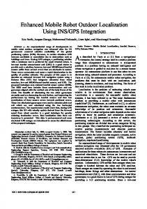
This filtered signal is the input for CCC, so the final receiver architecture and TOA estimator is shown in Fig.2.
The simple cross correlation function is not useful in our scenario, because the received signals have very different power levels; as shown in Fig. 1. Normalized output is required to facilitate the identification, so the correlation in the IPCP is replaced by Temporal Coherence Function (5), that takes the same value of correlation coefficients when the received signals are zero mean. This gives a normalized value that will permit identification of multiple signals with different SNR.
In order to identify the multiple transmitting base stations a Sliding Correlation (SC) between the CCC output u[n] and each BS Gold sequence is calculated. The SC output provides a set of signals, one per BS, defined as uBS[n] that will be the input for the TOA estimator.
γ xy =
Rxy (τ ) Rxx (τ ).Ryy (τ )
(5)
The General Cross Correlation (GCC) criteria proposed in [13] shows that pre-filtering the signals before cross correlation improves the accuracy of the TOA estimation. On the other hand, it is possible to get a Maximum Likelihood (ML) estimator if proper filter is selected, under signal and noise Gaussian assumptions. The main problem of this estimation criterion is that independent of the selected filter or weighting function; if there is a NBI that covers the same spectral band, the GCC can do nothing to reduce the interference effect. However, the transmitted signal is clyclostationary so the cyclic counterpart of GCC, called Cyclic Cross Correlation (CCC) is implemented. Due to this cyclic characteristic, the CCC receiver rejects the NBI, and is affected only by those NBI that have the same cyclic characteristics. The CCC fails when the SNR is low or when the received signal is very scattered. In order to reduce the noise component and improve the edge detection of the received signal, a
Figure 2.
Wavelet Cyclic Cross Correlation Receiver and TOA Estimator
IV.
TOA ESTIMATION ALGORITHM
As mentioned in the previous section, the simplest TOA method consists of selecting the time that maximizes the cross correlation signal uBS[n] at the SC output. This method works well under high SNR and LOS conditions, but in other cases, this estimator has a bias that produces a great error in the localization system. A threshold based TOA algorithm, selects the time at which the signal at the receiver output crosses an established threshold. The estimation accuracy depends on the threshold selection. If the threshold is low, the probability of detecting a peak due to noise increase, it is defined as false alarm or early detection. Whereas, if the threshold is high, probability of detecting a signal that arrives later than the direct path (DP) increases, this is called miss detection. Analyzing the coherence function output, it is possible to see that when there is a high SNR and LOS, the slope of u[n] is high. On the other hand if there is low SNR and NLOS condition, the u[n] slope decreases. With the intention of selecting a dynamic threshold that works well under different SNR and LOS conditions, a new metric that is based on the slope measurement of two consecutive samples at the SC
output, uBS[n] is proposed. In (7) and (8) the cumulative slope of two consecutive samples is defined.
∆u[n] = u[n] − u[n − 1] ξ [n] = ∆u[n] − ∆u[n − 2] + ξ [n − 1]
(7)
(8) The dynamic threshold is calculated as the root mean square (RMS) over a sliding window of length Tw-th, as it is expressed in (9).
θ [n] = RMS (ξ [n]) =
1 Tw _ th
n
∑ (ξ [n])
2
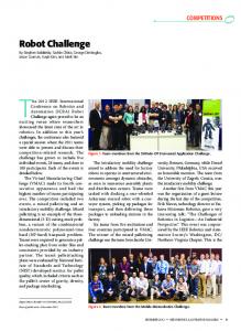
some timing bias on the BS transmitted signals, the difference operation permits its cancellation when errors are similar. As mentioned in Section I the position estimation is made by the mobile robot itself, because of that, the position algorithm is classified as self-localization two step method. The mobile robot estimates the ranges multiplying the time difference measured with the radio speed (13). These ranges produce a set of hyperbolas and its intersection determined the MR position, Fig 3.
(9)
i = n −Tw _ th
When the value of ξ[n] is greater than θ[n], means that a significant change in the signal to noise ratio at the SC output takes place, so there is a possibility that a direct path signal has arrived. The algorithm chooses as a possible DP, the time at which a dynamic threshold θ[n] is overcome.
nDP = {n / ξ [n] > θ [n]}
(10) Due to noise and interference there are estimated DP that appear later than the true direct path, so miss detection is increased. With the aim of reducing this problem the algorithm consider only the nDP that happens when the signal uBS[n] is below a fixed threshold. On the other hand the SC peak nPK is determined when the slope ξ [n] decreases. Finally, the algorithm selects the DP time that minimizes the difference between the nPK and all possible estimated direct paths time, as shown in (11).
nˆTOA = arg
n DP
min{nPK − nDP }
(11)
In industrial environments the NLOS conditions are always present and the estimated time generally has a positive bias. There are two situations that produce such bias, the first one happens when the direct path, between the robot and base stations, is completely blocked and cannot be detected. The second one takes place when the signal is delayed because it travels for different propagation environments, e.g. different wall materials. Hence, in NLOS situation even if the direct path is correctly estimated, there is a positive bias that must be corrected. Some work tries to identify LOS and NLOS conditions using different signal statistics with the aim of correct the bias [17], and other recent works tray to model the bias [18]. The simulations have shown that for different NLOS situations and SNR, the TOA algorithm produces similar bias, which indicates a good lower bound variance. This characteristic is very important when the time estimation is used on TDOA algorithm, as will be explained on the next section. V.
POSITION ESTIMATION ALGORITHM
The localization system is classified as “two step positioning system”. In the first step, the algorithm estimates the signal TOA, as explained in the previous section. In the second step, the position is estimated using a TDOA technique. The TDOA ranging method does not require knowledge of transmission absolute time, therefore only the synchronization required for TDMA is necessary. On the other hand, if there is
Figure 3. TDOA localization system and hyperbolas set.
In a 2-D position localization system, the base station position is expressed as (Xbs,Ybs) and the mobile robot location is (xR,yR). The distance between the BS and the MR is:
( X bs − xR )2 + (Ybs − yR )2
Ri =
(12)
The range difference between the base stations is:
Ri ,1 = c τ i ,1 = Ri − R1
(13)
Ri,1 = ( Xi − xR ) + (Yi − yR ) − ( X1 − xR ) + (Y1 − yR ) 2
2
2
2
(14)
where c is the radio speed and τ i ,1 is the TDOA estimation between station “1” and station “i”. If there are NBS base stations there will be NBS-1 non linear hyperbolic equation to solve. Several algorithms had been proposed to solve these nonlinear equations [19, 20]. If the set of nonlinear hyperbolic equations equals the number of unknown coordinates of the source, then the system is consistent and a unique solution can be determined from iterative techniques. The proposed 2-D localization model is an inconsistent system, because redundant range difference measurements are made. Classical techniques for solving these equations include the Least Squares (LS) and Weighted Least Squares (WLS) methods. If the range difference errors are uncorrelated and Gaussian distributed with zero mean and equal variances, then the LS solution provides the maximum likelihood (ML) estimation. However, a problem exists because the variances are either not known a priori or difficult to estimate. A noniterative solution to the hyperbolic position estimation problem which is capable of achieves optimum performance for arbitrarily placed sensors were proposed by Chan [21]. The solution is in closed-form and valid for both distant and close targets. When TDOA estimation errors are small, this method is an approximation to the maximum likelihood (ML)
estimator. The authors use the method proposed by Chan because it is simple to implement, requires low processing time and achieve accurate results. VI.
EXPERIMENTAL SETUP AND
SIMULATION RESULTS
For algorithm evaluation paths A and B were simulated considering the dimension and furniture characteristics of Institute of Automatics. In Fig. 4 the base stations and path positions are shown with all distances expressed in meters. The positions in path A are marked as “+”, begin at point (1,9), turn around the library and return to same point. The positions on path B are marked as “o”, begin at point (2,5) and finish at point (11,5). Path B was simulated in order to evaluate the algorithm performance when there is NLOS condition for all base stations. This is important to mention because TDOA position estimation algorithm depends on the number of reference nodes with LOS [22].
was repeated 3 times, this gives a total of N=1056 simulated channels. The path B has 67 positions and the experiment was done 4 times, that gives a total N=1072 simulated channels. The NBI term j(t), is considered as a frequency modulated (FM) broadcast signal at 100Mhz with -45 dBm/Mhz of power. The Fig. 5, shows the real position of path B and the estimated ones. It is possible to assert that the proposed estimation algorithm and receiver structure achieve good accuracy except for some estimated positions in which the errors are greater than 0.6 meters. The occurrence of these errors generally happens because the SNR is very poor and it is so difficult to determine the true direct path at the correlator output.
Figure 5. Path B true vs. estimated positions Figure 4. Position in meters for Path A and Path B
The most commonly used measure of accuracy on position estimator is the contrast of its mean squared error (MSE) with the theoretical MSE based on the Cramer Rao Lower Bound. The TOA algorithm produces a bias estimate, as explained in the previous section, moreover the signals are non-stationary and the noise is non Gaussian, so it is difficult to get the CRLB for this type of estimator. Therefore, the localization algorithm is evaluated calculating the root mean square error (RMSE) between the estimated position and the real one. Another important measure that is used for evaluating the proposed localization system accuracy is the Circular Error Probability (CEP). This measure the estimation uncertainty related with the mean value. For a 2-D system, the CEP is defined as the radius of the circle that contains half of the estimations with the mean as its center. If the TOA estimator is unbiased, the CEP is a measure of the uncertainty relative to the true transmitter position. If the estimator is biased and bound by bias b, then with a probability of one-half, a particular estimate is within a distance b +CEP from the true transmitter position [23]. The CPE is generally approximated and can be expressed by the following equation:
CEP ≅ 0.75 * σ x + σ y 2
2
(15)
where σx2 and σy2 are the variance of the estimate position. For simulation purposes the received signal is generated as (4) and one channel is simulated for each BS and path position. In the case of path A there are 88 positions and the experiment
With the aim of demonstrating that errors greater than 0.6 meter have very low probability of occurrence, Fig 6 shows the cumulative density plot (CDF) for the absolute error between the estimated and real position in both coordinates, for path B.
Figure 6. Path B CDF position absolute errors
Finally, on Table I the RMSE and the mean CEP value for path B are expressed. TABLE I. Path B Mean value
RMSx (m) 0.1961
RMSy (m) 0.1812
CEP (m) 0.1639
Path A simulations are used for evaluating the robustness of TOA estimator algorithm. The absolute errors of estimated TOA were calculated for different noise powers: SNR1:60dBm/Mhz, SNR2: -57dBm/Mhz and SNR3:-55dBm/Mhz.
The CDF plot, Fig. 7, shows that the proposed algorithm works well under different SNR conditions.
[4]
[5]
[6] [7]
[8]
[9] Figure 7. Path A CDF for different SNR.
It is possible to determine that errors greater than 2ns, which translate to position errors bigger than 0.6 meter approximately, are more common in Path A than in Path B. This happens because Chan’s method is more accurate when the estimated errors are small compared with the measured range, so errors between 0.6 and 1 meter happen near the base stations. It is important to mention that the proposed algorithm uses only one TDOA estimation for localization. It is possible to attain better results if more TDOA measures were evaluated for the same position and iterative algorithm was used. This also increases the computation complexity and constrains the mobile robot maximum velocity. VII. CONCLUSIONS This work proposes an accurate indoor localization system for mobile robots. The UWB sensor does not depend on calibration or environment conditions like other mentioned sensors, so it is more robust than conventional sensors for position estimation. On the other hand if a transmitter is mounted on the robot, the receiver can be used as radar and it will be possible to map the environment, so that position estimation and mapping can be made with the same UWB sensor. Another advantage is that with the same network structure it is possible to estimate the position of multiple robots and coordinate tasks in cooperative work. In this paper a modified version of IPCP receiver with wavelet filter and dynamic threshold selection have been proposed for UWB signals TOA estimation. In future work the author will implement the designed algorithm on FPGA from Xilinx and 1Gsps ADC from MAXIM in order to carry out real experiments. REFERENCES [1]
[2]
[3]
Neal Patwari, Joshua N. Ash, Spyros Kyperountas, Alfred O. Hero, Randolph L. Moses, and Neiyer S. Correal, “Locating the node” IEEE Signal Processing Magazine, vol. 22, pp. 54-69, Jul. 2005. Sinan Gezici, Zhi Tian, Georgios B. Giannakis, Hisashi Kobayashi, Andreas F. Molisch, H. Vincent Poor, and Zafer Sahinoglu, “Localization via Ultra-Wideband Radios,” IEEE Signal Processing Magazine, vol. 22, pp. 70-84, Jul. 2005. Krishnan S., Sharma P., Zhang Guoping, Ong Hwee Woon, “A UWB based Localization System for Indoor Robot Navigation Ultra-
[10]
[11]
[12] [13] [14] [15]
[16]
[17]
[18]
[19]
[20]
[21]
[22]
[23]
Wideband” , IEEE International Conference on Ultra-Wideband, pp. 77 -82, Sept. 2007. Schroeder J., GallerS., Kyamakya K., “A low-cost experimental ultrawideband positioning system”, IEEE International Conference on UltraWideband, pp 632-37, Sept. 2005 Mark Jamtgaard, “Sub-GHz_Overview”, IEEE P802.15 Working Group for Wireless Personal Area Networks (WPANs), Doc: 802.15-05-039000-004a. Moe. Z. Win and Robert. A. Scholtz, “Impulse Radio:How its works,” IEEE Communication Letter, vol. 2, nº 2, pp. 36-38, Feb 1998. Dajana Cassioli, Moe Win, Andreas Molisch, “The Ultra Wide bandwidth Indoor Channel: From Statistical Model to Simulations”, IEEE Jornal on Selected Areas in Communications, vol. 20, nº6, pp 1247-1257, Agu. 2002. Woo Cheol Chung, Dong Sam Ha, “An accurate ultra wideband (uwb) ranging for precision asset location”, IEEE International Conference on Ultra Wideband Systems and Technologies, pp. 389-393, Nov 2003. Rabbachin, A., Oppermann, I., Denis, B., “ML Time-of-Arrival estimation based on low complexity UWB energy detection Ultra-Wideband”, IEEE International Conference on Ultra-Wideband, pp. 599- 604, Sept. 2006 . Guvenc, I., Sahinoglu, Z., “Threshold-based TOA estimation for impulse radio UWB systems Ultra-Wideband”, IEEE International Conference on Ultra Wideband, pp 420-425, Sept 2005. Shaohua Wu, Qinyu Zhang and Naitong Zhang, “A Two-step TOA Estimation Method for IR-UWB Ranging Systems”, Fifth Annual Conference on Communication Networks and Services Research, pp. 302-310, May 2007. James D. Taylor, “Ultra-WideBand Radar Technology”, CRC Press, Boca Raton, Florida, 2001. ch 2. Clifford G. Carter, “Coherence and Time Delay Estimation”, Proceeding of the IEEE, vol. 75, nº 2, pp 236-255. Feb. 1987. I. Guvenc, Z. Sahinoglu, “Low Complexity TOA Estimation for Impulse Radio UWB Systems”, Mitsubishi Electric Research Labs, 2005. Chen Y. and An J. P., “UWB signal generation, acquisition and processing using wavelet functions”, IEEE Third International Conference on Ultrawideband and Ultrashort Impulse Signals, pp. 329331, September, 2006. Stephane Mallat and Sifen Zhong, “Charaterization of signals from Multiscale Edges”, IEEE Trans on Patern Analysis and Machine Intelligence, vol. 14, nº 7, pp. 710-732. Jul. 1992. Ismail Guvenc, Chia-Chin Chong, FujioWatanabe and Hiroshi Inamura, “NLOS Identification and Weighted Least-Squares Localization for UWB Systems Using Multipath Channel Statistics”, EURASIP Journal on Advances in Signal Processing,Vol. 2008. González J., Blanco J.L., Galindo C., Ortiz-de-Galisteo A., FernándezMadrigal J.A., Moreno F.A., Martínez J.L., “Mobile robot localization based on Ultra-Wide-Band ranging: A particle filter approach”, Robotics and Autonomous Systems, Elsevier, Vol 57, Issue 5, pp 496-507,31 May 2009. Bertrand ‘E Fang, “Simple Solutions for Hyperbolic and Related Position Fixes”, IEEE Trans on aerospace and electronic systems vol. 26, no. 5 Sep 1990 Julius Smith and Jonathan Abel, “Closed-Form Least-Squares Source Location Estimation from Range-Difference Measurements”, IEEE transactions on acoustics, speech, and signal processing, VOL. ASSP35, NO. 12, Dec 1987. Y. T. Chan, Senior Member, IEEE, and K. C. Ho, Member, “A Simple and Efficient Estimator for Hyperbolic Location” IEEE Transactions On Signal Processing, Vol. 42, nº 8, pp 1905-1915 Aug. 1994. Xu J., Ma M., Law C.L., “Position Estimation Using UWB TDOA Measurements, IEEE International Conference on Ultra Wideband Systems and Technologies, pp 605-610, Sept. 2006 D. J. Torrieri, “Statistical Theory of Passive Location Systems," IEEE Transactions on Aerospace and Electronic Systems, Vol. AES-20, No. 2, pp.183 - 198, Mar 1984.