%~h%%~@$%% BgJ$kke $d~ - 19H. qW$?iA
Proceedings of the 5" World Congress on Intelligent Control and Automation, June 15-19, 2004, Hangzhou, P.R. China
2 0 0 4 q 6 f l 15
Robust Mobile Robot On-the-Fly Localization: using Geometrical Feature Matching Method* Yingjie Sun and Qixin Cao
Jay Lee
Research Institute CfRobofics Shanghai Jiao Tong University Shanghai, 20030, China
Intelligent Maintenance Systems University of Wisconsin Milwaukee, 53201, USA
{yjsun & qxcao}@sjtu.edu.cn
[email protected]
Abstract - Self localization is an essential component of any autonomous mobile robot system. This paper presents a fast and robust feature-based approach to mbbile robot on-the-fly global localization in dynamic environments. A robust feature extraction and correspondence algorithm was introduced to extract the landmarks of the environment and to triangulate the robot's positions. The approach take into account the hard real time constraint and the partial ohservahility of the environment. Online localization is performed by matching candidate landmark from the robot's lcoal view to the tracked landmarks. Experimental validation in the context of Middle Size League RoboCup was carried out in a real environment with the mobile robot Jiaolong which equips a Laser Range Finder (LRF). Index Terms - On-the-fly localization; Feature extraction and correspondence; Geometrical feature matching; Landmark Detection, Laser Range Finder. 1. INTRODUCTION
Localization is an essential area of mobile robotics that has received increased attention over the past decade [l]. Localization is the process of determining the robot's position within a given environment, and it is a procedure that takes a set of sensor readings and/or a priori map as input and gives an estimate of the robot's pose. Navigation is a fundamental problem for autonomous mobile robots and it relies highly on robust localization methods [2].The use of a particular kind of sensor usually affects the design choices for localization method. There are many successhl localization methods that are able to determine a robot's position relative to a map using odometer, sonar, Laser Range Finder and camera [2, 31. Localization methods are discriminated as relative and global localization. Relative localization method generally employs proprioceptive sensors (e.g. odometer, inertial sensor and gyro) to estimate the robot motion, and to update the robot's location. Dead reckoning based techniques are impractical because the systematic and nonsystematic measurement errors grow without bound due to the slippage and collision. The problem of global localization is to estimate the correct pose of a mobile robot with respect to some global reference frame from little of no a priori position and orientation.
Geometrical approaches require a comparison between the local geometry model extracted from the sensor information with a priori environment. Feature based localization is an extensively used geometrical method [4, 51. The process of feature extraction and correspondence must be executed on line while the robot is moving. Feature based localization uses natural environment features as landmarks. This approach has extensively studied for navigation in indoor environment. Although Hough Transform is an effective method for detecting lines and curves from noisy data it has the drawback of sensitive to the resolution of the discretization resolution [6].A Laser Range Finder is often employed to build a local map which is matched to a global reference map in order to estimate the actual pose ofthe robot [7, 81. However most of the proposed solutions do not take into account some real constraints encountered in practical applications. This paper describes an algorithm by which a robot can construct a map on the fly and localize itself in the context of Middle Size League RoboCup considering that the robot motion planning bas to require no human intervention during the robot soccer game. Robust localization is the problem of determining the pose of a mobile robot with respect to a global or local frame of reference in the presence of sensor noise, uncertainties and potential failures. A robust and accurate determi,nation of location is fundamental for the motion control of mobile robots. In this paper a robust feature extraction and correspondence algorithm was used to extract the rich features i.e. landmarks from the environment and the landmarks triangulated the robot's positions. .The approach constantly updates the robot's pose relative to a global frame i.e. the robot soccer field. The purpose of the landmark detector is to locate candidate landmarks in a range image. These candidates are later provided to the tracker for the purposes of building a set of tracked 1andmarks.Thisapproach has extensively studied for navigation in indoor environment [7, 8, 9, IO]. However most of the proposed solutions do not take into account some real constraints encountered in practical applications. Self localization methods for mobile robots need to take various sources of uncertainty into account in order to get robust performance. In this paper, we presented a robust feature extraction algorithm and the matched feature acquired by a Laser Range
This work is partially supported by NNSF of China Grant #50128504 (Young Oversea Investigator Award) and #50390063 to Qixin Caa and Jay Lee.
4749
0-7803-8273-01041$20.00 0 2 0 0 4 IEEE
Finder is used to estimate the robot pose. The main challenge in this work was on choosing feature representation for many types of geometrical feature. With such representation it is possible to solve pose estimation by means of feature transform. Because map matching is essential for pose estimation, a feature extraction and correspondence algorithm is discussed in a split and merge framework. In this phase we attempt to find a list of local and global features. The approach to find feature correspondences is implemented by a sliding window with a given width. We further addressed the issue of pose estimation employing the list of matched feature. On-line localization is performed by matching candidate landmarks from the robot’s current view to the tracked landmarks, and interpolating a parameterisation of the set of tracked candidates. Further, experimental validation was carried out in a real environment with the mobile robot Jiaolong. This rest of the paper is organized as follows: Section I1 gives a detail description of the hardware system and sensor configurations. Section 111 presents the feature extraction and correspondence algorithm, geometrical feature mapping algorithm and self localization algorithm. The experiment results are described in Section IV. Section V gives a discussion and concludes this paper. 11. MOBILEROBOT AND SENSOR CONFIGURATION
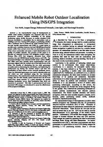
For the Middle-Size League RoboCup, we have developed autonomous mobile robot Jiaolong and a laser range finder is mounted on top of the robot as shown in Fig. 1. The Laser Range Finder used for local map building is a LMS 200 manufactured by SICK Optic Company. In this experiment its maximum range is set to be 8000mm, with a statistical error +/- 15nun. This sensor provides scans in 1 8 0 ~ angular field with a resolution of 1’ through its RS232 interface with 19200 baud and the frequency is about 5Hz.
I
.-
I
111. ALGORITHMS
A geometrical feature is a special type of target that can be reliably observed in successive sensor measurements and that can be accurately described in terms of a concise geometric parameterization[l 11. Feature based localization uses natural environment features as landmarks. In order to estimate the pose of the robot, using Laser Range Finder to build a local map has been extensively studied for navigation in indoor environment [7, 81. However most of the proposed solutions do not take into account some real constraints encountered in practical applications. In the field of RoboCnp Middle-size league, the wall of the goal, the goal posts and the comer posts can be used as landmarks. Due to the limitation of Laser Range Finder’s view angle, the posts are only partial observable in some occasion. The comer posts are easily confused with the people so it is not meaninghl and reliable to employ comer posts to localize the robot. During the robot soccer game the robot motion planning has to require no human intervention. The real robot soccer field is dynamic and adversarial. Assuming that no collisions occur is unacceptable, while the dead reckoning may generate unbounded error due to the wheel slippage and collision. Landmarks are easily occluded by other robots in the soccer game. Therefore the robot must consider the collisions and occlusions in order to get real time robust performance.
A. Feature Detection Using Feature Transform First we transform the polar coordinate Cartesian
coordinate
system
( x j ,y,)
O(q,@) into 1
where
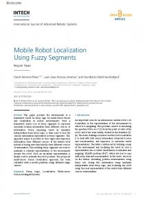
xi = q cos8,,yi = q sin 0, (Fig. 2). Next we calculate the forward deference:
sx; = xi -xi+?, 6y’ = yi - yito,
(1)
and backward deference:
6 X bi = xi - xi-s, 6 y b, = yi - yi&v, on
(2)
( x i , y i ). The range image is divided into intervals with
step length 17 which is decided by the sensor uncertainty field. The Feature Transform is defined as follows:
sx;.= sx/ - 6xp, 6yJ = 6y’ - 6yp
(3)
B. Split-and-Merge Feature Extraction Algorithm Once the original data is mapped into feature space, the eigenvalue of the intervals are calculated to discriminate different types of geometrical features, which are then used to registry the features in the whole map. In order to improve the robustness of the feature transform and consider the sensor uncertainty implicitly we use an observing window with k width. The eigenvalue in the sensor feature space is defined as itk
6x;. 6y;.
F; = ~
.,=I
where k is width of the observe window Fig. 2 Laser Range Finder data
4750
(4)
The feature type of the interval is decided by its threshold and the precise position of the feature point is calculated by:
E, = arg max 1 6.x; ' 6 y ; 1.
(5)
ie[j,j+k]
In order to unify the feature extraction algorithm into a framework we employ the multi threshold method.
C, = {ie I I E, A 6yi 5 0 A (4 t T,,,,)} E, = {i€ I I A (Fi2 TEdze) V (Fi5 -%dge)} S, = {i E I I (Tconmet Fl t TSegenmenO v (-Tsepenmeni 2 F; 2 - T ~ m c o v e ) } A?,
(6)
(7) (8)
S,=S,+k (9) Where C, is index of the concave comer, E, is index of the edge,
s,
and
se are the
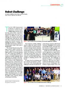
beginning and end index of the Fig. 4 Eigenvalues of feahlre extraction
segments. The above detail geometrical features are essential for the geometrical reasoning. The splitting phase (See Fig. 3) starts from (Yo,&) taking the whole range image as candidate and split the raw range data according to the step length 7.After the Feature Transform and the multi threshold segmentation, the interval's type is decided by the Feature Transform and its eigenvalue. Feature vector 1s defined as
L,(i = O,L...,n) = (OjBegjn,OjEnd,F), where
~ ,
and
(10)
are the beginning and end index
Fig. 5 Extracted features ofthe environment
s)
AAer the spilt loop we merge adjacent candidate intervals if they are homogenous and extract task-specific knowledge (comers, straight lines, edges etc). The concave comers are extracted by the multi threshold segmentation and their positions are also decided. At the same time the property of the geometrical feature could be calculated. It merges segments until their eigenvalues are greater than a threshold. The detail algorithm is shown in Fig. 3.
of the feature respectively. F E (U,E , C , represents the different feature types. Where U represents that feature of interval is undecided; E represents that feature of interval is Edge; C represents that feature of interval is Concave: S represents that feature of the interval is Segment, Jgorithm: Split -and - Merge0 { 0 Given LRF range data,start from(r0,8,);
C. Geometric Calculations
1 divide the image into [ 1 8 0 / ~ intervals ] ; 2 perform Feature TranSfonn and calculate the eigenvalue; 3 extract feature using multi threshold segmentation: 4 if the interval's feature k; = C then registry a concave comer
to the robot, i.e. A P ( Y A , O , ) and BP(V,,O,) in Fig. 6, and
5 if 4 = S A