Mockup-driven Fast-prototyping Methodology for Web Application Development Jia Zhang infiNET Solutions Buffalo Grove, IL 60089
[email protected]
Jen-Yao Chung IBM Watson Research Yorktown Heights, New York 10598
[email protected]
Abstract
Web application development can be very complicated without an appropriate framework, architecture and application model. A good implementation model can help application developers communicate with clients, consolidate the design before starting the development, speed up the development, and make the code highly reusable. This paper proposes a mockup-driven fast prototyping methodology (MODFM) for the development of web applications. It is built on the most recent web technologies: EJB, JSP, Servlet, XML, Struts, and web application server.
A two-tier Model-View-Controller (MVC) architecture is
proposed as the underline backbone and a supporting environment is tailored specifically in order to enable development. Two basic supporting tools are provided: the dynamic menu generator and the generic code generator, which produce code for front-end, back-end and database schemas. MODFM helps to generate fully functional mockup systems for the client to review at an early analysis stage, and continues to provide guidance throughout follow-on development phases. Real-life experiences on the use of this methodology in industry are presented as examples.
Keywords prototyping of web applications, generator, architecture, supporting environment, mockup
1. Introduction
In the broadest sense, a web application is an application combining computing and networking technologies to facilitate communication through the Internet. One can envision a web application as a traditional client/server application published on the web with a web interface.
Embracing many
1
disciplines, the development of a web application can become a very complex, costly and time-consuming task, if not supported by a practical methodology [1]. According to Sommervill, one of the key concepts in software engineering is client-centrism [2]. It is software engineers’ responsibility to ensure clients’ confidence on an ongoing project; and clients would normally gain more confidence about a designed application if they could visualize it. In addition, given that user interaction in web applications is through web browsers, the design of appropriate user interfaces is of paramount importance. Therefore, the concept of prototyping is extremely appealing for web applications.
Szekely states that prototyping involves constructing a small-scale version of a complicated system in order to acquire the critical knowledge required to build a full system [3]. Often a prototype will only contain user interface and partial functionality. Using Bochicchio’s definition, prototyping in web applications means a fast, cheap, and reliable development of a mockup of the final application system [4]. According to The American Heritage Dictionary, a mockup is “a usually full-sized scale model of a structure, used for demonstration, study or testing” [5]. A mockup can not only provide clients a complete picture of what the final product will be, but also facilitates design checking, testing, discussion, and revision. Building a mockup has several apparent advantages. First, a mockup exhibits to customers the current requirements gathered.
It enables customers to evaluate the requirements, refine the requirements, elicit new
requirements, and finalize the requirements. Second, the iterative process of mockup constructions and revisions reveals to customers an outlook of the final system; therefore, customers would be confident of the application being built. Third, since a mockup will become the skeleton of the final system for the development, no work will be thrown away. Fourth, a mockup helps finalize the system requirements; thus no backward rework needs to be done after a mockup is accepted by clients. A mockup minimizes the risk of wasting valuable development efforts because of ambiguous or incomplete requirement specifications. Fifth, a mockup can be reused by other similar applications since it does not involve much business logic.
In this paper, we define a development methodology for the development of web applications, which is referred to as web engineering [6][7].
The methodology is called MOckup-Driven Fast-prototyping
Methodology or MODFM. MODFM comes in play in the web engineering life cycle when a primitive
2
analysis document has already been produced from the initial requirements analysis. Our methodology has several goals. First, we seek to expedite the development of web applications by exploiting automatic program generation techniques. Second, we wish to include customer feedback early in the development process. Requirements for web applications are often fluid and changeable. By involving customers early on, we minimize the risk of wasting valuable development efforts because of ambiguous or incomplete specifications. Finally, we seek to facilitate software maintenance. Web applications must often be modified quickly in response to evolving user requirements.
We accomplish our goals in several ways. First, MODFM incorporates techniques for automatic code generation in order to expedite application development. The Web Generation (WebGen) toolset contains two code generators. The Generic Generator (GG) tool automatically generates a skeleton application (i.e., a mockup) that contains the interface, but not the full functionality, of the finished application. The Menu System Generator (MSG) tool automatically generates the menu displays of the application. Second, we define software architecture suitable for a broad variety of J2EE-compatible web applications.
Our
software architecture divides a web application into two main components, a front-end subsystem and a back-end subsystem. Our methodology and tools lead to the creation of web applications conforming to this architecture. Third, MODFM proposes a systematic procedure to guide web application development. Fourth, MODFM seamlessly integrates cutting-edge technologies for web development, such as J2EE and XML, with established development methodologies, including rapid prototyping and automatic code generation. Utilizing well-tried concepts, such as client-centric development [2] and rapid prototyping [3], MODFM seeks to gain customer feedback at early stages of development in order to avoid wasting development efforts because of incorrect or incomplete specifications. Through an automatically generated mockup, customers can glean the functionality of the finished application early in the development cycle. In addition, MODFM relies on the Model-View-Controller (MVC) paradigm [8] for the design of the frontend and back-end subsystems; this paradigm is known to facilitate maintenance by separating the code for modeling the application domain from GUI code.
3
The rest of this paper is organized as follows. In section 2, related work is discussed. In section 3, we present the web code generator. In section 4, we introduce a two-tier MVC architecture. In section 5, we describe a supporting environment tailored for the architecture. In section 6, we propose our mockupdriven fast-prototyping methodology. In section 7, we discuss the development of a real-world application, as an example to explain how to construct a mockup system using MODFM. In section 8, we summarize the contribution and innovation of MODFM, discuss assessments, and describe future work.
2. Related Work
Model-driven methodology has been used to simplify and automate the development of web applications. Among the abundant efforts, HDM [9] proposes a popular model descended from Entity-Relationship Model [10] for hypermedia application design, which divides conceptual schema into two categories: structural and navigational. Autoweb [1] utilizes a variant notation of HDM called HDM-lite, by adding a presentation schema, to conceptually design the web application, and store the conceptual schema together with data content in the database. Jweb [4] provides a design/prototyping environment, integrating XML technology with HDM to help design the conceptual schema. UML has been popular to model software applications. Conallen [11] extends UML notation to model web specific elements, thus makes it possible to model the whole web application with UML.
RMM [12] is a database-driven methodology for
structured hypermedia design. Its principle idea is to provide a visual representation of the system in order to facilitate design discussions. It also suggests an iterative process to decompose visual components to database relationships. Gaedke [7] utilizes WebComposition and WebComposition Markup Language (WCML) [13] to present a systematic approach for code reuse in component-based web applications. IIPS [14] models navigational structure, compositional structure, and user interface through ontology, and provides tools for code generation. Web Modeling Language [15] is a notation of designing a complicated web site at the conceptual level, which defines a web site along five dimensions: data content, page composition, navigation links, page presentation, and customization features. All these efforts define techniques and tools to speed up the design and development of the web applications. Compared to them, our tools can help to generate a running web application from a set of XML configurations. These
4
techniques and tools were designed for developers who wish to structure their thinking, other than for clients who wish to see the interface. Therefore, existing techniques do not intend to yield a running mockup system to gather client’s feedback at the early phase. Furthermore, these techniques pay little attention to software maintenance. Little work addresses how to efficiently maintain the current code when it needs to be modified due to the client’s feedback.
Although object-oriented methods are dominant in software development in recent years, they do not provide step-by-step guidelines for decomposing a system [16]. Meanwhile, structured analysis is natural to human’s way of thinking. Moreover, in the real world, structured analysis is extensively utilized to partition the system into reasonably small subsystems before applying OO methodology. Functional decomposition is the essential technique in structured analysis serving to analyze complicated software applications. Its most famous representatives include Ed Yourdon’s [17] data-flow diagrams of top-down decomposition technique in the past, and its utilization in UML in the recent years. UML [18] has been widely believed to be the industry-standard design language [19] for specifying, visualizing, constructing, and documenting the artifacts of software systems.
Among its diagrams, the use case diagram and
sequence diagram can actually be considered typical structured analysis methods. We will use functional decomposition at the beginning of a web project to partition a system into subsystems organized by a hierarchical menu. An application server is a middle tier of enterprise software that brings together business logic and corporate data that reside in back-end systems and databases, and serves it up to the user at the front-end. Adopting an application server can avoid tedious coding of system level utilities, such as security, load balancing, and transaction integrity. Most of the available commercial application servers are based on Java 2 Platform, Enterprise Edition (J2EE) [20]. Struts [21] provides an open source unified front-end MVC [8] framework for web applications. There are three major components in Struts framework: a servlet controller that is provided by Struts itself, JSP pages or the "views", and the application's business logic or the "model". The servlet controller delegates HTTP requests to an appropriate handler, which is defined as an action object. The model represents an application's business logic or state and each handler is tied to a model. Control is then handed back through the controller to the appropriate view, usually
5
through a form bean that holds the information for the page. We adopted Struts to be the basis of our frontend model. This decision was driven by three factors. First, Struts combines Servlets and JSP techniques to provide a mature MVC implementation in web applications. Second, Struts is an open source software. Struts belong to the well-known Jakarta project, and detailed information can be found at http://jakarta.apache.org/struts. Third, Struts has been developed in the recent years with active developers and user communities.
3. Web Code Generator
Automatic code generation is becoming increasingly common and useful in software development, a result of the need to hide complexity from the software developers and the acceptance of various standards and de facto standard application programming interfaces. By using a code generator one can automate the process of some tedious, repetitive, and error-prone coding tasks. Thus, it will greatly reduce developers’ coding time and debugging time. As a result, software developers can concentrate on business logic and the development cycle can be greatly shortened. Furthermore, a code generator can be a timesaving tool that increases bug-free code quality, and introduces a more formal and automated approach to the development cycle.
J2EE has already been widely accepted as the essential infrastructure for web development.
The
formalized interfaces of its techniques make it extremely suitable for code generation. There are several code generation products and tools aiming at accelerating the development process of web applications [22].
Torrisoft is an on-going environment aiming at helping web site development utilizing Web
Modeling Language [15]. IIPS [23] provides a set of visual tools supporting web site generation from the conceptual design model. Some generation tools aim to help generate specific parts of a web application. CodeCharge [24] helps to generate front-end codes in selected languages such as ASP, JSP, and ColdFusion; KoolFrog [25] helps to generate PL/SQL routines from Oracle database; EJBGen [26] helps generating EJB 2.0 code. Visual Code-Generator [27] helps to generate code from ASP style scripts. Tekadence [28] offers a point-and-click programming interface and visual design tool to help build up Java
6
applications. GslGen [29] is a generic-purpose code generator from XML file and schema file using general-purpose schema language (GSL). Tekadence and GslGen generators are bound to specific script languages. JeeWiz [30] is a product that provides an environment to help generate code for J2EE-based web applications, such as EJB beans and deployment descriptor. Combining data and configuration in the same XML file makes JeeWiz less flexible to changes. It helps generate a skeleton code for middle-tier, but not for front-end and back-end artifacts such as JSP page and database schemas. Furthermore, JeeWiz does not contain a framework to link together different components generated, thus it is not suitable to generate a running application.
We are proposing here is a web code generator called WebGen. Compared to other code generators, WebGen provides a template system, specific to web applications, to generate a complete web system. In this paper, the term template is interchangeable with the term schema that is normally known in XML domain [31], in that they both describe a class of documents. We adopted the term template simply to emphasize that our template files are patterns of J2EE-compatible components.
Second, underlying
architecture provides a theoretical basis to group generated codes to become a running web application – we will discuss the architecture in detail in later sections. Third, the decoupling of data and configuration information makes the generation script easy to read and modify, and makes the data script highly reusable. Fourth, ample configurable features make WebGen powerful for generating code for extensive purposes. The separation of generated portion and immutable portion in one file provides the flexibility of regenerating a file without touching embedded business logic. Fifth, its menu system generator makes it possible to generate a completed mockup system. Sixth, WebGen is an automatic code generation tool integrated with XML technology, which is the universal format for structured documents and data on the web [31]. It accepts user input data information in XML format to generate target files. Seventh, WebGen can be used to generate many kinds of source code, including Java code, XML code, HTML code, JSP code, etc. Eighth, WebGen is not only efficient but also very easy to learn. The author taught a developer to use GG tool in 15 minutes and the person was then able to write GG scripts to generate code.
3.1 Generic Code Generator
7
Configuration File Data File
m:n
m:n
Template File
Figure 1. Relationship among components in GG generator
WebGen contains two code generators: generic code generator (GG) and menu system generator (MSG). GG generator comprises an essential class: GenericGenerator with a single public static method: generateCode(), and some utility classes. GG generator parses the following information provided by developers to generate code to the specified directories as desired: a list of template files; a list of XML data files; and an XML configuration file. The relationship between these three types of files is that, data file defines the data models that can be applied to template files to generate target file(s), and configuration files specifies the many-to-many relationship between them, together with some generation criteria. This relationship is shown in Figure 1. GG allows developers to provide template files, in accordance with common J2EE-required components, for the generation of web applications.
3.1.1 Data file
A data file is an XML file that describes the content of a data model to be merged into template files. Every data file is applied to template files to generate corresponding code. Figure 2 is an example of a data file that defines a data model of StudentGrade. As shown in Figure 2, for every item of the corresponding data model, one can define its name and data type. StudentGrade contains four data items: student id, year, term, and grade information. All four items have the same data type as “String”. The attribute Key is utilized to store the primary key internally. In addition, any aspect can be specified as an attribute of an item. For instance, as illustrated in Figure 2, the attribute Unique is utilized to specify whether the particular item can be treated uniquely or not; and attribute Valid is utilized to specify whether the corresponding validation code needs to be embedded into the generated files.
8
Figure 2. A simple example of a data file StudentGrade.xml
3.1.2 Template file
A template file itself is a code file, which contains tags that must be replaced at generation time by the corresponding values from the data files. Figure 3 is a simplified template file for a Java bean class. It can be used to generate a fully functional Java class file, which comprises a constructor and a set of getters and setters. GG defines three categories of tags: simple tag, repeating pattern, and conditional. A simple tag is a single tag, which will be replaced by the corresponding value defined in the data file. For example, tag in Figure 3 can be replaced by “String” defined in data file in Figure 2. A variant of simple tag is a tag in the format of , which informs the GG processor that the first character of the value of tag will be changed to small case before replacing tag in the generated file. A repeating pattern is an area that will repeat the pattern once per element of a list of data, such as the method body of constructor in Figure 3.
The syntax of a repeating pattern is: …pattern…
. Simple tags can be contained in the pattern. A conditional provides different patterns as options to choose from. The syntax of conditional is: . The semantics is that, if VAL1 equals to VAL2, then the pattern contained in the tag will appear in the generated file, otherwise it will not.
A data file can be applied to multiple template files, and a template file can also be applied to different data files.
When
GG
generator
encounters
a
template
file
named
in
the
format
of
[=PATTERNNAME=DESC=…], it will look for all data files named PATTERNNAME in the configuration file, and create one file for each using value of DESC to replace “=PATTERNNAME=DESC
9
/** * This class is to hold the contents of entity bean */ public class Bean implements Serializable { /** * Constructor */ public Bean() { _ = new (); } /** * This method retrieves the attribute of * @returns - */ public get() { return _; } /** * This method sets the attribute of * @param - */ public void set( ) { _ = ; } /** * Private attributes */ private _; }
Figure 3. A Java class template file =DATA=NAME=Bean.java
=”. Using Figure 3 as an example, GG will generate one java bean file for every data file. If a data file is named StudentGrade.xml, then the generated java bean file will be named as StudentGradeBean.java.
3.1.3 Configuration file
A configuration file provides the GG generator information, such as style and criteria of generation, in XML format. It acts as a link between data files and template files. It is separated from data files to improve reusability of data files. There are two types of information that a configuration file normally needs to provide to GG. First, it is necessary to tell the generator where to output the generated files. It can be configured in a way that the generated files are stored in hierarchical directories.
Second, a
configuration file needs to inform the generator about the relationships between template files and data files. This relationship is a many-to-many relationship. For instance, one data file can be used to generate business object files, database table schemas, entity bean files, etc. Developers will be able to decide whether the target file will be completely regenerated, or partly replaced, by specifying the value of
10
attribute Change to be All or Part respectively. If it is specified as All, the target file will be completely regenerated every time the generator is invoked. Otherwise generator will first search for the target file. If this file is not found, the generator will create a new code file. However, if a target file is found, the generator will search for the corresponding portion in the target file and replace it if this portion exists, or will add a new part if this portion does not exist. The rest of the portions of the file will be kept untouched. The separation of a generated portion and an immutable portion in one file enables regenerating a file without removing embedded business logic. Since changes to data models are inevitable during design and implementation, this feature can improve the flexibility of the code generated.
3.2. Menu System Generator (MSG)
Menu system is a valuable approach to represent hierarchy of an application [32], and a menu can be used as a starting point for a top-down development of a software system. The data structure of a menu system as a menu tree is discussed in detail in MGEN [33]. A lot of early work concentrates on the GUI features of a menu system. Java Swing [34] uses OO technology to summarize all of the features a menu system can have, and represents them in corresponding classes. A menu system built from Swing classes can be easily updated and reused. However, the menu system can only be shown in Swing environment.
Our purpose is to integrate Servlet, JSP and XML technologies to build up an automatic menu system generator. As a result, since the description of a menu system is configured in an XML file, “visual designers” can assert their ideas by modifying the menu system independent of the coding of the system. Further, programmers do not need to do any coding of the menu system. The menu system generator (MSG) is part of WebGen. As illustrated in Figure 4, MSG is composed of four parts: menu system storage, menu system controller, menu tag, and XML reader. XML reader can utilize any XML parsers, such as Apache’s Crimson, Xerces, and Xalan [35]. Crimson was used in our implementation. Menu system controller is a Servlet that handles the display of the menu system and is provided by MSG. Menu tag is a JSP customer tag that MSG provides to let developers specify menu system in JSP pages.
11
XML reader menu system configuration file
menu tag
menu system. storage
menu system html code
menu system controller MSG
Figure 4. Architecture of MSG and data flow
A menu system storage is composed of five types of components, as shown in Figure 5. A menu controller Servlet handles the loading of the menu system, input of user choice and corresponding menu item highlighting. A menu template holds the hierarchy of the menu system, and generic information of a menu system such as background color, header, and footer. A menu is a menu bar that contains multiple menu items. A menu item defines all the display settings, links, and relationships with other menu or menu items. A menu item image describes features of an image that can be contained in a menu item, such as the file name of the image, mouse on/off images, icon size, etc. The attribute settings of components of menu and a menu item follow those of Swing.
Figure 4 also shows the data flow of MSG. MSG accepts configurations of a menu system from an XML file. A developer only needs to specify the attributes of each component and their relationships in an XML configuration file. Figure 5 shows a piece of a menu system configuration file. A menu bar is defined with the name StudentRecords. It contains several menu items and one of them is called ViewGrades. This item displays the text “View Grades”. It contains no image, and holds a link to “/app/viewGrades.do”. This menu item is visible and selectable. Initially, it is not selected by default, so that it is not highlighted, and this menu item does not contain any other menu bars. The configuration also defines the size of the menu item, together with the alignment features. We can see that Cascading Style Sheets (CSS) [36] can also be specified to a menu item. For example, menuLinkColor is specified as a style sheet. With the help of XML reader, MSG translates menu system configurations into a menu tree structure and stores it in menu system
12
MenuControllerServlet MenuTemplate
Menu
MenuItem
…//other menu items
MenuItemImage
Figure 5. Components of a menu system storage and configuration
storage classes. A developer can use a menu tag to call up the menu system in JSP file, and HTML code is automatically generated.
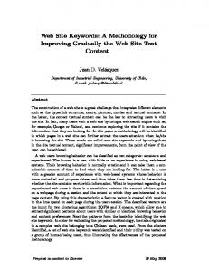
4. Two-tier MVC Architecture for Web Applications
Building on top of the Struts technique, we propose a two-tier MVC architecture for web applications, as shown in Figure 6. We use this architecture as the backbone to design the template files for GG generator to generate a running application. A web application system is divided into two layers, front-end and backend, and each layer is organized into a MVC architecture. The front-end tier includes JSP pages, Servlets and Struts engine, while the back-end tier comprises all EJB engines and database. Comparing to usually called three-tier architecture that is mostly popular as distributed object architecture [37][38], our front-end tier can be considered a normal front-tier, while our back-end tier contains the normal middle-tier and back-
Frontend View
Controller
Model Database
JSP Page form bean
Struts Servlet
Pre-action Service
EJBs
Controller
Model
Post-action
View
Backend
Figure 6. Two-tier MVC architecture
13
end-tier. We adopt this architecture because the most recent middle-tier tools (e.g., EJBs) effectively incorporate the database while hiding the details of database organization from the front-end tier [37]. An entity bean represents persistent storage and session bean represents business logic, and both of them are integrated in EJB framework. Therefore, the use of EJB leads to a simplified architecture in which the middle tier and back-end tier typical of traditional web applications are merged.
In the front-end tier, we formalize the Struts framework as follows. Every JSP page represents a view, together with a form bean that holds the contents for the page. We can see that this relationship also shows a tiny MVC pattern: the JSP is a view, the form bean is the model, and the Struts engine maintains the oneto-one mapping between them acts as the controller. The controller is a servlet that inherits its features from Struts servlet.. Two action classes act as the model. We use a (pre-, post-) action pair to emulate the data flow of web pages. Pre- action prepares the contents for the JSP view, while post- action gathers user input from the JSP page and performs some operations. For every page shown on the web, there is always a JSP page, a form bean, and two actions. The advantage of this formalization is to capture the essential scheme under every web page. We prepare the content for display, and then catch the feedback to change the state of the system. We regulate these two kinds of operations in pre-and post-actions respectively, so the data flow is clear.
Actions act not only as a model of the front-end tier, but also enable a view of the back-end tier. The purpose of the back-end tier is to provide system state information to the front-end. Thus we can consider actions as agents providing different ways to present back-end states to the front-end. We construct a service layer to serve as the controller, which deals with all the business logic. EJB or other data objects act as the model, and hide all database details.
This architecture clearly identifies an object-oriented component-layered structure for a web application. It integrates front-end framework with back-end technology. This model provides a reasonable backbone for web applications, so that we can easily construct a corresponding template system for GG generator to build a running mockup system. According to this architecture, any module in a web application, when
14
decomposed with small enough granularity, can be realized by a composition of JSPs, form beans, servlets, pre- actions, post- actions, service methods, EJB components and database schemas. In other words, if we want to develop a unit function in a system, we could develop the seven categories of code artifacts as discussed above.
5. Supporting Environment (MODFMEnv)
Based on the two-tier MVC architecture, we construct what we refer to as MODFMEnv, a tailored environment to support design and prototyping of web applications. The overall picture is shown in Figure 7.
MODFMEnv is built on top of an application server, which in turn is on top of a database.
MODFMEnv consists of five components: generic code generator (GG), GG editor,
menu system
generator (MSG), framework, and web application template system (WATS).
The framework maintains the relationships between different web pages throughout the menu system. The framework divides every web page into two parts: menu part and content part as a JSP page. The Menu part is fully handled by the menu system as long as it is generated by a menu system generator. It loads the
GG Editor
Menu System Generator
GG Generator
MODFMEnv
Web Application Template System
Framework
Application Server Database Figure 7. MODFM Environment
15
corresponding JSP page according to a user’s choice. This separation provides a loose coupling between different pages. Developers can configure the linkages between pages in an XML file, and update it afterwards.
The framework also provides authentication control, security control, and other utility
functionalities. The framework provides support to both the GG generator and the MSG. The GG editor is a tailored editor that helps users prepare data files and configuration files for code generation; it is the component users directly interact with in this environment.
WATS is a specific application server oriented to support a template system designed to provide a skeleton for sets of files to be generated. The GG generator, combined with this template system, can be used to automatically generate the whole structure of a web system, with the exception of business algorithms. Most of the templates in a template system can be fully reused if another application server is adopted. Generally, only the EJB deployment descriptor template needs to be replaced, conditional on the application server used. The menu system generator is separated to generate a hierarchical menu system,
Form Bean
JSP
Pre-action
Post-action
Java Bean
WebGen Template System
Entity Bean Home Interface
Entity Bean Remote Interface
Entity Bean Impl.
Session Bean Home Interface
Session Bean Remote Interface
Session Bean Impl.
Service Layer Deployment Descriptor Database Schema
Figure 8. WebGen template system
16
and provides an easy way to register web pages to the corresponding menu items. The difference between WATS and other code generators lie in the following aspects. First, WATS is tailored to an underlying software architecture that we described in the previous section. Second, based on the architecture, WATS provides a complete set of template systems to generate a fully functioning running system. Third, a template system is highly reusable on different web application servers.
As illustrated in Figure 8, WATS comprises 14 templates for web applications. Providing code templates from the front-end to the back-end of a web system, these template files (as shown in Figure 3), are applied to data files (as shown in Figure 2), to generate target files. Let us have a more detailed discussion on what files will be generated based on one data file. We make an assumption that every attribute in a data file is shown on screen in a text field, where it can be easily changed to other display widgets later on. Therefore, JSP Template File (TF) helps to generate a JSP page including all fields of the data file, while the form bean TF helps generate a form bean file containing all information for the JSP page. Pre-action and postaction TFs contain templates to generate actions to prepare for and gather information from respective web pages, while the code for data exchange with back-end are left as dummy pieces. Java bean TF contains templates of generating business data objects. The entity bean home interface, remote interface, and implementation TFs contain templates for generating an EJB entity bean. The session bean home interface, remote interface, and implementation TFs contain templates for generating an EJB session bean. The deployment descriptor TF contains templates to generate deployment descriptor pieces for corresponding entity beans and session beans. Service layer TF contains templates to generate service method signatures. Database schema TF contains templates to generate corresponding database SQL queries for creating and deleting tables in the database. Thus, with the template system, a developer merely needs to provide a data model along with some defining criteria and WebGen will generate a running web system.
6. Mockup-driven Fast-prototyping Methodology (MODFM)
On the basis of MODFMEnv, we propose a mockup-driven fast-prototyping methodology (MODFM) for web applications. MODFM comes to play in the web engineering life cycle when a primitive analysis
17
1. 2. 3. 4. 5. 6. 7. 8.
Functional decompose the system to hierarchical menu items. Call menu generator to generate the menu system to client. Design web pages for each menu item, to get a set of pages. Design data model. Call generator system to generate all types of codes. Map pages with menu system to get mockup system to client. Gather user feedback and go back to step 3. to do modifications. Add business logic to service methods, to get a running system. Figure 9. Mockup-driven fast-prototyping methodology
document has already been produced from initial requirements analysis. The procedure is summarized as eight steps in Figure 9. An assumption is that the primary project analysis document is prepared as the starting point of MODFM. In this section we discuss the process in detail. In Figure 10, actions are illustrated as text and arrows annotated with numbers; shapes show the results of actions; ovals show the deliverables submitted to clients. For example, the first action of MODFM is the functional decomposition of a primary project analysis document. The result of this functional decomposition is a set of menu items from which a generated menu system is created and is subsequently submitted to the clients as the first deliverable.
Step 1: is to treat the entire system as one functional module, specify relative scenarios at high level, then use functional decomposition to divide the system into modules and sub-modules, and then organize the modules into hierarchical menu items.
Step 2: is to use the menu generator to generate a hierarchical menu system, which is submitted to the client to review. This will become the first demo for the client. Normally the client will give feedback very quickly, since this decomposition can be usually mapped to the division of functional departments or offices in the real world. This menu system is the first milestone of the project. If some modifications are desired, these are first reflected in a project analysis document, where system requirements are refined. Then the next action is to go back to step 1. The iteration in this loop ensures high-level requirements refinement and revision to a large degree.
18
2.5 requirements refinement
Project Analysis Document
Client
Menu System
1.functional decomposition
2.generate 3.design pages Menu Items
4.design Set of Pages
Data Model 5.generate
7.user feedback
Running System
Ready for testing
8.add businss logic to service methods
6.map with menu system Mockups
JSP Page Form Bean
Service Methods EJBs
PreAction Client
PostAction
Database Schemas
Figure 10. MODFM procedure
Step 3: is to design web pages for each menu item. For some of the menu items, only one page is necessary. For example, if a menu item is to display some results based on the user id, only one page will be designed. For some other menu items, however, there might be several pages associated. For instance, let us consider a scenario behind a menu item: gather input from the user, retrieve information back, let user do some modifications, and then change the system status accordingly. In this example it is reasonable to adopt several continuous pages. As a result, we may get a set of pages at this step.
Step 4: is to design the data models based on the pages specified. In general, these pages provide a good guideline for identifying data models. For example, if a page contains information on a person’s address, an address class might be an appropriate data model. The data model is stored in XML files. It is natural to use any traditional OO methodology to help identify data models here, since this activity is analog to identifying entities in the real world as so called class-oriented decomposition.
19
Step 5: is to utilize code generator GG to generate all codes associated with each identified page. MODFM environment already provides a set of pre-defined web application template files, as illuminated in Figure 8. What a developer needs to do is to prepare a configuration file which links each data model to the group of template files as required. One can also specify additional criteria to the generator, following the discussion in the previous section. Seven main categories of codes are automatically generated: JSP page, form bean, pre- action, post-action, service method skeleton, EJBs including entity beans and session beans, and database schema. Some other utility codes are also be generated, such as codes for Struts mapping, and utility codes for validation error messages.
Step 6: is to map pages to every menu item. This is as simple as registering the corresponding pre- actions of the page to the relative menu item in an XML configuration file.
The menu generator and the
framework package will handle the rest of the work. At this point, we can get a fully functional running mockup system, which has all the user interfaces that will appear in the final system, and is ready to be present to the client. This mockup system is the second demo for the client.
Step 7: is to gather the client’s feedback from the delivered mockup. If changes are required, the procedure goes back to step 3, and this process iterates until the client accepts the mockup. Otherwise, a new milestone is generated, called “approved mockup”, and the procedure goes to Step 8. These iterations can be conducted easily, since all of the code can be regenerated automatically based on the updated data model XML files. For modifications such as rewording edits that are irrelevant to the generated code, change flags can be set to part in the configuration files, which will prevent these modifications from being overwritten. At this stage, every mockup page becomes a use case. Discussion with the clients will finalize the underlying business scenarios, thus in turn will also finalize the data models.
After the mockup is accepted, the only thing left is step 8, to integrate business logic into the corresponding service methods. Portions of code implementing business logic are inserted into the related method body of the generated files. Before the development of this code, analysis documentation and project solution
20
package selections need to be approved by the client, so as to ensure the correctness of the business scenario to be implemented. After this step is finished, a complete system is ready for the testing phase.
7. An Example Application: e-University Suite
Figure 11. Snapshot of the e-University suite
One of the projects where MODFM is actually being used is the design and development of an e-University suite. Figure 11 is a snapshot of the running system. We will describe how we use MODFM to build up a mockup system. Based on functional analysis, we decompose the system into seven modules: student records, admissions, staff, registration, financial aid, financial services, and faculty. Each module can be in turn decomposed into sub-modules, as shown in Figure 12 as a two-layer menu. This menu was the first submission to the client.
21
Student Records
View Transcript Transcript Request View Grades
Admissions Financial Aid FInancial Services Registration
On-line Application
Financial Aid Availability
View Taxpayer Relief Act Information
Financial Aid Application
View 1098-T Form View Account Information
View/Change Address
Staff
View Student Add Class Transcript Drop Class View Student Grades View Student View/Change Schedule Student View Course Address Schedule View Student Taxpayer Relief Academic Act Information Catalog View Student Student 1098-T Form Evaluation View Student Account Information View Student Schedule View Student Evaluation
Faculty
Grade Entry Syllabus
View Syllabus
Figure 12. Menu system of e-University suite
The second step was designing mockup pages for each menu item. Some of the menu items include only one mockup page, such as “View Transcript” item under “Student Records” module, and “Student Evaluation” item under “Registration” module. These pages display the results of some queries. Some other menu items include multiple mockup pages, such as “View/Change Address” item under “Student Records” module. The first page shows the address of the student in a view-only mode. A button allows the student to edit the address. Thus the second page is the student address in edit mode. Another example is “On-line Application” item under “Admissions” module. The application form is usually very long, so it is appropriate to divide the form into several pages according to the related sections.
The third step was designing the data model for each mockup page. Using “View Address” page for instance, the page holds a student’s address information, so it is natural to design an address class as the data model. Normally a page contains one data model that maps to a table in the database. But for some pages, the data model contained is very complicated so it needs to map to several tables in the database. We will give an example of this later.
The fourth step was generating the code. We used each data model to generate JSP page, form bean, preand post- actions, mapping in struts-config.xml, entity bean, deployment descriptor, session bean, service method, and database schema. We summarize this generated work in Figure 13.
22
Figure 13. Piece of configuration file for e-University suite
Let us take a closer look at Figure 13. The first part is the XML definition for data model StudentAddress. GG generator uses keyword Data to verify the section of data model, Name to verify the name of the data model, and TNAME to verify the table to be generated in the database. Inside of the pair of Data tag is the description of the data model. Each attribute is defined in one line, by the definition of name, data type, whether it is unique, and whether it needs validation when inputted.
The second part is the XML definition of criteria for the codes to be generated. We first defined the output root directory and the data model to be used. We defined how to generate every type of file, e.g., each in one line. A template file needs to be provided, an output directory under the root directory is optional, and a change tag is used to define whether the whole file needs to be regenerated or only the specific part will be replaced by regenerated codes. As we discussed before, the generated file name will be decided based on the template file name, and replace the “=OBJ=NAME=” part with the name of the data model.
23
After running the GG generator, we produced the following generated files:
•
mapping for StudentAddress in univ\Jrun\servers\univ\WEB-INF\Struts-config.xml;
•
univ\Jrun\servers\univ\StudentAddress.jsp;
•
univ\app\forms\ StudentAddressForm.java;
•
univ\app\actions\PreStudentAddressAction.java and PostStudentAddressAction.java
•
univ\app\businesObjects\StudentAddress.java
•
univ\app\ejb\entity\StudentAddressEJB.java, StudentAddressEJBHome.java, and StudentAddressEJBImpl.java
•
deployment description part in univ\Jrun\servers\univ\WEB-INF\META-INF\ejb-jar.xml
•
univ\app\ejb\session\StudentAddressSession.java, StudentAddressSessionEJBHome.java, and StudentAddressEJBImpl.java
•
error message pieces in univ\Jrun\servers\univ\WEB-INF\classes\ApplicationResources.properties
•
all method skeletons in univ\app\StudentRecordsService.java
As we mentioned earlier, some pages contain a data model that is complicated enough to break into mapping to several tables in the database. As an example refer to ContactInfo, as shown in Figure 14. Every leaf node maps to a table in the database. The corresponding configuration code for generation is also shown in Figure 14. One might notice that ContactInfo includes StudentAddress. Thus we do not need to repeat the generation configuration piece for StudentAddress, and the same concept is applied to other similar leaf nodes, such as Name, and AddressType. We can see that no entity beans will be generated, nor any table and deployment descriptor pieces. Applying the same method to all data models, we got a running mockup for the project, which was ready for the client to view. After delivering the mockup to the client, the client was satisfied with the contents, with the exception of minor wording edits in the pages. . To perform these changes we simply went to the corresponding JSP pages to make the modification and delivered the updated mockup to the client. After the client agreed with the final mockup, the only work needed was to embed the business logic into the corresponding service layer, that is, to
24
ContactInfo Collection addressUsages Collection additionalContacts EmergencyContact emergencyContact AddressUsage AddressType addressType PersonalContact addressInfo
AddressType String addressCode String addressName boolean viewable boolean updatable boolean datesRequired
AdditionalContact String contactId String contactName String contactNumber
EmergencyContact Name name Address address String phone
PersonalContact Address address String dayPhone String eveningPhone Address Address
Name
Figure 14. Example of configuration for ContactInfo Data Model
replace the dummy method body with the real business scenario. All other code and interfaces required no additional modification.
After the whole application was delivered, the code was examined for analysis. We found that only 9.62% of the final code was eventually coded by developers; while 90.38% of the system was automatically generated. As a result, since over 90% of the code was automatically generated, the code quality was guaranteed, the development process was greatly shortened, and the subsequent test phase shortened. As a matter of fact, the project was originally assigned to a team of four full-time developers with time frame of four months. With the adoption of WebGen, the project was accomplished by one a full-time developer (the first author of this article) together with a part-time JSP designer and programmer. Our initial
25
experience with this system indicates that WebGen can provide improvements in development speed while enhancing the reliability of the resulting applications.
After the project was delivered, the university requested to deploy the system to another environment that required significant changes, ranging from data model to front-end interface modifications. However, the overall business logic and scenarios remained the same.
Since WebGen provides the flexibility to
regenerate portions of a file that relate to corresponding template files, the base system was highly reused. All template files and configuration files remained unchanged, while only data files were modified if as required. Therefore, the developer spent three days with the clients accumulating change requests and completing a new requirements document and then spent only one-day modifying data files so as to reflect change requests. Afterwards, WebGen was invoked again, and a new complete system was constructed. The developer did not manually update any regenerated Java code. The only thing left to do was to ask the visual designer to adjust JSP pages according to the client’s requests. Our empirical experience on this project demonstrates the reusability of our WebGen tool.
There were also issues that arose from our experiment. One of the most important advantages of using MODFM is that our WebGen could automatically generate code from the front-end to the back-end. However, we require that the mappings between the front-end JSP pages and business objects that relate to the back-end system cannot be too complicated.
Therefore, a senior-level architect is required to
decompose and design the object model for big-scale complex systems. Overall, we feel that more WebGen internal facilities should be provided to enhance the ability of MODFM to support large-scale complicated web applications.
8. Conclusions and Future Work
MODFM is an architecture-based methodology that guides developers to quickly construct a prototype of a web application. MODFM applies a top-down approach to functionally decompose a system into web pages organized in menu system, while generating all the code, the from front-end all the way to the back-
26
end, integrating it into a running mockup system.
While analysis efforts are unavoidable in any
development cycle, MODFM reduces this effort by loosely coupling the analysis phase and development phase. The key idea is to construct a mockup system as early stage as possible. A mockup system can often be the best communication media with a client to elicit, validate, and finalize the requirements at the user interface level. Early mockup systems offer clients an opportunity to participate in the design and direction of the system at a very early stage. It facilitates the discussion of analysis phase. It gives a client a real feeling of how the system will look and feel. It also offers clients’ confidence and avoids last minute project re-engineering.
Architecture-based code generation helps to build a running mockup system with minimal development effort. Furthermore, a mockup system can be easily regenerated based on modifications from client feedback. This automatic generation engine offers easy iterative versions of mockup system. Business logic is embedded in methods in the service layer only and all other layers are automatically generated from the template system and data model. Template system can be reused in other web applications using the same technologies. Different applications modify the data model thus get a different mockup system generated. Business logic can also be reused with other methods. MODFMEnv not only provides a fastprototyping environment, but also provides a highly reusable development environment. MODFM can be applied to any size of web application development and it is especially efficient for large and complex web applications.
Even without MODFMEnv, the methodology is still applicable for web design and
development, but MODFMEnv provides powerful code generators to help construct mockup systems easily and quickly.
Our future work will include an Integrated Development Environment (IDE) to support MODFM. Currently, developers need to set up data models and configurations in a set of XML files. Although developers’ programming work has already been decreased significantly, we would like to build a GUI based IDE environment to help developers construct and organize required XML files resulting in even faster generation of a mockup system.
27
Acknowledgements
We would like to acknowledge our appreciation to David Flaxer for proof reading our manuscript.
References
[1] P. Fraternali and P. Paolini, “Model-driven Development of Web Applications: the AutoWeb System”, ACM Transactions on Information Systems (TOIS), Vol. 18, Iss. 4, Oct. 2000, pp. 323-382. [2] I. Sommerville, Software Engineering, Addison-Wesley Pub Co; ISBN: 020139815X; 6th edition. [3] P. Szekely, User Interface Prototyping: Tools and Techniques, USC/Information Sciences Institute, 1994. [4] M. Bochicchio and R. Palano, “Prototyping Web Applications”, Proceedings of the 2000 ACM Symposium on Applied Computing, 2000, Como, Italy, pp. 978-983. [5] The American Heritage Dictionary of the English Language, 4th edition, Houghton Mifflin Company, 2000. [6] A. Ginige and S. Murugesan, “The Essence of Web Engineering – Managing the Diversity and Complexity of Web Application Development”, IEEE Multimedia, Apr. 2001, pp. 22-25. [7] M. Gaedke and J. Rehse, “Supporting Compositional Reuse in Component-Based Web Engineering’, Proceedings of the 2000 ACM Symposium on Applied Computing, Como, Italy, pp. 927-933. [8] E. Gamma, R. Helm, R. Johnson, and J. Vlissides, Design Patterns, Addison Wesley 1994. [9] F. Garzotto, P. Paolini, and D. Schwabe, “HDM – A Model Based Approach to Hypermedia Application Design”, ACM Transactions on Information Systems, Vol. 11, Iss. 1, Jan. 93, pp. 1-26. [10] P.P. Chen, “The Entity-Relationship Model: Toward a Unified View of Data”, ACM TODS, Vol. 1, Iss. 1, 1976, pp. 9-36. [11] J. Conallen, ”Modeling Web application architectures with UML”, Communications of the ACM, Vol. 42, Iss. 10, Oct. 1999, pp. 63-70. [12] T. Isakowitz, A. Stohr, and E. Balasubramanian, “RMM: A Methodology for Structured Hypermedia Design”, Communications of the ACM, Vol. 38, Iss. 8, Aug. 1995, pp. 34-44.
28
[13] M. Gaedke, D. Schempf, and H.W. Gellersen, “WCML: An Enabling Technology for the Reuse in Object-Oriented Web Engineering”, Poster-Session at the 8th International World-Wide Web Conference (WWW8), 1999, Toronto, Ontario, Canada. [14] Y. Lei, E. Motta, and J. Domingue, “IIPS: An Intelligent Information Presentation System”, Proceedings of the 7th International Conference on Intelligent User Interfaces, 2002, San Francisco, CA, USA, pp. 200-201. [15] S. Ceri, P. Fraternali, and A, Bongio, “Web Modeling Language (WebML): A Modeling Language for Designing Web Sites”, the 9th International World Wide Web Conference, Amsterdam, Netherlands, May 2000, pp. 15-19. [16] R. Wieringa, “A Survey of Structured and Object-Oriented Specification Methods and Techniques”, ACM Computing Surveys, Dec. 1998, pp. 459-527. [17] E. Yourdon, Modern Structured Analysis, Yourdon Press, Upper Saddle River, N.J., 1989. [18] G. Booch, I. Jacobson, and J. Rumbaugh, The Unified Modeling Language User Guide, AddisonWesley, Reading, MA, 1998. [19] N. Medvidovic et al., “Modeling software architectures in the Unified Modeling Language”, ACM Transactions on Software Engineering and Methodology (TOSEM), Vol. 11, Iss. 1, Jan. 2002, pp. 2-57. [20] http://java.sun.com/j2ee. [21] http://jakarta.apache.org/struts. [22] http://www.jostraca.org/links.html. [23] Y. Lei, E. Motta and J. Domingue, "An Ontology-Driven Approach to Web Site Genenration and Maintenance", Proceedings of 13th International Conference on Knowledge Engineering and Management, Sigüenza, Spain, October 1-4, 2002, pp. 219-234. [24] http://www.kapitec.com/Produits/CodeCharge/en/codecharge_std.htm. [25] http://www.koolfrog.com. [26] http://www.beust.com/cedric/ejbgen/#introduction. [27] http://www.code-generator.com/. [28] http://industry.java.sun.com/solutions/products/by_product/0,2348,ejb-5791-28,00.html. [29] http://www.imatix.com/html/gslgen/index.htm.
29
[30] http://www.jeewiz.co.uk/index.html. [31] .B. McLaughlin and M. Loukides, “Java and XML”, O’Reilly Java Tools, 2001. [32] J. Sigle, “Structured Development of Menu-Driven Application Systems”, Proceedings of the International conference on APL:part 1, New York, NY, USA, 1979, pp. 188-195. [33] B. Friman, “MGEN – A Generator for Menu Driven Programs”, Proceedings of the 7th International Conference on Software engineering, Orlando, FL, USA, 1984, pp. 198-206. [34] http://java.sun.com/docs/books/tutorial/uiswing/mini/index.html. [35] http://xml.apache.org. [36] http://java.sun.com/j2se/1.4.1/docs/api/index.html. [37] R. Monson-Haefel, Enterprise JavaBeans, O’Reilly & Associates, Inc. ISBN: 0-596-00226-2, 3rd edition, 2001. [38] A. Thomas, “Enterprise JavaBeans Server Component Model for Java”, prepared for Sun Microsystems by Patricia Seybold Group, 1997, http://java.sun.com/products/ejb/white_paper.html.
30