Jul 26, 2009 - ments capable of expressing high-level software architectures as well as low-level, ... dataflow, scheduling, mode grouping. 1. INTRODUCTION .... points into deformation field is through B-spline interpola- tion in three ...
52.3
Mode Grouping for More Effective Generalized Scheduling of Dynamic Dataflow Applications William Plishker, Nimish Sane, and Shuvra S. Bhattacharyya Electrical and Computer Engineering Department and Institute for Advanced Computer Studies University of Maryland College Park, Maryland, USA
{plishker, nsane, ssb}@umd.edu ABSTRACT
languages are increasingly popular. Their diversity, portability, and intuitive appeal have extended them to many application areas with a variety of targets. As system complexity increases in digital signal processing platforms, designers are expressing more types of behavior in dataflow languages. While the semantic range of DSP-oriented dataflow models has expanded to cover dynamic interactions, many of the powerful static optimizations algorithms have become less applicable. This is especially problematic in scheduling, which impacts key implementation metrics for embedded software systems, like memory size, performance, and power consumption (e.g., see [9]). Even though new applications are dynamic, they still exhibit static behavior during execution. This may be in the form of static subsystems or repetitious sequences of actions that occur during otherwise dynamic execution. While current techniques already address the former, the latter is unexploited. Traditional static scheduling techniques are potentially applicable to these application-wide static sequences, but the behavior must be identified and properly modeled based on the original application description. In this paper, we extend a scheduling algorithm [7] that takes a dynamic application described in the functional dataflow interchange format formalism [8] and decomposes it into a set of static dataflow graphs. In particular we introduce a notion of grouping actor modes, which allows certain static sequences of fixed actions to be exposed to a scheduler. This exploits the statically known behavior of an otherwise dynamic actor resulting in a more efficient schedule for the overall application.
For a number of years, dataflow concepts have provided designers of digital signal processing systems with environments capable of expressing high-level software architectures as well as low-level, performance-oriented kernels. To apply these proven techniques to new complex, dynamic applications, we identify repetitive sequences of atomic, repeatable actions (“modes”) inside dynamic actors to expose more of the static nature of the application. In this work, we propose a mode grouping strategy that aids in the decomposition of a dynamic dataflow graph into a set of static dataflow graphs that interact dynamically. Mode grouping enables the discovery of larger static subgraphs improving scheduling results. We show that grouping modes results in improved schedules with lower memory requirements for implementations by up to 37% including a common imaging benchmark with dynamic behavior: 3D B-spline interpolation.
Categories and Subject Descriptors D.4.1 [Operating Systems]: Process Management
General Terms Algorithms, Management
Keywords dataflow, scheduling, mode grouping
1.
INTRODUCTION
Dataflow models have become both an important formal underpinning for tools and a convenient way of reasoning about applications in a precise manner for application areas such as digital signal processing (DSP). Their graphbased formalisms allow natural and yet semantically rigorous application descriptions. Such a semantic foundation enables a variety of analysis tools, including determining buffer bounds and efficient scheduling [6]. As a result, dataflow
2. BACKGROUND 2.1 Dataflow Modeling Modeling DSP applications through coarse-grain dataflow graphs is widespread in the DSP design community, and a variety of dataflow models have been developed for dataflowbased design. A growing set of DSP design tools support such dataflow semantics. Designers are expected to be able to find a match between their application and one of the wellstudied models, including cyclo-static dataflow (CSDF), synchronous dataflow (SDF), single-rate dataflow, homogeneous synchronous dataflow (HSDF), or a more complicated model such as boolean dataflow (BDF). Common to each of these modeling paradigms is the representation of computational behavior as a dataflow graph. A dataflow graph G is an ordered pair (V, E) , where V is a set of vertices (or nodes), and E is a set of directed edges.
Permission to make digital or hard copies of part or all of this work for personal or classroom use is granted without fee provided that copies are not made or distributed for profit or commercial advantage and that copies bear this notice and the full citation on the first page. To copy otherwise, to republish, to post on servers or to redistribute to lists, requires prior specific permission and/or a fee. DAC’09, July 26-31, 2009, San Francisco, California, USA Copyright 2009 ACM 978-1-60558-497-3/09/07....10.00
923
� � � � �� �
��
� �� �
�
�
����� ����
����
� �� �
�� �� �����
�
�����
�
� �
� �
� �����
�
� ����� �
�
�
�
� ����� �
�
�
� ��� ��� ���
������ ���
������� ���
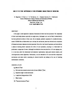
Figure 2: Mode decomposition of switch application
�������� � �
� �� � � �
��
� �
mode Control True False
namic dataflow graph into a set of static subgraphs [7]. To construct a single static subgraph, it finds the combination of modes in which one mode from each actor in the subgraph is producing or consuming on an edge that has a consuming or producing mode respectively at the other end of the edge. For example, consider the decomposition that results from Figure 1 as shown in Figure 2. From these static subgraphs, generalized schedule trees (GSTs) are produced [5]. A GST is a schedule representation based on ordered trees where leaf nodes represent the actors of a dataflow graph and internal nodes represent loop counts.
����
� �
consumes Control Data 1 0 0 1 0 1
produces True False 0 0 1 0 0 1
Figure 1: Boolean dataflow Switch in CFDF.
2.4 Related Dynamic Dataflow Work Besides CFDF, there are a variety of other dataflow models and dataflow based design environments that capture and simulate dynamic applications. In the Stream Based Function (SBF) model of computation [4], actors are represented by a set of functions, a controller, state, and transition function. Ptolemy II encompasses a diversity of datafloworiented and other kinds of models of computation [2]. Developers employ a “director” that controls the communication and execution schedule of an application graph. Beyond modeling, dataflow has been used in the optimization of dynamic systems. For example, systems with data dependent communication can be modeled with variable rate dataflow [10]. When dynamic behavior is modeled as such, buffer capacities can be computed based on throughput constraints in the application. By contrast, our work focuses on identifying more static behavior in a dynamic application so that traditional scheduling techniques can be used. While Functional DIF is used as our demonstration vehicle for extending generalized scheduling, the techniques and results should be applicable across many such tools.
A directed edge e = (v1 , v2 ) ∈ E is an ordered pair of a source vertex v1 ∈ V and a sink vertex v2 ∈ V . Nodes or actors represent computation while edges represents a FIFO communication links between them. One of the semantic foundations for a structured dynamic dataflow formalism is core functional dataflow (CFDF) [8], which is capable of expressing deterministic, dynamic dataflow applications. In this formalism, each actor a ∈ V has a set of modes, Ma , in which it can execute. Each mode, when executed, consumes and produces a fixed number of tokens. For example, consider the Switch actor and four SDF actors in Figure 1 with the mode behavior of the Switch actor shown below it.
2.2 Dataflow Interchange Format To describe dataflow applications for the wide range of dataflow modeling techniques that are relevant to DSP system design, application developers can use the dataflow interchange format (DIF) [3], a standard approach founded in dataflow semantics and tailored for DSP system design. It provides an integrated set of syntactic and semantic features that can fully capture essential modeling information of DSP applications without over-specification. DIF is designed to describe mixed-grain graph topologies and hierarchies as well as to specify dataflow-related and actor-specific information. The DIF package transforms DIF descriptions into an internal representation and contains graph utilities, optimization engines, and other utilities. Functional DIF also supports CFDF making it an effective environment for modeling dataflow applications, providing interoperability with other design environments, and developing new tools.
3. MODE GROUPING While static subgraphs can be successfully found by a generalized scheduling approach to dynamic applications [7], some static behaviors are not considered. For example, in the decomposition of our switch application from Figure 2 the True and False modes act predictably, always returning to Control, which is the mode that transitioned to them in the first place. The repeatable nature of these branches are the kind of static behavior that is exploitable but is not found by existing generalized scheduling approaches. To this end, we augment our actor description with the concept of mode grouping, in which application writers can refine their original application by grouping modes together. For an actor a with modes Ma , we define a mode grouping, Da ⊆ Ma as a set of modes with a static relationship. The static mode behavior we expose in this work is cyclic mode transitions in which all modes in the grouping return exactly one mode as the next mode, except for one mode, called the
2.3 Generalized Scheduling While there exist techniques for finding static islands in a dynamic application, more static behavior can be found in dataflow graphs described in CFDF. A generalized scheduling approach can utilize the fact that every mode has fixed production and consumption behavior and decompose a dy-
924
SRC
Table 1: The actors in the cubic B-spline application (“control” corresponds to c* edges and “point” corresponds to d* edges) consumed prod Actors Modes control point data out Grid Normal NA 3 NA 192 Lookup Control 1 0 0 0 Interp New Cube 0 1 192 48 Plane Recalc 0 1 0 48 Control 1 0 0 0 Interp New Plane 0 1 48 12 Row Recalc 0 1 0 12 Control 1 0 0 0 Interp New Row 0 1 12 3 Point Recalc 0 1 0 3 Print Normal NA NA 3 NA
coord CONTROL coord GRIDLOOKUP
cz
dz
data
cy dy
INTERP_PLANE
cz
dx
data INTERP_ROW data INTERP_POINT data PRINT
Figure 3: Dataflow graph of 3D cubic B-spline entrance mode. The entrance mode may have multiple transitions out, as it marks the single point of dynamic behavior in the grouping, but after it is fired, the modes that follow it do so in a static sequence. The mode grouping can be considered by the scheduler as a single mode that has production and consumption behavior equal to the sum of the individual modes in it. The resulting schedule then includes a repeated firing the size of the mode grouping. In our switch example, two mode groupings are Da = {{control, true}, {control, f alse}}, each with Control as the entrance mode. This exposes that Control always precedes a True or a False, allowing a larger schedule tree to be formed. For this small example performance benefits are slight, but for more complex applications, the assertion that a set of modes execute in a static sequence can lead to notably smaller buffer requirements.
4.
Table 2: The CONTROL cons Modes coord coord Control 3 0 New Cube 0 3 New Plane 0 0 New Row 0 0 New Point 0 0
actor modes in B-spline produces cz dz cy dy cx dx 0 0 0 0 0 0 1 1 1 1 1 1 1 1 1 1 1 1 0 0 1 1 1 1 0 0 0 0 1 1
5. RESULTS To evaluate the benefits of mode grouping, we started with a set of both static and dynamic applications with actors that had mode groupings to exploit: the B-spline application presented in the previous section, a CSDF data distribution of audio streams to be sample-rate-converted, a polyphase decimated DFT filter bank, and an application with multiple polynomial evaluation accelerators (PEAs). For each, we ran the generalized scheduler (using APGAN as the static scheduler [1]) with and without mode groupings that were manually added. The resulting schedule trees were balanced and ordered based on the known input conditions, be it static patterns or probability distributions. In the case of the B-spline application, the steps through the different dimensions were known at run-time, and schedule trees were balanced accordingly. Figure 4 shows these five unique schedule trees (each of which has a root at the second level of the tree) that were replicated and ordered with a modified iteration count to account for the number of voxels to be processed at each step. Also for the B-spline application, a valid schedule could not be found by our generalized scheduler without groups. Instead, we generated the flat schedule balanced with equivalent execution rates as shown in Figure 5. We pushed hundreds of input data tokens through each of these implementations to monitor the amount of buffering consumed by the application with that schedule as shown in Table 3. The two purely static applications showed no benefit of using mode grouping. While mode groups were identified in CSDF actors, the original generalized scheduler performed equally well with and without groups. Once any
CUBIC B-SPLINE INTERPOLATION
Splines are commonly used in image processing for applying smooth, non-linear transformation to images. Such deformation fields may be modeled by piecewise polynomial interpolation from basis functions based on a set of control points. They can be computationally efficient by restricting the impact of a control point to a local region, but still be globally smooth. In this work we focus on cubic B-splines which use third order polynomials as their basis functions and use contributions from four neighboring control points. A popular way of transforming a 3-dimensional set of control points into deformation field is through B-spline interpolation in three different axes, each time adding the contributions from two control points before and two control points after the voxel in question. A dataflow implementation of this application (shown in Figure 3) avoids re-computation and additional memory access to the intermediate results of interpolation. Mode behaviors are described in Table 1 and Table 2. Each interpolating actor may accept new inputs for its interpolation step or it may compute another voxel on the shared support of the control points at that step. We exploit grouping in this application by pairing each Recalc and New Cube/Plane/Row mode with the Control mode, creating a total of 6 new modes to the datapath actors.
925
1
16
3
SRC
1
1
CONTROL
CONTROL
1
3
1
GRIDLOOKUP
2
1
1
INTERP_PLANE
CONTROL
3
2
INTERP_POINT
PRINT
INTERP_ROW
1
3
CONTROL
PRINT
1
INTERP_ROW
3
2
3
CONTROL
1
PRINT
2
INTERP_POINT
INTERP_POINT
1
3
CONTROL
PRINT
INTERP_PLANE
1
1
3
2
1
INTERP_ROW
3
CONTROL
PRINT
1
2
INTERP_POINT
1
3
CONTROL
PRINT
1
INTERP_ROW
3
2
1
3
PRINT
CONTROL
2
INTERP_POINT
3
PRINT
INTERP_POINT
INTERP_POINT
INTERP_POINT
Figure 4: Schedule derived from mode grouping for B-spline application [2] J. Eker, J. Janneck, E. A. Lee, J. Liu, X. Liu, J. Ludvig, S. Neuendorffer, S. R. Sachs, and Y. Xiong. Taming heterogeneity - the Ptolemy approach. Proceedings of the IEEE, Special Issue on Modeling and Design of Embedded Software, 91(1):127–144, January 2003. [3] C. Hsu, I. Corretjer, M. Ko., W. Plishker, and S. S. Bhattacharyya. Dataflow interchange format: Language reference for DIF language version 1.0, ˇ guide for DIF package version 1.0. Technical userSs Report UMIACS-TR-2007-32, Institute for Advanced Computer Studies, University of Maryland at College Park, June 2007. Also Computer Science Technical Report CS-TR-4871. [4] B. Kienhuis and E. F. Deprettere. Modeling stream-based applications using the SBF model of computation. In Proceedings of the IEEE Workshop on Signal Processing Systems, pages 385–394, September 2001. [5] M. Ko, C. Zissulescu, S. Puthenpurayil, S. S. Bhattacharyya, B. Kienhuis, and E. Deprettere. Parameterized looped schedules for compact representation of execution sequences. In Proceedings of the International Conference on Application Specific Systems, Architectures, and Processors, pages 223–230, Steamboat Springs, Colorado, September 2006. [6] E. A. Lee and D. G. Messerschmitt. Static scheduling of synchronous dataflow programs for digital signal processing. IEEE Transactions on Computers, February 1987. [7] W. Plishker, N. Sane, and S. S. Bhattacharyya. A generalized scheduling approach for dynamic dataflow applications. In Proceedings of the Design, Automation and Test in Europe Conference and Exhibition, Nice, France, April 2009. 6 pages in electronic proceedings. [8] W. Plishker, N. Sane, M. Kiemb, K. Anand, and S. S. Bhattacharyya. Functional DIF for rapid prototyping. In Proceedings of the International Symposium on Rapid System Prototyping, pages 17–23, Monterey, California, June 2008. [9] S. Sriram and S. S. Bhattacharyya. Embedded Multiprocessors: Scheduling and Synchronization. Marcel Dekker, Inc., 2000. [10] M. H. Wiggers, M. J. G. Bekooij, and G. J. M. Smit. Computation of buffer capacities for throughput constrained and data dependent inter-task communication. In DATE ’08: Proceedings of the conference on Design, automation and test in Europe, pages 640–645, New York, NY, USA, 2008. ACM.
1
48
SRC
32
CONTROL
1
GRIDLOOKUP
4
INTERP_PLANE
8
32
INTERP_ROW
48
INTERP_POINT
PRINT
Figure 5: Rate balanced schedule for B-spline Table 3: Total buffer size requirements with and without mode grouping Without With Percentage Application Groups Groups Improvement BSpline Interp 479 304 37% Sample Rate Conv 2,278 2,278 0% PolyPhase 24 24 0% Multi-PEA 3,802 2,976 22% dynamic behavior was inserted (i.e. the B-spline controller and the PEA dynamic switch and select pair), mode grouping showed a significant improvement finding more (and larger) static schedule trees, which provided a direct savings in buffering by more optimal actor firings. Generalized scheduling with and without groups for each of these examples took less than 5 seconds on a modern CPU.
6.
CONCLUSIONS
The rise of complex, dynamic applications has hindered the applicability of traditional static dataflow analysis. In this paper, we have reclaimed some of this ground by presenting a new extension to a generalized scheduling approach that exposes more static behavior of a dynamic application graph. By identifying static groups of “modes” inside actors, we expose more of the static nature of the application, allowing traditional scheduling techniques to improve on memory requirements by up to 37%. We plan to extend this work by developing dynamic schedule tree selector so that a simulator or a final implementation may strategically switch between the known static behaviors at run-time.
Acknowledgments This research was sponsored in part by the U.S. National Science Foundation (Grant number 0325119), and the US Army Research Office (Contract number TCN07108, administered through Battelle-Scientific Services Program).
7.
REFERENCES
[1] S. S. Bhattacharyya, P. K. Murthy, and E. A. Lee. Software Synthesis from Dataflow Graphs. Kluwer Academic Publishers, 1996.
926