Model-Based Engineering for Database System Development Bernhard Thalheim Christian Albrechts University Kiel, Department of Computer Science Olshausenstr. 40, D-24098 Kiel, Germany
[email protected] Dedication and tribute to Antoni Oliv´e
Abstract. A model functions in a utilisation scenario as an instrument. It is well-formed, adequate and dependable. It represents or deputes origins. This conception of the the model is a very general one. Computer engineering uses models for description of development intentions and for prescription of the system to be build. It typically uses a number of models depending on the layer of abstraction, the scope, the context, the community of practice, and the artefacts to be represented. Model-based development is one of key success factors for development of database systems. This paper thus develops foundations for model-based engineering. Database system development is used as the illustration example for this investigation.
1
Models in Computer Science and Computer Engineering
Models are a kernel element of Computer Science and Computer Engineering (CS&CE). They are used sometimes without any definition or with an intuitive understanding. We know, however, a large variety of model notions (e.g. the 46 notions in [46]). A general theory, technology, art, science, and culture of modelling remain to be one of the research lacunas. 1.1
The Model
A model is a well-formed, adequate, and dependable instrument that represents origins. [11, 44, 45] Its criteria of well-formedness, adequacy, and dependability must be commonly accepted by its community of practice within some context and correspond to the functions that a model fulfills in utilisation scenarios. The model should be well-formed according to some well-formedness criterion. As an instrument or more specifically an artifact a model comes with its background , e.g. paradigms, assumptions, postulates, language, thought community, etc. The background its often given only in an implicit form.
1.2
Multi-Model Modelling
Most sciences use coexisting models as a coherent holistic representation of their understanding, their perception, and their theories. For instance, medical research [8] typically considers medical models as experimentum, practicale, ratio, speculativum, and theoreticalis. These models are developed with different scale, precision, variability, vision, veracity, views, viewpoints, volume, and variation. Each of the models has some functions in utilisation scenarios, for instance, communication, negotiation, construction, and representation and depiction functions. Depending on these functions, the model may be considered to be adequate and dependable. If we use several models then coherence of these models becomes an issue. We may explicitly represent coherence of models through model suites [7, 43]. We may also layer models based on their abstraction and scale, e.g. [17]. UML [32] uses ensembles of models that are loosely coupled. A model suite consists of a set of models, an explicit association or collaboration schema among the models, controllers that maintain consistency or coherence of the model suite, application schemata for explicit maintenance and evolution of the model suite, and tracers for the establishment of the coherence. A specific model suite is used for co-design of information systems that is based on models for structuring, for functionality, for interactivity, and for distribution [39]. This model suite uses the structure model as the lead model for functionality specification. Views are based on both models. They are one kernel element for interactivity specification. Distribution models are additionally based on collaboration models, e.g. [38]. A specific model suite consists of two models which share most of their background, context, community of practice, their application scenario, and thus also function within these scenarios. These models coexist together, are interdependent, and are correlated to each other. We call such models co-model. Co-models form a diptyph1 . They can be coalesced into one model with two different sub-models or they may depend from each other (see, for instance, the K¨onigsberg bridge models in [28] with the topographical, topological and graph-theoretic models). Origins are often also models and thus form together with their model a co-model. The orgin M1 thus conditions its model M2 , i.e. M2 /M1 is a conditional. Modern CS&CE is full of examples of such co-models, e.g. [2, 9, 10, 13, 16, 25, 26, 31, 32, 34, 36, 41]. A model in a co-model also often inherits adequacy and dependability of the other model. Sometimes, they follow however also different backgrounds. For instance, eER-based conceptual modelling uses a global-as-design paradigm. BPMN-based conceptual models are based on a local-as-design approach with an orientation of actors with their roles. 1
A diptych is work made of of two parts. So, we might call co-models also di-models or diptych models.
1.3
Science and Engineering
Science and engineering are two rather different activities. According to the Encyclopedia Britannica [35], science is (1) the state of knowing, (2a) a department of systematized knowledge as an object of study, (2b) something (as a sport or technique) that may be studied or learned like systematized knowledge, (3a) knowledge or a system of knowledge covering general truths or the operation of general laws especially as obtained and tested through scientific method, (3b) such knowledge or such a system of knowledge concerned with the physical world and its phenomena alike in natural sciences, and (4) a system or method reconciling practical ends with scientific laws. Engineering is nowadays performed in a systematic and well-understood form [1]. It also well supported in software engineering, e.g. CMM or SPICE [18]. Engineering is the art of building with completely different success criteria (see [37]: “Scientists look at things that are and ask ‘why’; engineers dream of things that never were and ask ‘why not’.” (Theodore von Karman) “Engineers use materials, whose properties they do not properly understand, to form them into shapes, whose geometries they cannot properly analyse, to resist forces they cannot properly assess, in such a way that the public at large has no reason to suspect the extent of their ignorance.” (John Ure 1998)). S. Oudrhiri [33] considers four elements of matured engineering: “(a) the technological know-how, (b) a set of established practices, (c) a scientific approach for defining the underlying principles of these practices, and ( d) an economical model to explain the implications of such practices in terms of value delivered (effectiveness) and resources consumed (efficiency)”. Engineering is inherently concerned with failures of construction, with incompleteness both in specification and in coverage of the application domain, with compromises for all quality dimensions, and with problems of technologies currently at hand. [48] distinguishes eight stages of engineering: inquire, investigate, vision, analyse, qualify, plan, apply, and report. 1.4
Co-Models and Model Suites in CS&CE
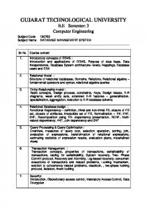
CS&CE often uses direct associations of models, i.e. a model is based on another model. Modelling is then concerned with two models at the same time. For instance, completed database structure modelling starts with a situation model that is represented by a perception model. This perception model is the basis for the business model which is again the basis for the conceptual model. The conceptual model is mapped to a logical model according to the platform for realisation of the database system. The logical model is then mapped to the physical model. This pairwise modelling is based on a dichotomy of the models. This dichotomy is used for closing the gap between the user world (where the information system is a social system) and the IT world (where the information system is a technical system). Figure 1 displays the mediating functions of typical information system models. Classical development methodologies are often based on consideration of two models. For instance, structure modelling might
Fig. 1. Model suites: The five main models that comprise a complete model of a database system
start with a business data model that is intentionally based on the perception model within the user world. This business data model is refined to a conceptual structure model in a conceptual modelling language such as ER [42]. The conceptual structure model is enhanced, transformed or compiled to a logical data model. If we follow a systematic approach then the logical data model is refined, enhanced and transformed to a physical data model. 1.5
Model-Based Engineering as Specific Model-Based Reasoning
Model-based reasoning is reasoning with the aid of models, reasoning about models in their own right, and reasoning that is model-determined [27, 30]. Models have then three different functions depending on these reasoning scenarios [6, 46]: models are instruments for reasoning which implies their prior construction and the reasoning necessary for their construction; models as targets of reasoning; models as a unique subject of reasoning and its preliminary. Abduction has been considered the main vehicle of model-based reasoning. In CS&CE, reasoning is also based on explicit consideration of adequacy and dependability of models within the description/prescription scenario. From one side, models are used as a representation of some thought or better some mental models (e.g. perception models) which are representing the (augmented) reality (i.e. the perceived situation model and the objectives for system construction). From the other side models are used as blueprints for realisation of intentions by software systems. In the last case, models are also documentation models for the software system, at least at the first completion of the system.
Model-based engineering has been considered for a long time as ‘greenfield ’ development starting from scratch with a new development. Engineering is however nowadays often starting with legacy systems that must be modernised, extended, tuned, improved etc. This kind of ‘brownfield ’ development may be based on models for the legacy systems and migration strategies [22]. Again, we observe a co-model approach with a legacy model for revision, redevelopment, modernisation and migration and a target model for development of the new modernised and extended system. So, the legacy model (or legacy models) is associated with a sub-model of the target system.
1.6
The Objectives of the Paper
Model-based engineering attracts a lot of research, e.g. [3, 21, 23, 40]. Modeldriven software development (MDSD) distinguishes enterprise, platform independent, platform specific, and code models. MDSD on the basis of model suites and with a direct consideration of model properties has not yet been investigated. So, we start with a case study in Section 2. This case study is used for derivation of principles in Section 4. Finally, Section 5 discusses the role of conceptual models in model-based engineering of database system development. Due to space limitations, the paper cannot discuss in detail techniques that are necessary for systematic model-based engineering. Many techniques are already developed for specific modelling languages, for specific application domains, and for specific development approaches. A systematic generalisation and harmonisation of these techniques is still a research task. We illustrate the approach based on entity-relationship modelling (ERM) languages, on dataintensive applications and ERM-based development. The paper aims thus in a methodological background for model-based engineering. We restrict the paper to co-models and their specific style for model-based engineering.
2
A Case Study for Structure-Representing Co-Models
Let us consider two cases of co-models. It is often claimed that the ER modelling language can be used at the business and the conceptual layer in a similar form. If we look a bit more into the details then we discover essential differences that must be taken into consideration. For instance, we might have models that cannot be mapped to models at the lower layer or models that cannot be represented at the higher layer. At the same time, we might have many choices for lower layer models (Figure 2). Moreover, data models at one layer might not be entirely represented by data models at the other layer. For instance, cardinality constraints might not be representable by classical relational constraints. We must either enhance the relational language or represent constraints by procedural features of the relational database platforms.
•
•
•
•
Conceptual data models •
•
•
•
Logical data models
•
•
•
•
•
•
Physical data models
•
•
•
•
Business data models
•
•
•
•
•
•
Fig. 2. Association of models in multi-layer modelling
2.1
Co-Models: Business Data Models and Conceptual Models
Business data models reflect the way how business users consider their data. Each business user considers only specific data within a specific viewpoint. A business application provides some kind of collaboration or exchange mechanism for these data. The origins that are reflected in business data models are the situation model of a given application area and a collection of perception models that reflect specific viewpoints of business users. The understanding of data by business users is based on the way of work at business. So, data models represent their rather specific understanding of the application domain. These data models follow a local-as-design representation style. Conceptual models follow however a globalas-design approach [47], i.e. the model consists (i) of a global schema that harmonises and integrates the variety of viewpoints and (ii) of generalised (external) views that are derivable from the form the global schema and represent the local viewpoints. The two kinds of models - the business data models and the conceptual model - are tightly associated by an explicit infomorphism (i.e. generalised di-homomorphisms, see below). Adequateness and dependability of the conceptual model is derived from this association. Additionally, well-formedness of the conceptual model is based on the language, e.g. an extended entity-relationship (eER) modelling language, e.g. HERM [42]. Business (layer) data models and conceptual (layer) data models are a typical example of a vertical model suite since the first one is typically more abstract and the second one can be considered to be a refinement of the first one. The binding among these models is often implicit. We may however enhance the two models by a mapping that maps the first model to the second one. This mapping combines and harmonises the different views that are used at the business user layer. 2.2
Co-Models: Conceptual Models and Logical Models
Logical models are based on the same underlying semantics for the modelling language, e.g. set semantics. Physical data models typically use multi-set semantics (also called bag semantics) for (object-)relational database management systems. Logical models may follow object-relational approaches or purely relational approaches. eER conceptual models have an implicit semantics beside the explicit semantics. For instance, relationship types obey an inclusion and an
existence constraint that restricts existence of relationship objects by existence of their referred component objects – in most cases entity objects. Conceptual views are represented by a collection of object-relational views. We have a number of potential associations between conceptual and logical models. Which one is appropriate depends on choices for structuring, for reorganisation or optimisation or normalisation, for treatment of constraints, for handling of missing values, for controlled redundancy, for treatment of hierarchies, for naming, etc. Additionally, specific platform-oriented features are integrated into the logical model. The transformation follows rules and uses specific decisions. So, the conceptual and the logical models are co-models that follow a refinement approach [49] (1) by injecting specific styles, tactics, embeddings, and language pattern to the logical model [1] and (2) by rules for transformation, extension, enhancement, and specialisation applicable to the logical model [12]. So, a conceptual model is typically associated to many logical models depending on the style of chosen refinement. We may consider an abstract description of the refinement approach as pragmas which are already given together with the conceptual model. The refinement may also result in an information loss. For instance, the view schemata defined for the conceptual model are mapped to a collection of relational views. The interrelation among the relational views is however not maintained in an explicit form. Conceptual (layer) data models and logical (layer) data models also an example of a vertical model suite with a straightforward mapping from the conceptual layer to the logical layer. 2.3
Co-Models: Conceptual Co-Design of Structuring and Functionality
Database design and development typically is based on two models for structuring and functionality. The structure model is the ‘lead’ model for functionality since it defines the signature of the basic terms. The structure model imposes however also restrictions to the functions due to the integrity constraint enforcement and maintenance. Functionality is specified as a set of create-retrieveupdate-delete functions. The data modification functions can be extended for preservation of integrity. The retrieval functions are defined based on a number of retrieval pattern and as algebraic expressions, e.g. HERM+ [42]. So, the lead model is some kind of ‘order’ model and the functionality model is partially ‘enslaved’ [15]. Structure models and functionality models form a horizontal model suite. Their association is based on an infomaorphism (see the similar vertical case in Section 4.1). All elements of the models are associated in a bipartite graph. The edges in the graph may be enhanced by existence dependencies, e.g. an operation or query uses the structural notions which are defined in the structural model. The control of such dependencies may be defined in a form similar to referential integrity.
2.4
Lessons Learned for Model-Based Engineering
A modelling language has its own obstinacy. It injects its background, its limitations and its treatment of semiotics into the model. Therefore, model-based engineering must explicitly represent these language specifics. Whenever models are used within a model suite, the association of models is language-biased and language-limited. Next, models are also driven by the directives, i.e. the artifacts to be represented, the profile of the model that is intended, the community of practice that might accept the model, and the context into which the model is set. Furthermore, the capacity and potential of the model itself restricts applicability. From the other side, we may restrict engineering to some kind of ‘best’ effective and efficient model. Finally, the classical approach to arbitrarily enhance a lower layer model limits the usefulness of the higher-layer model. We may now consider either co-models at the same layer of abstraction (“horizontal co-models”) or at different layers of abstraction (“vertical co-models”). Database structure development is typically based both on vertical co-models that are on adjoining layers and on horizontal co-models in the co-design case.
Fig. 3. Utilisation scenarios for models and stages of their deployment
3
The First Principle of Modelling
3.1
Logoi of Modelling
Modelling results in a model as a surface structure and is in reality combined with a deep structure that is based on the background and the directives of the model. The deep structure of a model is represented by the modelling logos 2 [5, 24] that is the rationale or first principle behind modelling. The model has its background B consisting of an undisputable grounding from one side (paradigms, postulates, restrictions, theories, culture, foundations, conventions, authorities) and of a disputable and adjustable basis from other side (assumptions, concepts, practices, language as carrier, thought community and thought style, methodology, pattern, routines, commonsense) which represent the nature of things themselves. The background provides the deep structure of the model by explanations, analysis and manifestation. It is governed by its inner directives (origins/artefact to represented O, profile of the models (goal, purpose, function)) P and the outer directives (community of practice, and the context) D. It is based on a language L with its general notion, capacity and potential. Model development is based on actions A and modelling and utilisation methods with their rational choice, i.e. the rationality expressed in the model as code, in interpretation and in action. The modelling logos 3 consists of the background, the outer directives, the language, and actions. The modelling logos is expected to understand before model development and utilisation. The logos thus determines the modelling notions of trueness, verifiability, rationality, and correctness. Parameters for models themselves are the inner directives. We claim that models cannot be understood without understanding the modelling logos. 3.2
Scenarios and Resulting Functions of Models
These different meanings of the Greek word logos are used in different utilisation scenarios. Concept and conceptions are the basis for the perception and utilisation scenario. A conceptual model is a model that incorporates concepts and conceptions. Models might be accepted in a community of practice based on judgements of members of a community of practice [19]. Models may be acceptable for this community and be thus intellectually absorbed. Models then gain an expressive power and make sense within an application. Models can also be used and applied in a development process. This application may also use methods of matured development. The last one is based on model-based reasoning which can be guided by maturity approaches, e.g. CMM and SPICE. So, we observe a number of scenarios which are depicted in Figure 3. 2
3
In the Faust poem by J.W. Goethe, Faust reasons in the study room scene on the meaning of the word ‘logos’ λ´ oγoς. This word has at least 6 meanings where Faust used only four of them: word, concept, judgement, mind, power, deed, and reason. The logos combines specification of the language, the knowledge behind, the reality under consideration, and the actions. [24]
Models function as instruments in these scenarios at various stages of maturity. For instance, the application scenario may use models as an inspiration for further development. This stage is often observed for UML-backed programming. Instead, models may be deliberately applied or managed. They may be used as co-models and thus co-evolve together with the realisation, i.e. they become reorganised during utilisation. This reorganisation may also based on systematic approaches and thus be based on a refinement strategy.
4 4.1
Engineering for Vertical Co-Models Database Development with Vertical Co-Models
Vertical co-models are widely used in CS&CE. The methodologies developed so far do however not consider the nature of multi-models. The case studies in Section 2 showed the influence of the background-ladeness of models. It is not easy to switch from a local-as-design paradigm to a global-as-design paradigms. Models are also directives-laden, especially with the outer directives communityof-practice and context. It is simpler if data are of the same granularity, scale and scope. For this reason conceptual models use an approach to represent data at their lowest scale and smallest granularity. Scientific databases (and also industrial databases, e.g. [20]) often start with raw data and consider them as the basis of all derived, purged, combined, and analysed data. They fail whenever size of databases matters. The association between co-models can be based on the notion of the infomorphism. We extend the notion in [22] for models as follows. Two models M1 , M2 are E1 , E2 -infomorph though two transformations E1 , E2 with E1 (M1 ) = M2 and E2 (M2 ) = M1 if any model object o defined on Mi can be mapped via Ei to objects defined on Mj for i, j ∈ {1, 2}, i ̸= j. We notice that this notion allows to associate models with different granularity, models that incorporate views defined on top of a global schema, model suites within the local-as-design style that have a latent association model underneath, and co-evolution of models within a model suite. It can also be extended to model refinement similarly to [49]. We may use the infomorphism also for justification of one model by another model similar to the associations discussed in Subsections 2.1 and 2.2. 4.2
Model-Based Engineering with Co-Models
Model-based engineering is turning an idea into a reality on the basis of models. Models are used as the tacit knowledge for engineering through conception, feasibility, design, manufacture and construction. They reduce complexity while at the same time providing means for sustainable development and for coping with the interdependencies between systems - technical ones as well as social ones, at different layers at the same time. Engineering of information systems still needs a lot of research, theories, skills and practices. System development becomes nowadays based on iterative
development. The time of one-way models is over. Models are becoming reused, reconfigured, continuously evolving and integrated. So, the five plus two models in Figure 1 must co-evolve. Modern CS& CE is not anymore concentrated on a singleton development but has to look outwards, to handle the ‘big picture’, to think and to reflect during practising, to manage complexity and risks at the same time in an economic form. The details of sub-systems are beyond common sense. We must rely on instruments as an abstract source of understanding and managing. One central instrument are models for the system world, for a system, for sub-systems, for embedded systems, and for collaboration of systems. Models allow us to understand what we want, what we think to know and to manage, how we make achieve what we want, what actually to do, and finally what we think might be the consequences. Since engineering is also a business activity, engineering activities must be affordable and financially predictable. Models provide a practical commonsense view that helps us to manage professionally and at acceptable risks. So, model-based engineering is one of the main issues of modern CS&CE. It goes far beyond model-driven development and model-driven architectures. Therefore, we need first-class models and a technology to handle models in a holistic manner. One approach to master development is layering, i.e. coherently deploying various models of social systems and various models for technical systems. We develop this approach on the basis of business/conceptual and conceptual/logical co-models. In a similar form co-design of structuring and functionality may be managed and mastered. So far we considered the modelling logo as a description logo. We may also consider the other model suite logos such as control, application, organisation, economics, and evolution logos for controllers, application, and tracers within model suites. Let us now sketch the controller and application ingredients for model-based engineering with co-models. The model suite association style is based on general schemata for supporting programs (sub-model pattern for release, sharing, and access including scheduling of access), style of association (peer-to-peer , component, push-event, etc.), and on coordination activities describing the interplay among models. The control might be based on lazy or eager control styles. The association pattern among models can be based on wrapping, componentisation, interception, extension or model models. The application processing can be active, proactive, synchronising or obligation-oriented. Synchronisation may use a variety of pattern. Whether association is based on parallel execution depends on the style of the association. The model suite architecture describes inner association among models or submodels and is given by a general network with pairwise or n-ary bindings among these models. The model suite exchange is based on constraints, their enforcement and the handling mechanisms for associations among models and sub-models. They might include also obligations for maintenance of changes within a model suite. The main issue behind this approach is to deeply understand how these models
can coexist, co-evolve, influence and restrict each other, and support or hinder the other. So, we first develop an insight into the deployment and especially the modelling logo of such model suites for a co-model example.
5
Conceptual Models as Mediators Within a Model Suite
The conceptual model is often used as a medium and mediator [29]. “Models function not just as a means but also as a means of representation” [14] with a deep background such as starting points and questions, knowledge, theories, actual hypotheses, tacit knowledge in tools, goals and objectives, tools, data generation, data on hand, data processing, and data interpretation [4]. Mediating models are retrospective and prospective at the same time and ravish. Beside mediation, other and different models can also be developed for documentation, communication, negotiation, orientation, inspiration, etc. 5.1
The Dichotomy of Description and Prescription for eER Models
The main function of eER models is its utilisation during database structure construction. The model consists of a schema, a number of views, and the realisation style [39, 47]. It is descriptive and prescriptive. The descriptive part reflects the business user models and thus uses an explicit association by views. The prescriptive part can be based on realisation templates. Adequacy is given due to the association to the business models, due to the objectives of description and prescription, due to the explicit restriction to the model focus, and due to the realisation context. Dependability is based on the association to the business user model, on the objectives of co-design, and on the capacity and potential of logical modelling languages that we intend to use. So, the model reflects two rather different origins, the business model and the logical model. 5.2
Some Modelling Logos of ER Modelling
Modelling logos of (extended) entity-relationship modelling languages are hidden within the language and not explicitly discussed in the ER literature. They are partially reflected in literature that introduce other languages. They should however be known whenever ER modelling is performed. The background is reflected by (for details see [42]): In the Global-As-Design approach, the schema reflects all viewpoints. Local viewpoints are derivable and somehow reflectable. Explicit existence existence postulates that any object must exist before there can be a reference to it, i.e. rigid separation of creation and use. The model assumes a closed-world view and unique names. It is based on a well understood name space or glossary or ontology. Salami-slice representation uses homogenous, decomposed types (potentially with complex attributes) with incremental type construction. Functionality representation is deferred without consideration of the performance impact to the schema. Separation into syntax and semantics allow to define semantics on top of the syntax. Explicit semantics
is based on constraints. Paradigms, postulates, assumptions of database technology and database support are assumed due to the three main quality criteria (performance, performance, performance). Basic data types are hidden with some mapping facilities to DBMS typing systems. Visualisation is represented by one holistic diagram that displays the entire syntax and semantics. Outer directives are (for details see [42]): The context is entirely determined by DBMS technology of the last decades and heavily restricted by the platform and the systems that should be used. Data must become identifiable. The population is finite what causes problems with cyclic constraints, e.g. locally defined cardinality constraints are then global constraints. The community of practice consists mainly of DBMS professionals, modellers and may be business deciders. The first two groups are used to and biased by the paradigms, postulates, assumptions, etc. of DB technology. The potential and capacity of the ER modelling language is restricted by the flatness of the schema definition. Schema construction may be guided by style guides and well-formedness characteristics. Construction of schemata is entirely hierarchical (or incremental or inductive) and follows approaches known for (hierarchical) first-order predicate logics. Construction is restricted to 3 or 4 or more constructors (entity, attribute, relationship types; additionally cluster types). Schema semantics is canonically defined. Hidden set semantics is used with implicit pointer semantics for relationship and cluster types. Generalisation and specialisation of all kinds are reflected through specific subtype or grouping (clustering) constructs. The manifold of specialisations is separated. Semantics is static. All schema elements are completely defined. Explicit semantics is defined through constraints which might however require treatment beyond (canonical) first order predicate logics. Viewpoints are defined through views on top of the schema definition via algebraic expressions. Derived attributes are defined via algebraic expressions. Algebra is restricted to terms that can be constructed for the algebra operations. Expressions may be generically defined with structures as parameters, e.g. insert(type) as generic operation. Classical development methods are based on the kind of ER schema and view construction. They include methods for stepwise incremental construction, extension, decomposition, design, validation, and evaluation (see [42]). We may use a number of methodologies, such as top-down, bottom-up, modula, inside-out, and mixed. Classical utilisation actions and resulting methods are mapping and transformation methods (see [42]). Methods for integration, calibration, verification, control, reconfiguration, migration, and evolution are still under investigation. The profile is restricted to the system construction function for mediating models.
6
Concluding: Models and Model-Based Engineering
Model-driven engineering and development has become an area of intensive research. Roles, limitations, background and directives of the model have however
not been taken into consideration. In the past, panels often discussed which modelling approach and which modelling language is most appropriate. We realise now the models and also modelling languages have their own obstinacy. So, model-based engineering is background-laden directives-laden. Model-based engineering is based on the modelling know-how, on modelling practices, on modelling theory, and on modelling economics. We discussed the ingredients for model-based engineering for the case of co-models and of mediating models. This approach can be generalised to full co-design of structuring, functionality, interactivity and distribution. So far, the approach uses model suites. How this approach can be extended to any kind of model collections is an open research problem. The paper has been restricted to the general programme of model-based engineering. The explicit and detailed description is the topic of two forthcoming papers. Model-based engineering uses a number of practices similar to SPICE or CMM approaches [18]. We may now combine our investigation in Figure 4. We distinguish the six dimensions: community of practice, background/knowlegde/context, application scenario and stories of model utilisation, situation/state/data, dynamics/evolution/change/operations, and models as representations and instruments. Models are used in a variety of functions. For instance, models of situations/states/data are often used for structuring, description, prescription, hypothetic investigation, and analysis. Models are used by members of the community of practice for communication, reflection, understanding, and negotiation. So, we observe that the
community of practice, community issues
background( grounding, basis), context, knowledge
models for communication, reflection, understanding, negotiation models for explanation, exploration, learning
model utilisation, planning, guidance, introspection
situation, state, data
models for structuring, description, prescription, hypothetic, analysis
methodology, application scenario for model
evolution, change, operations, techniques, algorithmics, technology
models for description, prescription, introspection, analysis
models as representations and instruments with a function, purpose, goal in a scenario
Fig. 4. Models and the five concerns in model-based engineering
function (or simpler the purpose or the goal) of the model is determined by the concrete way how a model is used. Model-based engineering is thus engineering supported by models that are used according to the function that a model might play in the engineering process.
References 1. B. AlBdaiwi, R. Noack, and B. Thalheim. Pattern-based conceptual data modelling. In Information Modelling and Knowledge Bases, volume XXVI of Frontiers in Artificial Intelligence and Applications, 272, pages 1–20. IOS Press, 2014. 2. N. Aquino, J. Vanderdonckt, J. I. Panach, and O. Pastor. Conceptual modelling of interaction. In The Handbook of Conceptual Modeling: Its Usage and Its Challenges, chapter 10, pages 335–358. Springer, Berlin, 2011. 3. D. Bjørner. Domain engineering, volume 4 of COE Research Monographs. Japan Advanced Institute of Science and Technolgy Press, Ishikawa, 2009. 4. C. Bl¨ attler. Wissenschaft und Kunst der Modellierung: Modelle, Modellieren, Modellierung, chapter Das Modell als Medium. Wissenschaftsphilosophische ¨ Uberlegungen, pages 107–137. De Gruyter, Boston, 2015. 5. E. Brann. The logos of Heraclitus. Paul Dry Books, 2011. 6. J.E. Brenner. The logical process of model-based reasoning. In L. Magnani, W. Carnielli, and C. Pizzi, editors, Model-based reasoning in science and technology, pages 333–358. Springer, Heidelberg, 2010. 7. A. Dahanayake and B. Thalheim. Co-evolution of (information) system models. In EMMSAD 2010, volume 50 of LNBIP, pages 314–326. Springer, 2010. 8. W. Doerr and H. Schipperges, editors. Modelle der Pathologischen Physiology. Springer, 1987. 9. D. Dori. Object-process methodology for structure-behavior codesign. In The Handbook of Conceptual Modeling: Its Usage and Its Challenges, chapter 7, pages 209–258. Springer, Berlin, 2011. 10. A. D¨ usterh¨ oft and K.-D. Schewe. Conceptual modelling of application stories. In The Handbook of Conceptual Modeling: Its Usage and Its Challenges, chapter 11, pages 359–380. Springer, Berlin, 2011. 11. D. Embley and B. Thalheim, editors. The Handbook of Conceptual Modeling: Its Usage and Its Challenges. Springer, 2011. 12. D. W. Embley and W.Y. Mok. Mapping conceptual models to database schemas. In The Handbook of Conceptual Modeling: Its Usage and Its Challenges, chapter 1, pages 123–164. Springer, Berlin, 2010. 13. E. D. Falkenberg, W. Hesse, and A Olive, editors. Information system concepts: towards a consolidation of views. Chapmann & Hall, 1995. Proceedings IFIP WG8.1 Conferences ISCO3. 14. I. Hacking. Representing and Intervening. Introductory topics in the philosophy of natural science. Cambrdge Press, 1983. 15. H. Haken, A. Wunderlin, and S. Yigitbasi. An introduction to synergetics. Open Systems and Information Dynamics, 3:97–130, 1995. 16. W. Hesse. Modelle - Janusk¨ opfe der Software-Entwicklung - oder: Mit Janus von der A- zur S-Klasse. In Modellierung 2006, volume 82 of LNI, pages 99–113. GI, 2006. 17. P. J. Hunter, W. W. Li, A. D. McCulloch, and D. Noble. Multiscale modeling: Physiome project standards, tools, and databases. IEEE Computer, 39(11):48–54, 2006.
18. ISO/IEC. Information technology - process assessment - part 2: Performing an assessment. IS 15504-2:2003, 2003. 19. R. Kaschek. Konzeptionelle Modellierung. PhD thesis, University Klagenfurt, 2003. Habilitationsschrift. 20. Y. Kiyoki and B. Thalheim. Analysis-driven data collection, integration and preparation for visualisation. In Information Modelling and Knowledge Bases, volume XXIV, pages 142–160. IOS Press, 2013. 21. A. Kleppe, J. Warmer, and W. Bast. MDA Explained: The Model Driven Architecture - Practice and Promise. Addison Wesley, 2006. 22. M. Klettke and B. Thalheim. Evolution and migration of information systems. In The Handbook of Conceptual Modeling: Its Usage and Its Challenges, chapter 12, pages 381–420. Springer, Berlin, 2011. 23. J. Krogstie. Model-based development and evolution of information systems. Springer, 2012. 24. A.V. Lebedev. The Logos Heraklits - A recomnstruction of thoughts and words; full commented texts of fragments (in Russian). Nauka, 2014. 25. P. C. Lockemann and H. C. Mayr. Computer-based information systems. Springer, Berlin, 1978. In German. 26. L. Maciaszek. Requirements analysis and design. Addison-Wesley, Harlow, Essex, 2001. 27. L. Magnani, W. Carnielli, and C. Pizzi, editors. Model-Based Reasoning in Science and Technology: Abduction, Logic, and Computational Discovery. Springer, 2010. 28. B. Mahr. Mathesis & Graph´e: Leonhard Euler und die Entfaltung der Wissenssysteme. 29. M.S. Morgan and M. Morrison, editors. Models as mediators. Cambridge Press, 1999. 30. N. J. Nersessian. Creating Scientific Concepts. MIT Press, 2008. 31. A. Oliv´e. Conceptual schema-centric development: A grand challenge for information systems research. In Proc. CAiSE, pages 1–15, 2005. 32. A. Oliv´e. Conceptual modeling of information systems. Springer, Berlin, 2007. 33. R. Oudrhiri. Software engineering economics: A framework for process improvement. In I. Comyn-Wattiau, C. du Mouza, and N. Prat, editors, Ingenierie Management des Systemes D’Information, 2016. 34. K. Pohl. Process centred requirements engieering. J. Wiley and Sons Ltd., 1996. 35. J.E. Safra, I. Yeshua, and et. al. Encyclopædia Britannica. Merriam-Webster, 2003. 36. I. Ramos Salavert, O. Pastor L´ opez, J. Cuevas, and J. Devesa. Objects as observable processes. In A. Oliv´e, editor, Proc. 4th Int. Workshop on the Deductive Approach to Information Systems and Databases, DAISD’93, pages 51–72, Lloret de Mar, 1993. 37. A. Samuel and J. Weir. Introduction to Engineering: Modelling, Synthesis and Problem Solving Strategies. Elsevier, Amsterdam, 2000. 38. K.-D. Schewe and B. Thalheim. Development of collaboration frameworks for web information systems. In IJCAI’07 (20th Int. Joint Conf on Artificial Intelligence, Section EMC’07 (Evolutionary models of collaboration), pages 27–32, Hyderabad, 2007. 39. K.-D. Schewe and B. Thalheim. Correct Software in Web Applications and Web Services, chapter Co-Design of Web Information Systems, pages 293–332. Texts & Monographs in Symbolic Computation. Springer, Wien, 2015. 40. T. Stahl and M. V¨ olter. Model-driven software architectures. dPunkt, Heidelberg, 2005. (in German).
41. W. Steinm¨ uller. Informationstechnologie und Gesellschaft: Einf¨ uhrung in die Angewandte Informatik. Wissenschaftliche Buchgesellschaft, Darmstadt, 1993. 42. B. Thalheim. Entity-relationship modeling – Foundations of database technology. Springer, Berlin, 2000. 43. B. Thalheim. The Conceptual Framework to Multi-Layered Database Modelling based on Model Suites, volume 206 of Frontiers in Artificial Intelligence and Applications, pages 116–134. IOS Press, 2010. 44. B. Thalheim. The conceptual model ≡ an adequate and dependable artifact enhanced by concepts. In Information Modelling and Knowledge Bases, volume XXV of Frontiers in Artificial Intelligence and Applications, 260, pages 241–254. IOS Press, 2014. 45. B. Thalheim. Conceptual modeling foundations: The notion of a model in conceptual modeling. In Encyclopedia of Database Systems. 2017. 46. B. Thalheim and I. Nissen, editors. Wissenschaft und Kunst der Modellierung: Modelle, Modellieren, Modellierung. De Gruyter, Boston, 2015. 47. B. Thalheim and M. Tropmann-Frick. The conception of the conceptual database model. In ER 2015, LNCS 9381, pages 603–611, Berlin, 2015. Springer. 48. M. Tropmann and B. Thalheim. Performance forecasting for performance critical huge databases. In Information Modelling and Knowledge Bases, volume XXII, pages 206–225. IOS Press, 2011. 49. Q. Wang and B. Thalheim. Data migration: A theoretical perspective. DKE, 87:260–278, 2013.