example. Résumé. Il est très largement reconnu dans le domaine de la modélisation des processus que ... Process modelling, history, trace, database engineering, CASE tool, DB-MAIN. 1. ... Business process modelling is supported by,.
Database Engineering Process History 1 Didier ROLAND,Jean-Luc HAINAUT,Jean HENRARD,Jean-Marc HICK,Vincent ENGLEBERT University of Namur, rue Grandgagnage 21 B-5000 Namur (Belgium) phone: +32-81-72.49.85 fax: +32-81-72-49-67 {dro,jlh,jhe,jmh,ven}@info.fundp.ac.be http://www.info.fundp.ac.be/~dbm Abstract It is largely recognised in the process modelling domain that recording actions, decisions and their rationales, or any other useful information during the performance of a software engineering process is necessary. The database realm is worth a particular attention: database engineering processes can be modelled at a very fine grain and the resulting methods can be used to drive CASE tools. All the activities performed by the CASE tool following this method are recorded in a history, the central subject of the paper. The basic components of histories are defined and their complex graph structure is studied in detail. It is also shown how histories can be build for a method ranging from strongly constrained to loosely controlled. These histories must very versatile. Indeed, it is necessary to present them clearly and to propose different derived views adapted to every different uses. An implementation of these histories is done in the DB-MAIN CASE tool, which follows methods written in the MDL language; this is presented with a simple example. Résumé Il est très largement reconnu dans le domaine de la modélisation des processus que l'enregistrement des actions, des décisions et des arguments qui y ont conduits ou de toute autre information utile durant l'exécution d'un processus d'ingénierie de logiciels est nécessaire. Le monde des bases de données vaut la peine qu'on s'y intéresse tout particulièrement : les processus d'ingénierie des bases de données peuvent être modélisés très finement et les méthodes résultantes peuvent être utilisées au sein d'un AGL. Toutes les activités effectuées dans l'AGL en suivant une méthode sont enregistrées dans un historique, le sujet central de cet article. Les composants de base des historiques sont définis et leur structure de graphe complexe est étudiée en détail. Il est également montré comment un historique peut être construit en suivant une méthode pouvant être qualifiée de très stricte à très faiblement contrôlée. Ces historiques doivent pouvoir avoir beaucoup d'usages différents; il est nécessaire de pouvoir les présenter clairement et d'en proposer différentes vues dérivées, adaptées à chaque situation. Une implémentation de ces historiques est réalisée dans l'AGL DBMAIN, celui-ci suivant des méthodes rédigées dans le langage MDL. Tout ceci est présenté avec un exemple simple. Keywords
Process modelling, history, trace, database engineering, CASE tool, DB-MAIN.
1. Introduction The need for controlling software processes has long been recognised as a strong requirement for improving the quality of software development and maintenance, just to mention two of the most critical problems. Database engineering is an important domain of information system engineering that deserves a particular attention since a database is at the heart of every information system. Controlling software processes involves undoing some actions and redoing others. It also consists in analysing the engineering activities that have been carried out to infer useful information on the products, on the processes and the actors. Clearly, this control must be based on some trace of the engineering activity. The trace, or (better) the history of a software process consists of the recording of all the activities, all the decisions taken and all the rationales that occur during this process.
1.1 Process modelling Database engineering processes can be modelled at a very fine grain. Though database design methods have been fairly standardised, developers like to follow their own way of working when they are faced with non-standard problems. This is the case for reverse engineering, but every database engineering activity can, sooner or later, require a high degree of 1
With the financial support of the Communauté Française de Belgique, programme 694.314.
flexibility in the way problems are solved. Though, developers still require methodological guidance, but according to their own methodology. Hence the need for powerful but flexible process models and for tools that are able to enact them. That is why we proposed in [ROLAND 97] an executable modelling language (MDL) which is both procedural and non deterministic for describing database engineering methods. When using an MDL method, the supporting CASE tool will explain the analyst what to do or how to do it. The CASE tool will possibly perform well defined processes that can be automated, or present to the analyst the list of processes that can or have to be performed and let him do the job in a semi-controlled way.
1.2 Building a documentation Every action performed during a database engineering project can be recorded in the history of the project. Further maintenance, migration or extension of the software product will largely profit from this history. For example, the rationale of a decision cannot be ignored when trying, later on, to modify the components resulting from that decision. This history will be both readable by humans for documentation and formal, to be analysed and reused by the CASE tool. Indeed, 1. a history generally will need some polishing before being usable (trimming it from traces of trial-and-errors, from discarded branches, from loops, etc.) 2. useful information can be extracted from a history (design quality, auditing, skill, design heuristics, resource allocation, timing, etc.) 3. new derived histories can be obtained, such as a fictive forward history built by inverting the history of a reverse engineering process [HAINAUT 96b] 4. propagating design changes through the design products can be automated, or at least assisted, by replaying the history of the former design.
1.3 Position of the paper Along the years, several research teams did and still are doing work on process modelling aspects. Among these, we can name the DAIDA project [JARKE 93], NATURE [NATURE 96], MENTOR [GROSZ 96], the team of J. Souquières [SOUQUIERES 93] who mainly focus on requirements engineering. We can also cite [CURTIS 92] and [GARG 96] which are more oriented toward software development process modelling. Business process modelling is supported by, among others, Adele [ESTUBLIER 94], Process Weaver which allow the designed processes to be followed and is/Modeler, ProcessWise, IDEF [MAYER 98], SilverRun or SOCCA [ENGELS 94] which are just descriptive tools. A common point between most of them is the use of a declarative language or a graphical language and the need for an inference engine to use their methods. All these views are at the opposite of ours since we use a semi-procedural scheme. Some of these projects record the activities that are performed as well as the rationales. But there are very few papers presenting the way these recordings are performed and reused. [POTTS 88] is one of these. C. Potts and G. Bruns explain why and how to record the reasons for design decisions, but they do it through hypertext techniques which are well suited to build human readable documentation, but less for reuse. [ESTUBLIER 94] explains how processes can be supported, with the recording of what is actually done and with versioning, but stays at a high level; we know what tool has been used, with what products, when, but we do not know what happened during the use of the tool. In this paper, we describe how we record the whole history of a database engineering project, both during the higher and at the lower level activities, in order to make it reusable for future work.
1.4 Supporting CASE tool Process modelling would be an academic activity only if no CASE support were not provided to control the processes. Few proposals exist so far, at least on the commercial market. The approach proposed in this paper is being implemented in the DB-MAIN CASE tool. This work is carried out in the DB-Process framework, a joint project of DBMAIN R&D programme ([Hainaut 94]).
1.5 Contribution of the paper A lot of papers were written about modelling activities. A great number of them mention the existence of histories (or whatever they call them), but very few of them go into the detail, considering the subject as a simple technical matter. However, it quickly appears that for a history to be useful and reusable, it is necessary to pay a lot of attention to its structure and to its contents. That is what has been done in the DB-Process project. This paper explains what a history is, how it is structured and how it is built and used.
1.6 Structure of the paper After a short description (Section 2), of the framework and of the process modelling tools we will use throughout the paper, we will present (Section 3), the basic elements of histories, their structure and different possible representations of histories. In Section 4, we will concentrate on the way to build histories. Section 5 will shortly address the problem of reusing histories. Finally, we will conclude with Section 6.
2. A Method Description Language The Method Description Language (MDL) is aimed at describing the way of working of analysts when they perform database engineering activities. Firstly, we will recall the concepts on which the language is based. Secondly, we will give a short description of the language.
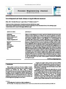
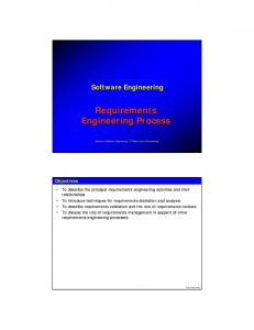
2.1 Basic concepts The proposed design process modelling approach is based on the transformational paradigm according to which each design process transforms a (possibly empty) set of products into another set of products: • a product is a document used, modified or produced during the life cycle of the information system; as we focus specifically on database specification, we will describe mainly database schemas and database-related texts such as DDL scripts, reports or application program sources. • a design process is described by the operations that have been carried out to transform input products into output products; each operation is in turn a process; atomic processes are called primitives, while the others will be called engineering processes; each process is supposed to be goal-driven, i.e., it tries to make its output products compliant with specific design criteria, generally called requirements [MYLOPOULOS 92]; • a product type describes the properties of a class of products that play a definite role in the system life cycle; a product is an instance of a product type; • a process type describes the general properties of a class of processes that have the same purpose, and that process products of the same type; a process is an instance of a process type; • the strategy of a process type specifies how any process of this type must be, or can be, carried out in order to solve the problems it is intended to, and to make it produce output products that satisfy its requirements; in particular, a strategy mentions what processes, in what order, are to be carried out, and following what reasonings. Only engineering process types are defined by a strategy. Primitive process types are basic types of operations that are performed by the analyst, or by a CASE tool. • Several product types can be given the same, or similar, properties. Hence the concept of product model. A model defines a general class of products by stating the components they are allowed to include, the constraints that must be satisfied, and the names to be used to denote them. A product type is expressed into a product model 2 • A set of product types and process types define a method. These concepts are sketched in Figure 1. Figure 2 illustrates this architecture through three examples. In hierarchy A, C++ programs form the model of source texts obeying the C++ syntax. Main is the class of main programs, while Invoice/v2.0 is a particular program from this class. Hierarchies B and C describe data models, classes of schemas and particular schemas according to the same three abstraction levels.
2.2 Short presentation of the MDL language MDL is both a non-deterministic and a semi-procedural language. It is non-deterministic when it describes processes to be freely performed by humans. In this case, the CASE tool behaves as an assistant that suggests what to do and not how to do it. MDL can also be semi-procedural when it forces the analyst to do things in a definite order. In many cases, procedural specifications can be a natural approach to solve some classes of problems in a reliable way. A method description is made of two parts. In the first one, product models are described. They are derived from the generic entity/object-relationship model (GER) described in [HAINAUT 89] which is aimed at describing information structures as well as processing units. A product model is made of a subset of the GER concepts onto which constraints are specified. These concepts are those of the GER model which are renamed. For instance, an entity type is called a 2
For practical reasons we did not find it necessary to define the concept of process model, at least in a first step, thus making the picture inelegantly asymmetrical. In particular, we identified a strong need for higher level abstraction above product types, while we found few convincing examples for process types.
table in a relational model and an object class in an OO model. The constraints defines the valid constructs of the specific model. For instance, a relational model has no relationship types and all the tables have at least one column.
Product Model
is of uses
Process Type
generates
instance of
Product Type
instance of uses
Process
generates
Product
Fig. 1 - The process modelling architecture
C++ programs
BINARY model is of
is of
is of
Local conceptual schema
Main
instance of Invoice/v2.0
A
ERA model
Optimized schema
instance of
instance of General Ledger
LIBRARY/Logical
B Fig. 2 - Three examples of product hierarchies
C
The second part of a method description concerns the process types. Like in most procedural languages, a process type as a signature and a body: • The signature is made of a name, and the list of product types they need as input, they produce in output or they can update. • The product types of the signature are locally defined; they specify the product model they are derived from, as well as an identifying name and the number of instance that are allowed (exactly one, at least one, between two and five, no limit,...). • The body is the strategy to be followed. This strategy is written in a traditional way, including some special instructions which are far less traditional. A strategy is a sequence of operations and control structures. • An operation can be: • a call to another process type • a call to a built-in function of the supporting CASE tool • a call to an external function written in the built-in language of the CASE tool • a call to the use of a toolbox. A toolbox is a list of tools of the CASE tool the user can use at a given time. When the execution of a process of this type reaches a call to a toolbox, the method is suspended and the hand is passed to the user who is allowed to do whatever he wants in the CASE tool using only the allowed tools. This corresponds to an engineering activity that could not be formalised (in reverse-engineering for instance). The process goes on until the user explicitly declares his job is done.
• Control structures are the traditional if...then...else, while, repeat, as well as some special non-deterministic structures as one (choose one process in the given list and do it), some (choose one or several processes in the given list) and each (do all the processes in the given list, but in any order). An example of MDL method can be seen in appendix. A summary of this method is shown on Figure 3. A more precise definition of the MDL language can be found in [ROLAND 97]. process LOGICAL_DESIGN strategy copy(Conceptual_schema,Raw_logical_schema); transfo_logical(Raw_logical_schema); copy(Raw_logical_schema,Logical_schema); toolbox TB_OPTIMIZATION(Logical_schema); end-process process PHYSICAL_DESIGN strategy copy (Logical_schema,Physical_schema); transfo_physical(Physical_schema); generate Standard_SQL(Physical_schema,SQL_script) end-process process ENGINEERING strategy new(Conceptual_schema); do LOGICAL_DESIGN(Conceptual_schema,Logical_schema); do PHYSICAL_DESIGN(Logical_schema,Physical_schema,SQL_script) end-process method perform ENGINEERING end-method Fig. 3 - Summary of a method
3. Histories The history of a database engineering process contains the trace of all the activities that were performed, all the products involved, all the hypotheses that were made, all the versions of the products resulting of those hypotheses as well as all the decisions taken. Naturally, the result is a complex graph. We will now examine more precisely what is in this graph, how it can be constructed and how it can be displayed. But first of all, we will see why we need histories.
3.1 Reusable histories An history can be reused in a great variety of ways, for different purposes, among which: • as it will be discussed in section 4.2, the history can be used to make the database project evolve • for documentation, it can simply be browsed or replayed • the history of a reverse engineering part can be inverted in order to generate a possible forward engineering process that could have been followed at development time; this new history can be reused for reengineering [HAINAUT 96b] • the history can be cleaned; all actions that do not participate directly to the development of the project can be removed; this comprises processes performed according to some hypotheses that were rejected in later decisions, some simple tests (just to see what it would give), some actions followed by their inverse due to backtracking,... This cleaning can be useful in order to generate examples or tutorials to learn new analysts how to do • it can be analysed in order to evaluate the quality of the work of the analyst • it can be analysed in order to evaluate the method and to improve it.
3.2 Basic elements The first basic elements of histories are processes. A history should contain all the processes that are performed during an engineering activity that complies with a method. The method being specified in a procedural language, the resulting
history is a tree of process calls. The whole project is made of processes, each of them being made of sub-processes and so on. Since a process is made of several sub-processes, it is useful to know in what order they have been performed, e.g., serially or in parallel. So each process will be stamped by its beginning date and time (mandatory) and end date and time. They will be identified by a name and the begin time stamp. In order to document his work, the analyst will add a description (some free text) to each process. As we saw in section 2, we have two kinds of processes: primitive processes at the operational level and engineering processes at the decisional level. A primitive process is a process performed using only primitives (built-in function of the CASE tool or external functions written in the built-in language of the CASE tool). It can be performed by an analyst when the method allows her to use a toolbox or by the CASE tool itself when the method calls built-in or external functions directly. The execution of primitives can be recorded in a log file. Since the history is aimed at being reused, both by analysts and by the CASE tool itself, the log file has to be readable, precise and complete. A text file with a well defined syntax and the possibility to add comments and bookmarks seems to be a good solution. Since the primitives are database schema transformations and since these transformations can be formally defined and are proved to be reversible [HAINAUT 96c], precision and completeness are straightforward if we store the signature of the transformations. In fact, we store more than just the signature because more information may be useful for reverse operations (e.g. it is necessary to keep the name of deleted attributes). Readability is achieved by the choice of a readable syntax for the transformation signatures and by the adjunction of comments. A short example of such a log file is shown on Figure 4. It shows how compound attribute Address of entity type BORROWER in schema LIBRARY/Conceptual is disaggregated: the three components of Address (Company, Street and City) are modified by changing of owner and name, then Address is deleted.
BORROWER Last_Name First_Name Address Company Street City
Í
BORROWER Last_Name First_Name Add_Company Add_Street Add_City
*TRF desagre_att %BEG %OWN "LIBRARY"/"Conceptual-1"."BORROWER"."Address" %PRE "Add_" &MOD SIA %BEG *OLD SIA %BEG %NAM "Company" %OWN "LIBRARY"/"Conceptual-1"."BOR ROWER"."Address" %END %NAM "Add_Company" %OWN "LIBRARY"/"Conceptual-1"."BOR ROWER" %CAR 1-1 %END &MOD SIA %BEG *OLD SIA %BEG %NAM "Street" %OWN "LIBRARY"/"Conceptual-1"."BORROWER"."Address" %END %NAM "Add_Street" %OWN "LIBRARY"/"Conceptual-1"."BOR ROWER" %CAR 1-1 %END &MOD SIA %BEG *OLD SIA %BEG %NAM "City" %OWN "LIBRARY"/"Conceptual-1"."BORROWER"."Address" %END %NAM "Add_City" %OWN "LIBRARY"/"Conceptual-1"."BOR ROWER" %CAR 1-1 %END &DEL COA %BEG %NAM "Address" %OWN "LIBRARY"/"Conceptual-1"."BORROWER" %PRV "LIBRARY"/"Conceptual-1"."BORROWER"."First_Name" %CAR 1-1 %END %END
Disaggregation transformation Beginning of the transformation signature The owner of attributes to promote is attribute Address of entity type BORROWER in schema LIBRARY/Conceptual-1 Attributes will be prefixed by "Add_" Now the details of the transformation : the first sub-attribute is promoted The old simple attribute to transform is identified by: its name its owner And this is its new name and its new owner
The same for the second sub-attribute
And the third one
Finally, the compound attribute is removed And all its characteristics are kept for possible reversing of the transformation Its name Its owner (schema and entity type) Its predecessor in the list of attributes of the entity type Its cardinality
Fig. 4 - A log fragment of a primitive process: disaggregation of compound attribute Address
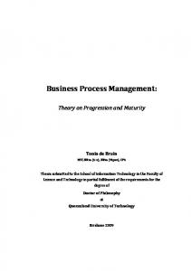
An engineering process follows a strategy given by the method. As the analyst who follows the method can make hypotheses, try different solutions and decide to abandon some of them, it is no longer possible to record actions in a linear way like in the log file. The history of an engineering process is a graph. Hence, the whole history is in fact a tree of graphs; leaf nodes are primitive processes with their log files and non-leaf nodes are engineering processes with their graphs as can be seen on Figure 5. Commonly, in software process modelling tools or business process modelling tools, engineering processes histories are well recorded, but they often use third party tools (editors, text processors, compilers, debuggers,...), the primitive processes in this paper, which have their own logging facilities, and all the logs are generally independent one from the other. In this paper, at the contrary, we link them all together in order to reuse them as a whole. LIBRARY New schema
LIBRARY/Conceptual
Logical design
LIBRARY/Optim. logical
Physical design
LIBRARY/Physical
Library.ddl/SQL
Logical design
Physical design
LIBRARY/Conceptual
LIBRARY/Optim. logical
Schema copy
Schema copy
LIBRARY/Raw logical
Basic logical design
Physical design
Generate SQL
Schema copy
LIBRARY/Optim. logical
LIBRARY/Physical
Logical optimization
Library.ddl/SQL
Fig. 5 - An engineering process tree The second basic elements of an history are the products. Since an analyst has the possibility to generate different versions of a product, they will be identified by their name and their version. For the same reason as processes, we will add some descriptions to products. A given product can be the result of several processes, but, at some definite time, the product has to be declared as finished. From that moment, the product is locked. It is no longer possible to modify it. Hence, each product must have a locked/unlocked state. The type (schema or text) of the product has no influence on the history. Finally, the third basic elements of an history are the decisions. A decision is a special kind of process, the sole difference being that it does not alter products, nor does it generate any product. There are two kinds of decisions. The first one is a decision that must be made according to the followed method. For instance, when the condition of an if or a while statement needs a response of the analyst (if ask("Do you want to optimise the relational schema ?")...). The second kind of decision is one that follows hypotheses. When an analyst has to perform a process, she can make different hypotheses and perform the same process several times with each hypothesis in mind. The description of each process will contain the hypothesis. Each process will generate its own version of the products. When all the processes are over, the analyst chooses one version among all to continue her work. The process of decision will show the choice and its description will contain the rationales that lead to that choice. This second kind of decision is not linked to the followed method, it can be made at any time.
3.3 History representation As we saw above, an history is a tree of graphs and log files. This tree is like the table of contents of the project, the graphs and the log files being the real material. We will now examine different ways of representing them in different situations, with different purposes in mind. The simplest way of showing a table of contents is a textual way, like in every book: the name of every process at the top most level are listed in the order the processes were performed; under each of them, the list of sub-processes they are made of, also sorted in performance order, and so on. To each process name in the list, we add a reference (hyperlink) to the process description (a graph for engineering processes or a log file for primitive processes). Figure 6 shows an example of such a tree. Since a log file is a readable text file, a simple text browser is the simplest way of showing it. But such a file can be very long (a simple schema transformation needs a lot of information to be recorded in order to be replayed correctly or even reversed) and tedious to read. So, browsing through it is not very useful. In fact, those log files are also built to be easily reused by tools. They can be built-in in the supporting CASE tool, but also written by the analysts for their own special purposes. We will see a few tools later. For the person who browses an history, the very small details of the process execution are not always necessary. To know what a primitive process does (and not how it is done) is very often enough. Hence, to give a meaningful name to the process and to write a short description are good habits and showing only them will usually be quite satisfying.
Fig. 6 - An example of history tree Engineering processes are the most interesting parts of an history. They not only show in what order processes were performed (as in the tree) but also what products were used, modified or produced, what hypotheses were made, what decisions were taken. Engineering processes contain all the intelligence of the project, all the information that is sufficient to understand how the project was conducted and why it was that way. For greater readability, we will represent these engineering processes in a graphical way. Sub-processes will be shown as rectangles, products as ellipses and decisions as pentagons that look like upside down houses. As important as those basic elements are the links between them. The most intuitive links are certainly the input/output links. The basic view of an engineering process graph shows input/output links, an example of which is shown in Figure 7. On this drawing, we can see how a reverse engineering process was performed. All available information were extracted from an SQL database creation script (library.ddl), the result being a new database schema (LIBRARY/Extraction). The database is used by a program called library.cob; a reference to this file is added to the history. Extract SQL and New text are primitive processes. On the basis of the last file, the schema is enriched. But this enrichment process is a long task (schema enrichment is an engineering process) which involves a lot of intelligence. So, several alternative solutions are possible. In Figure 7, we can see that the analyst did the job twice. The description attached to both processes should describe what has been done in each of them, what makes one different from the other. The two processes generates two different versions of a product (LIBRARY/1 and LIBRARY/2). After evaluation, it seems that the second version is the best; this is documented with the pentagon, simple arrows showing what products entered in the choice, the double headed showing what product (possibly several) was chosen. The basic view is ideal for working, but we may need, for some reasons (specially on bigger projects), simplified views. A product only view is one of them. In Figure 8,we can see a product only view of the same project as in Figure 7. The arrows show the dependencies between products: LIBRARY/Extraction is made on the basis of library.ddl and LIBRARY/1 and LIBRARY/2 are both made on the basis of LIBRARY/Extraction and library.cob/1. Figure 8 shows a derived view of the current process. But, It may sometimes be useful to have an idea of the dependencies between all products in the whole project. We can summarise the whole tree of graphs in a single product
dependency graph. For instance, Figure 9 shows the dependencies between all the products in the project shown in Figure 5. To obtain this graph, let us flatten the tree. Let us take the graph of the root process in the tree and let us replace all its engineering process rectangles by their graphs. Let us do the same on the result recursively until there are no more engineering processes in the graph. Removing primitive processes and drawing the dependencies they induce will give the result. library.ddl/SQL
Extract SQL
New text
LIBRARY/Extraction
library.cob/1
Schema enrichment
Schema enrichment
LIBRARY/1
LIBRARY/2
LIBRARY/2 seems more realistic
Fig. 7 - An example of engineering process basic view library.ddl/SQL
LIBRARY/Extraction
library.cob/1
LIBRARY/1
LIBRARY/2
Fig. 8 - An example of product only derived view LIBRARY/Conceptual
LIBRARY/Raw logical
LIBRARY/Optim. logical
LIBRARY/Physical
mfpe 99.ddl/SQL
Fig. 9 - An example of summarised derived view
4. History construction In this section we will see how histories are build by the supporting CASE tool, through the illustration of a short method specified in MDL. Though the database of an information systems can be claimed to be build carefully, it will have to evolve along the years. When the project begins, the analyst follows the chosen method in order to build his database schema. In parallel, the history of this process is recorded, documenting the job in a precise way. When the
database has to evolve, this documentation is reused to guide the modifications, so that the history has to be updated too. We will examine both situations: development and evolution of a database structure.
4.1 Building a new database An MDL method can be strongly imperative (using classical control structures such as sequences, if...then...else or while loops with strong3 conditions) or, on the contrary, very flexible, i.e., using permissive structures such as do-one, dosome, do-each, if...then...else or while with weak4 conditions). In the first case, the CASE tool is instructed what to do so that it can perform the process automatically. Let us examine the history shown in Figure 5. The project uses the simple forward engineering MDL method listed in appendix and summarised in Figure 3. The history tells us that the following events occurred: 1. the CASE tool created automatically the Library project process (asking the analyst for the process name); 2. the New schema sub-process was created (asking for the schema name); 3. the analyst was allowed to enter the components of the new schema (a toolbox comprising the schema editing functions was the only available process); 4. when the user completed the schema, he told the CASE tool to close the current process and to go on; 5. the CASE tool automatically created the Logical design engineering process, into which it made a copy of the schema; 6. the Basic logical design was performed on the basis of a script of transformations5 explicitly defined in the method 7. the resulting schema was copied (Library/Optim. logical); 8. the user was allowed to manually optimise the schema; this optimisation needs complex reasonings that could not be translated into an automatic procedure; 9. when the analyst finished his job, the schema was automatically used as the output product of the Logical design process and return to the Library Project process; 10. the last schema was passed as input to a new Physical design process, that was performed entirely automatically; 11. two products generated in Physical design are used as outputs of Physical design and returned to Library Project; 12. the project was terminated. This example is an illustration of a straightforward process, in which the involvement of the analyst is reduced to the minimum; he has no action on the way the method is followed. At the opposite, the method can give the analyst the opportunity to decide how he wants to conduct the project. Let us look at the excerpt of a process type strategy shown on figure 10.a. It contains a repeat...until loop that is controlled by a weak condition. In the body of the loop, the do-some structure allows the analyst to perform, one, two, three or four of the proposed processes so that he can perform them in the order he prefers. When the CASE tool reaches that point of the method, it enters in the repeat loop and, to perform the do-some structure, it gives the analyst the list of the four candidate processes. The analyst picks one process type in the list and performs it. When finished, the CASE tool gives him the list a new time (without the already chosen process types) and the user can make a new choice or go on. When he goes on, the end of the loop is reached and the condition is evaluated: the CASE tool asks the given question to the user who has to answer yes or no. All four sub-processes update the COBOL_schema. So, a history that follows this process type excerpt could look like in Figure 10.b. We saw in section 3 that an analyst has the possibility to explore several branches of the solution space. Practically, he is allowed to perform the same process several times according to different hypotheses and to decide later on what will be the winning solution on the basis of the results of each process.
4.2 Database evolution project Some times after a database was created, the database is naturally asked to evolve in order to satisfy new requirements. In this respect, the history built during the creation will be reused and updated. In fact, a new engineering branch will be
3
A strong condition is evaluated by the CASE tool (by example, are there tables in the schema that are not linked to another one by a foreign key ?) and its result is definitive. 4 A weak condition can be evaluated by both the CASE tool or the analyst. When the evaluation is done by the CASE tool, the result is show to the analyst who can decide otherwise. The CASE tool gives an advise and the analyst decides. 5 The DB-MAIN CASE tool [HAINAUT,94] is transformation-based, i.e., it offers a series of elementary reversible transformation functions that allow an analyst to transform selected constructs in a schema.
developed starting from a copy of the schema to be updated. Indeed, since the current schema has been implemented, it has been locked and cannot be updated. The major part of the work that has been done from that point in the original history should be redone in the new branch too. In this objective, the analyst will replay the old history: every action performed from that point in the old history will be performed in the new branch too, except for the constructs that have been updated. In the latter case, the analyst have to manually process the new components. Moreover, the replayed history can be simplified. If, in the first time, the analyst had to try several hypotheses, now that he knows which one is the best, he does not need to replay the others. It is worth noting that generating a new version of a product to be modified looks very similar to making several hypotheses. The only difference is that no decision is taken afterward. repeat some do refine_filler_attribute (COBOL_schema); do refine_cardinalities (COBOL_schema); do refine_identifiers (COBOL_schema); do search_for_foreign_key (COBOL_schema); end-some do check_consistency(COBOL_schema) end-repeat until (ask "Do you want to go on ?") a. An excerpt of process type strategy COBOL_schema/1
Identifiers refinement
Foreign keys research
One table not linked to others
More foreign keys research
b. An example of history following the above method excerpt Fig. 10 - An example of weakly constrained process type
5. Conclusion Although histories are very often treated as simple technical aspects, we tried to show in this paper that defining its format, its information contents and its display formats are major issues in CASE, and that the topic deserves being carefully studied: • a history should reflect the method it follows; • it should also reflect human uncertainties, reasonings and decisions; • it should distinguish strategic actions from simple technical actions; • it has to be readable in order to be reused by human beings; • it has to be complete, precise and correct to be reused by tools; These principles have been implemented into the DB-MAIN method-driven CASE environment. This tool uses MDL script to guide analysts when they perform database engineering projects. It includes a sophisticated history processor that is in charge of recording, processing and replaying histories. While not yet commercially available, DB-MAIN is already used for production by several enterprises, both for forward and reverse engineering of database applications.
6. Bibliography [CURTIS 92] B. Curtis, M. I. Kelner, J. Over, Process Modeling, Communications of the ACM, September 1992, Vol.35 No.9. [ENGELS 94] Gregor Engels and Luuk P.J. Groenewegen, SOCCA: Specifications of Coordinated and Cooperative Activities, in A.Finkelstein, J.Kramer, and B.A. Nuseibeh, editors, Software Process Modelling and Technology, pages 71--102. Research Studies Press, Taunton, 1994.
[ESTUBLIER 94] Jacky Estublier and Rubby Casallas, The Adele Configuration Manager, in Tichy editor, Configuration Management. John Wiley & Sons, 1994. [GROSZ 96] G. Grosz, S. Si-Said, C. Rolland, Mentor : un environnement pour l'ingénierie des méthodes et des besoins, INFORSID’96, Bordeaux, 4-7 juin 1996. [HAINAUT 89] J-L. Hainaut, A Generic Entity-Relationship Model, in Proc. of the IFIP WG 8.1 Conf. on Information System Concepts : an in-depth analysis, North-Holland, 1989. [HAINAUT 94] J-L. Hainaut, V. Englebert, J. Henrard, J-M. Hick, D. Roland, Evolution of database Applications : the DB-MAIN Approach, in Proc. of the 13th International Conference on ER Approach, Manchester, Springer-Verlag, LNCS 881, 1994 [HAINAUT 95] J-L Hainaut, V. Englebert, J. Henrard, J-M. Hick, D. Roland, Requirements for Information System Reverse Engineering Support, in Proc. of the IEEE Working Conference on Reverse Engineering, Toronto, IEEE Computer Society Press, July 1995 [HAINAUT 96a] Hainaut J.-L., Englebert V., Henrard J., Hick J.-M., Roland D., Database Reverse Engineering : from Requirement to CARE tools, Journal of Automated Software Engineering, 3(2), 1996, Kluwer Academic Press. [HAINAUT 96b] Hainaut J.-L., Henrard J., Hick J.-M., Roland D., Englebert V., Database Design Recovery, in Proc of the 8th Conf. on Advanced Information Systems Engineering (CAISE’96),Springer-Verlag, 1996. [HAINAUT 96c] Hainaut J.-L., Specification preservation in schema transformations - Application to semantics and statistics, Data & Knowledge Engineering, 16(1), 1996, Elsevier Science Publish. [HENRARD 95] Henrard, J., Englebert, V., Hick, J.-M., Roland, D., Hainaut, J.-L., DB-MAIN: un atelier d'ingénierie de bases de données, in Proc. of the "11èmes journées Base de Données Avancées", Nancy (France), September 1995. [HENRARD 96] Henrard J., Hick J.-M., Roland D., Englebert V., Hainaut J.-L., Techniques d’analyse de programmes pour la rétro-ingénierie de base de données, submitted to INFORSID’96, 1996. [JARKE 93] M. Jarke, editor. Database Application Engineering with DAIDA , Springer - Verlag, 1993. [MAYER 98] R. J. Mayer, P. C. Benjamin, B. E. Caraway and M. K. Painter, A Framework and a Suite of Methods for Business Process Reengineering, www.idef.com/articles, October 30, 1998. [MYLOPOULOS 92] J. Mylopoulos, L. Chung, B. Nixon, Representing and Using Nonfunctional Requirements: A Process-Oriented Approach, IEEE TSE, Vol. 18, No. 6, June 1992. [NATURE 96] Nature Team, Defining Visions In Context: Models, Processes And Tools For Requirements Engineering, Infirmation Systems, Vol. 21, No 6, 1996. [POTTS 88] C. Potts, G. Bruns, Recording the Reasons for Design Decisions, in ICSE 88, 1988. [ROLAND 95] D. Roland, Un langage de description de processus : définition des prédicats structurels, technical report, septembre 1995. [ROLAND 97] D. Roland, J.-L. Hainaut, Database Engineering Process Modelling, Proceedings Of The First International Workshop On The Many Facets Of Process Engineering, Gammarth, Tunisia, September 22-23, 1997. [ROLLAND 93] C. Rolland, Modeling the Requirements Engineering Process, in 3rd European-Japanese Seminar on Information Modeling and Knowledge Bases, Budapest, May 1993. [ROLLAND 95] C. Rolland, C. Souveyet, M. Moreno, An Approach For Defining Ways-Of-Working, Information Systems, Vol. 20, No. 4, pp. 337-359, 1995. [ROLLAND 96] C.Rolland, L'ingénierie des processus de développement de système : un cadre de référence, Ingénierie des systèmes d'information, Vol. 4, No 6, 1996. [ROLLAND 97] C. Rolland, A primer for method engineering, CREWS Report Series 97-06, Proceedings of the conference INFORSID, Toulouse, France, June 10-13, 1997. [ROSENTHAL 94] A. Rosenthal, D. Reiner, Tools and Transformations - Rigourous and Otherwise - for Practical Database Design, ACM TODS, Vol. 19, No. 2, June 1994
[SOUQUIERES 93] J. Souquières, N. Lévy, Description of Specification Developments, in Proceedings of RE'93, San Diego (CA), 1993. [WANG 95] X. Wang, P. Loucopoulos, The Development of Phedias: a CASE Shell, Proceedings of the Seventh International Wokshop on Computer-Aided Software Engineering, Toronto, July 10-14, 1995. [YONESAKI 93] N. Yonesaki, M. Saeki, J. Ljungberg, T. Kinnula. Software Process Modeling with the TAP Approach - Tasks-Agents-Products, in 3rd European-Japanese Seminar on Information Modeling and Knowledge Bases, Budapest, May 1993.
Appendix: A simple forward database engineering method % Product models definitions %%%%%%%%%%%%%%%%%%%%%%%%%%%% text-model SQL_FILE title "SQL file" description An SQL script containing SQL instructions for the creation of a database including create database, create table, create index, alter table with checks, create trigger,... end-description extensions "SQL", "DDL" end-model schema-model PHYSICAL_SCHEMA title "SQL schema model" concepts project "database" schema "view" entity_type "table" atomic_attribute "column" constraint "constraint" identifier "key" primary_identifier "primary_key" access_key "key" constraints ET_per_SCHEMA (1 N) % At list one table required diagnosis "Schema &NAME should have a table" RT_per_SCHEMA (0 0) % No rel-type allowed diagnosis "Rel-type &NAME should not exist" ATT_per_ET (1 N) % At least one column per table diagnosis "Table &NAME should have at least one column" PID_per_ET (0 1) % At most one primary ID per table diagnosis "Table &NAME has too much primary identifiers" SUB_TYPES_per_ISA (0 0) % Is-a relations are not allowed diagnosis "Is-a relations are not allowed and &NAME has a sub-type" ID_NOT_KEY_per_ET (0 0) % Every identifier is an access key diagnosis "Identifier &NAME should be an access key" OPT_ATT_per_EPID (0 0) % Optional columns not allowed in primary ids. diagnosis "There should be no optional column in primary id &NAME." DEPTH_of_ATT (1 1) and MAX_CARD_of_ATT (1 1) % Columns are atomic and single-valued diagnosis "Column &NAME should be atomic and single-valued." ALL_CHARS_in_LIST_NAMES (ABCDEFGHIJKLMNOPQRSTUVWXYZabcdefghijklmnopqrstuvwxyz0123456789$_) and NONE_in_LIST_NAMES (_$,$$) and LENGTH_of_NAMES (0 31) and NONE_in_FILE_CI_NAMES (PHYSRDB.NAM) diagnosis "The name &NAME is invalid" end-model schema-model LOGICAL_SCHEMA title "Logical relational schema" concepts project "database" schema "view" entity_type "table" atomic_attribute "column" constraint "constraint" identifier "key" primary_identifier "primary_key" access_key "key" constraints ET_per_SCHEMA (1 N) % At list one table required diagnosis "Schema &NAME should have a table" RT_per_SCHEMA (0 0) % No rel-type allowed diagnosis "Rel-type &NAME should not exist" COLL_per_SCHEMA (0 0) % No collection allowed diagnosis "The schema should have no collection" ATT_per_ET (1 N) % At least one column per table diagnosis "Table &NAME should have at least one column" PID_per_ET (0 1) % At most one primary ID per ET diagnosis "Table &NAME has too many primary identifiers" KEY_per_ET (0 0) % No access keys diagnosis "Table &NAME should not have an access key" SUB_TYPES_per_ISA (0 0) % Is-a relations are not allowed diagnosis "Is-a relations are not allowed and &NAME has a sub-type" OPT_ATT_per_EPID (0 0) % Optional columns not allowed in primary ids. diagnosis "There should be no optional column in primary id &NAME."
DEPTH_of_ATT (1 1) and MAX_CARD_of_ATT (1 1) % Columns are atomic and single-valued diagnosis "Column &NAME should be atomic and single-valued." end-model schema-model CONCEPTUAL_SCHEMA title "Conceptual schema model" concepts project "project" schema "schema" entity_type "entity type" rel_type "relationship type" atomic_attribute "attribute" compound_attribute "compound attribute" role "role" group "group" constraint "constraint" constraints ET_per_SCHEMA (1 N) % At list one ET required diagnosis "Schema &NAME should have an entity type" COLL_per_SCHEMA (0 0) % No collection allowed diagnosis "The schema should have no collection" ATT_per_ET (1 N) % At least one attribute per ET diagnosis "Entity type &NAME should have at least one attribute" KEY_per_ET (0 0) % No access keys diagnosis "Entity type &NAME should not have an access key" REF_per_ET (0 0) % No foreign key diagnosis "Entity type &NAME should not have a foreign key" ID_per_ET (1 N) % If there are identifiers, one of them is primary and PID_per_ET (1 1) or ID_per_ET (0 0) diagnosis "One of the identifiers of entity type &NAME should be primary" EMBEDDED_ID_per_ET (0 0) % Embedded identifiers are not allowed" diagnosis "Embedded identifiers should be removed in entity type &NAME" ID_DIFF_in_ET (components) % All identifiers must have different components diagnosis "Identifiers made of the same components should be avoided in &NAME" TOTAL_in_ISA (no) % Total is-a relations should concern at least or TOTAL_in_ISA (yes) % two subtypes and SUB_TYPES_per_ISA (2 N) diagnosis "Total is-a relations are not allowed with only one sub-type" DISJOINT_in_ISA (no) % Disjoint is-a relations should concern at least or TOTAL_in_ISA (yes) % two subtypes and SUB_TYPES_per_ISA (2 N) diagnosis "Disjoint is-a relations are not allowed with only one sub-type" ROLE_per_RT (2 2) % 2