command shaping filter is used to generate a smooth and reahzable tip reference trajectory for a tip-based .... crete time block diagram representing tim con-.
Journal of Meehamcal Sctence and Technology, Vot 19, No 1, (Special E&tton) pp 357~363, 2005 357
Model-based Reference Trajectory Generation for Tip-based Learning Controller Snngsoo Rhim, Soon Geut Lee * School of Mechamcal and Industrtat Systems Engineering, Kyung Hee Universtty, Yongin 449 701, Korea Tae Gyoon Lim Research Institute of Industrial Sczence and Technology, Pohong 790-600, Korea
The non-minimum phase charactertstlc of a flexible mampulator makes ta ackmg control of ~ts ttp difficult The level of the ttp tracking performance of a flexible mampulator is significantly affected by the charactertstlcs of the tip reference trajectory as well as the characteristics of the flexible manipulator system Th~s paper addresses the questmn of how to best specify a reference trajectory for the tap of a flexible mampulatoa to follow an order to achieve the objectives of reducing
tap tracking error, residual t~p vabtataon, and the required actuation efiort at the
manipulator joint A novel method of tap-based learnmg controller for the flexible manipulator system is ploposed an the paper, where a model of the flexible mampulator system with a command shaping filter is used to generate a smooth and reahzable tip reference trajectory for a tip-based learmng connoller
Key W o r d s : C o m m a n d Shaping, Tip Control, Flexabte Lank, Learning Control the base motion requared to achieve it wall gener-
1. i n t r o d u c t i o n
ally not follow that same aeference trajectory, especially in the case of high-speed, high-acc-
The common difficulty reported when using
eleration reference motmns To achaeve more ac-
varmus control schemes to achieve fast yet accurate tap p o s m o n m g of a flexible mampulator as
curate and more direct posttmn control of the tap
the presence of the motmn-mduced residual vi-
where the most of the uselhl work ts done a tapbased-conn ol appl oach seems more feasible than
brations an the mampulator in a typical configu-
a joint-based-control approach A ttp~ased con-
rattan the manipulator is actuated at the end of
troller obviously requires a reference for the ttp
the hnk opposite the tip (t e at the "base" or joint
to be regulated based upon and the questton is
end) and what results - an the case wheae accurate
what to use For the tap tracking problem, many
positioning of the t~p ~s of mterest
as a non-
researchers focused on the development of control
collocated control problem The base and up mo-
method dcstgn assuming given random smooth
tions an a flexable manipulator are typacally out
reference input The level of the ttp tracking per-
of phase and may oppose one another
formance of a flexible mantpulatm Is s~gmficant-
gaven a
destred reference trajectory foa the np to follow,
ly affected by the charactertstacs of the tap reference trajectory as well as the charaeterasttcs of
* Collespondtng Author, E-raM1 sglee@khu ac t~r "IEL +82-31-201-2506, FAX +82-31-202-1204 School of Mechameal and Industrial Systems Engineerrag, Kyung Hoe Umverstty, Yongm 449 70l, Korea (Manuscript Received Novembei 29, 2004, Revised Dccomber 15, 2004)
the flexable mampulator system Manapulator refo erence tlakectorles are typically designed to optimize the dynamacs capabahttes of the actuato~ at the base, m which case their use as the tip reference tlajectory might be physically unrealazable Gtven a petmdtc desired reference trajectory to
Copyright (C) 2005 NuriMedia Co., Ltd.
358
Sungsoo Rhim, Soon. Geul Lee and Tae Gyoon Lira
be tracked by the tip, the controller in (Hu, 2000) used repetitive learning control to determine the corresponding base motion required. Though effective in the objective of attenuating tip tracking error, the method required a relatively large, sometimes prohibitive, control effort at the joint actuator (needed in order to cancel out vibrations at the manipulator tip) and was also relatively ineffective at suppressing residual tip vibration. By properly designing the tip reference trajectory, it is possible to overcome these two undesirable effects. This paper addresses the question of how to best specify a reference trajectory for the tip
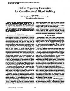
in this paper is shown Fig. 1. it is assumed that the system possesses a single dominant elastic mode. Such systems may be modeled as a system of two masses coupled by a linear spring and a linear damper acting in parallel, as shown in Fig+ 2. The mass m, is located at the actuator (which applies to it a control force u) and represents the base of the manipulator. The mass ma represents the manipulator tip. The flexibility of the manipulator is modeled with the spring (k) and. damper (b, usually a relatively small quantity). The displacement of the base mass and the tip mass, each measured from a fixed position
of a flexible manipulator and proposes a novel configuration of tip-controller that utilizes a model-based tip reference trajectory generation method in order to achieve the objectives of reducing tip tracking error, reducing residual tip vibration, and reducing the required actuation effort (or motion) at the base. In our new tipbased controller, a model of the flexible manipulator system is used to generate a smooth and realizable tip reference trajectory which is to be tracked by the tip of the actual system. With a properly designed command shaping filter (Singer, 1990) implemented in the model the tip response of the model is free of residual vibration. Then a multirate repetitive learning controller (MRLC) is used to ensure that the tip response of the actual system follows the smooth and vibration-free tip response of the model. In the following sections of the paper, the dynamics of the flexible manipulator system is described first and the description of the model-based reference trajectory generation method using a command shaping filter follows. Then follows the proposed flexible naanl]pulator t~,p controller has ed on repetitive learning control and the use of the tip reference trajectory generated from the model. Simulation results utilizing the proposed tip-based controller are subsequently presented and discussed.
for which the spring is unstretched, are denoted by X~ase and x,~. Their respective velocities are 2ba,e and 2~i~, where 9 denotes differentiation with respect to time, t. The control force u is used to drive the base mass in such a way that results in the tip mass precisely tracking a desired reference trajectory. As a result, for later use in the control method formulation, as well as in subsequent numerical simulations, it is necessary to determine the (linear) dynamics between u and xtio. The lbllowing two transfer functions are computed for this purpose :
yo
L
Fig, 1 Gantry type flexible manipulator system
b
2. Dynamics of Flexible Manipulator
~t
L
The flexible manipulator system of our interest
Fig. 2
Copyright (C) 2005 NuriMedia Co., Ltd.
k
A mass spring damper model of flexible link
Model based Reference Trajectory Generationibr Tip based Learning Controller
(i)
G~ (s) - X,,.~.(s) / U ( s) G2(s) = X . ~ (s) / X , , ~
(s)
(2;1
where s is the Laplace variable. The equations of motion in state-space form for the two mass system shown in Fig. 2 are given by 5~-Ax+bu where x - - [ x b , , ~ x~,:o s
(3) 2,~1 r, b = [ 0
359
actnat flexible manipulator system whose transfer functions are calculated in the previous section. A slandard PD feedback contro|ler, D(z), is used to apply the required control force to the base (joint) mass. Conventionally / ) ( z ) is modeled as a PD controller with an added one step time delay :
D(z)=:(AStKa(1-z-~)/T)z '
0 l/m~
(8)
O] T, and A=
l
00
00
01
01
k/m, k,..'mj b/m~ b/ I'141 k/me - k / m 2 b/m2 -b/maJ
(4)
Taking the input to be zt and the output to be Xb,~s~, it is tound that the transfer ]\ruction Gt (s)-Xb~s~(s)/U(.s) is given by
s~+ (bim2)s+kim.e
C, I.,~)- ij;lli : . b! .$4_ Ai _-,
j;l,l Aftb./JJ~2)S,/~- {te."*Jll+~,/'~:'S 2'i (5)
The second transfer flmction is obtained by considering the base mass position as the input and the tip mass position as the output. The resulting equation of motion is given by
The corresponding transler (;,2(s) is G(s) -
I bl'ma) s + k/'n%
sz + (b/ mz) s+ k/m2
(7)
The control formulation and numerical simula tions appearing in the following sections of this paper will take place in the discrete-time domain, since the future plan is t o hnplement the developed control method digitally on an experimental test bed manipulator. Therefore, discretetime equivalents of the transfer functions and Gt(S) and Ga(s) will actually be used.
where T is the discrete time sample period and Kp and Is are constant control gairs. The discrete time block diagram representing tim control system proposed in this paper i:; shown in Fig. 4. Tile system is comprised of the flexible manipulator tip controller and the tip reference trajectory generation part including the model of the manipulator. In Fig. 4, G~(z) and G2 represent a model of Gl(z) and G2(z), C(z) represents a command shaping filter. Command shaping, a feedlorward approach, seeks to ]educe tip vibrations by reshaping the desired trajectory to be tracked by the joint in order to produce a new trajectory that will not excite the resonances of the tqexible manipulator, Thus s the calculated tip response of a model system with a well-designed filter C ( z ) . should show no residual vibration 9 To apply more direct regulation on the ]notion of the tip, we suggest the use of -~e,p as a reference trajectory for the lip control. We know that ,re@ is nearly guaranteed to be
Y;'e~"
Fig. 3
Block diagram of conventional j3int control system
+. > . . . . .
3. Control Formulation
.; ?(~,
W
. cal sImulanons take place in the discrete-tame domain and the sample permd used as 0 001 see Discrete-time eqmvalents of the plant transfer
poslt~ve Impulse fikms have been observed to exhibit very similar responses Lastly, to simulate a more reahstic contro| environment, noise has been modeled at the base actuator and at the tip position measurement
4.1 Configuration The system parameters used m the numermal simulations are base mass m~--8 kg, tip mass m 2 = 2 kg, damping ratm s'-b(2rn~co~) = 0 005, and natural frequency of the elastic mode wn =
ff-/e/mz--62 96 rad/s
Copyright (C) 2005 NuriMedia Co., Ltd.
~6~
Sungsoo Rhim, Soon-Geul Lee and Tae Gyoon Lira
Results The periodic joint reference trajectories used in the numerical simulations appear in Fig. 6. Shown are both the unfiltered reference trajectory )2ref and the corresponding filtered trajectory x/~tt. :er~ is an offset sinusoid with flequency 5re r a d / sec alternating with zero-velocity segments. The amplitude of displacement is 0.050 m and the period is 1 sec. Fig. 7 shows the tip responses of the actual system and the model. In plot (a), the dotted line represents the tip response in the model and the effect of the filtered input is evident. The filter is able to successfully suppress the 4.2
005
,
o.o4l
"",
g,r~ered
9
'...........................................]
0~:,i ",
{
"hill A . - P and N. Sadcgh, 2000, " N o n - C o located Control of a Flexible-Link Manipulator Tip Using a Muhirate Repetitive Learning Contrailer," The 7 th Meehatronies Forum Interna-
tional Conference, Atlanta, GA. Magee, D. P. and Book, W.J., 1998, "Optimal Filtering to Minimize Elastic Behavior in Serial Link Manipulators," Proceedings of the American Control Conference, Philadelphia, PA, pp. 2637-2642. Rhim, S., Hu, A. P., Sadegh, N. and Book, W.J., 2001, "Combining a Multirate Repetitive Learning Controller with Command Shaping for hnproved Flexible Manipulator Control,"
A S M E Journal of Dynamic Systems, Measurement, and Control, Vol. 123, pp. 385-~390. Sadegh, N., Hu, A . - P . and James, C., 2002, "Synthesis, Stability Analysis, and Experimental Implementation of a Multirate Repetitive Learning Controller," A S M E Journal of Dynamic Systems, Measurement, and Control, Vol. 124, pp. 668~674. Singer, N. C, and Seering> W.P., 1990, "Preshaping Command Inputs to Reduce System Vibration," A S M E Journal of Dynamic Systems, Measurement, and Control, Vol. 112, lOP, 76~82. Singer, N.C., Singhose, W, and Seering, W,, 1999, "Comparison of Filtering Methods for Reducing Residual Vibrations," European Journal of Control, Vol. 5, pp, 211~218. Tomlzuka, M., 1987, "Zero-Phase Error Tracking Algorithm for Digital Control," A S M E
Journal of Dynamic Systems, Measurement, and Control, Vol. 109, pp. 65~68.
Copyright (C) 2005 NuriMedia Co., Ltd.