Model-Driven Derivation of Product Architectures Goetz Botterweck
Liam O’Brien
Steffen Thiel
Lero University of Limerick Limerick, Ireland
Canberra Research Laboratory National ICT Australia Canberra, Australia
Lero University of Limerick Limerick, Ireland
[email protected]
[email protected]
[email protected]
ABSTRACT Product Derivation is one of the central activities in Software Product Lines (SPL). One of the main challenges of the process of product derivation is dealing with complexity, which is caused by the large number of artifacts and dependencies between them. Another major challenge is maximizing development efficiency and reducing time-to-market, while at the same time producing high quality products. One approach to overcome these challenges is to automate the derivation process. To this end, this paper focuses on one particular activity of the derivation process; the derivation of the product-specific architecture and describes how this activity can be automated using a model-driven approach. The approach derives the product-specific architecture by selectively copying elements from the product-line architecture. The decision, which elements are included in the derived architecture, is based on a product-specific feature configuration. We present a prototype that implements the derivation as a model transformation described in the Atlas Transformation Language (ATL). We conclude with a short overview of related work and directions for future research.
Categories and Subject Descriptors D.2.13 [Software Engineering]: Reusable Software – Domain engineering, Reuse models; D.2.2 [Software Engineering]: Design Tools and Techniques – Computer-aided software engineering (CASE); D.2.11 [Software Engineering]: Software Architectures – Languages.
General Terms Design, Languages.
Keywords Product Derivation, Model-Driven Approaches, Model Transformation, ATL, Software Product Lines, Software Architectures.
1. INTRODUCTION Software product line engineering (SPLE) aims to develop software applications and software-intensive systems using platforms Permission to make digital or hard copies of all or part of this work for personal or classroom use is granted without fee provided that copies are not made or distributed for profit or commercial advantage and that copies bear this notice and the full citation on the first page. To copy otherwise, or republish, to post on servers or to redistribute to lists, requires prior specific permission and/or a fee. ASE’07, November 5–9, 2007, Atlanta, Georgia, USA. Copyright 2007 ACM 978-1-59593-882-4/07/0011...$5.00.
and mass customization [3, 11]. A key concept of SPLE is the strategic reuse of a shared set of assets. The activities revolving around the creation and usage of these assets can be structured into two main areas: Domain Engineering creates artifacts which cover the whole product line, for instance the Domain Requirements, which describe the overall requirements for all products in a product line, the Domain Architecture, which sets structures and constraints for all products and Domain Components, which can be (re-) used during the realization of the products. Application Engineering then takes these shared assets and creates a particular product from them [11]. A central activity within application engineering is Product Derivation, which includes the derivation of application artifacts from domain artifacts, for instance the derivation of Application Requirements from Domain Requirements, the derivation of the Application Architecture from the Domain Architecture and the derivation of Application Components from Domain Components. One of the main challenges of the process of product derivation is dealing with complexity, which is caused by the large number of artifacts and dependencies between them. Another major challenge is maximizing development efficiency and reducing timeto-market, while at the same time producing high quality products. While product derivation involves the derivation of all kinds of application-specific artifacts, here we focus on the derivation of the application architecture. So we are trying to solve the following research problem: Given a Domain Architecture and application-specific requirements as input, how do you create the Application Architecture based on these inputs? And how do you automate that process as much as possible? The remainder of the paper is structured as follows: In order to describe the automation process we first outline (meta-) models which are used within the approach (Section 2). We then present our derivation approach and the model transformations used within it (Section 3). We discuss our approach (Section 4) and finish with related work (Section 5) and a conclusion (Section 6).
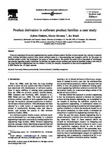
2. THE UNDERLYING METAMODELS 2.1 Feature Models The feature metamodel (left half of Figure 1) defines the language elements that are available to describe both the Domain Feature Model and the Application Feature Model. The base structure of a feature model is a hierarchy of FeatureComponents, which can be either FeatureGroups (containing more FeatureComponents) or Features. The Model is a special form of FeatureGroup.
Figure 1. Metamodels for the feature model and the architecture model and the relationships between them. For our prototype we limit ourselves to simple features, which can be switched on or off. So for an Application Feature Model the Features can be described a selected (.selected=true) or deselected (.selected=false). All these attributes together describes the feature configuration for a particular product. This feature configuration has to be determined based on the Application Requirements. This part of the derivation, deciding which features are required to fulfill the requirements is beyond the scope of this paper. See [5, 9] for more details.
2.2 Architecture Models The architecture metamodel (right half of Figure 1) defines the language elements that are available to describe both the Domain Architecture Model and the Application Architecture Model. We could use dedicated Architecture Description Languages (ADL) such as xADL [2] or AADL [13] – and the concepts and mechanisms we present in this paper can be used with such description languages. However, for our current research prototype we use a subset of UML. This subset allows the description of structures with associations, multiplicities, composition, generalization, operations, attributes and typing (including classes, primitive types and enumerations). Some base elements of these languages are shown in the right half of Figure 1. Other elements have not been included for space reasons. The integration between feature model and an arbitrary ADL is modeled by references from Features to an appropriate language element high in the generalization hierarchy of the chosen ADL. For instance (for the case of UML) see the reference from Feature to Element in Figure 1. These references are flexible (as they can be used to point to instances of any subclass of Element) but bear only little meaning besides the relationship itself (so far we do not distinguish different types of references and the references have no attributes). Similarly to the structures in the feature model, the architecture model consists of a hierarchy of Packages containing PackageableElements which again can be Packages themselves or all kinds of other elements, such as Classes or Associations. For a more detailed description of these structures see [10].
With this language as a foundation, we can then use patterns that allow us to describe variability within the architecture, for instance an abstract base class with different specializations for the different variants. For more details on this see [7, 11].
2.3 Relationships between Features and Architecture Elements The relations between the feature model and the architecture model are described by two references (see the two references labeled realizedBy between the left and the right half of Figure 1): Firstly, a feature Model has a property .architecture that references the related architecture Model. Secondly, each Feature in the feature model has a property .architectureElement which identifies the related Element in the architecture.
3. THE DERIVATION PROCESS 3.1 The involved models On the Domain Engineering level (see upper half of Figure 2) we have a Domain Feature Model , describing all feature combinations which are possible with this software product line, and a Domain Architecture Model describing the overall architecture for this product line. These two models are instances of two related metamodels, the Feature Metamodel and the Architecture Metamodel, respectively. The goal of the derivation process is to derive the Application Architecture Model from the Domain Architecture Model . The configuration for a particular application is given by the Application Feature Model , which was created based on the application specific requirements (not shown in the diagram) and conforms to the structures and constraints laid out by the Domain Feature Model . The Domain Architecture Model contains variability to cover the full range of products which can be created with this product line. In the Application Architecture, after the derivation process, this variability is gone since the feature configuration is fixed and all decisions whether components should be included or not, have been implemented.
Figure 2. Overview of the derivation process.
3.2 Our derivation approach We assume that the Domain Architecture Model represents the union of all possible Application Architecture Models . Hence, the derivation can be done by selectively copying elements from the Domain Architecture Model to the Application Architecture Model. This is realized by the ATL model transformation which (a) selectively copies eleDeriveArchitecture.atl ments and (b) handles references between model elements. The decision which elements are copied is implemented by the Boolean function isVisible(). To be flexible with respect to different Architecture Metamodels (=Architecture Description Languages) we decided not to code DeriveArchitecture.atl by hand, but instead derive it automatically from the metamodel. For this we implemented a higher order transformation Metamodel2Derivation.atl which is based on model transformations in [14]. The generated model transformation DeriveArchitecture.atl has all isVisible() functions return true by default, so the model transformation will initially simply copy all elements. To make this copy process selective we use the additional model transformation DeriveArchitectureVisibility.atl (Figure 3). This overloads the predefined default isVisible() functions in DeriveArchitecture.atl. For this overloading we use the superimposition mechanism introduced in ATL2006 [1]. This mechanism allows modifying and extending an existing model transformation (in this case DeriveArchitecture.atl) by selectively replacing model transformation rules provided in second partial transformation description (DeriveArchitectureVisibility.atl). The manually programmed isVisible() functions in DeriveArchitectureVisibility.atl contain rules that serve two
Figure 3. Extract of DeriveArchitectureVisibility.atl purposes: First they take into account the configuration given by the Application Feature Model. Second they ensure that the resulting Application Architecture Model is consistent and “clean” even after some elements have been removed. Some examples for such rules are: If a package is empty, it is filtered. If an end of an association is filtered, then the association is filtered. If a class is filtered, then all its attributes are filtered. So in summary, DeriveArchitecture.atl will copy all elements in the Domain Architecture Model. For certain architecture elements this copy-behavior is overloaded by DeriveArchitectureVisibility.atl. This overall process creates the Application Architecture Model which is a subset of the Domain Architecture Model.
4. DISCUSSION In our approach we assume that the architecture is already structured in a way that supports variations of feature sets. This means that features can be included or excluded from an application by including or excluding components in the application architecture. Our approach is not limited to a 1-to-1 mapping between features and components, but supports an n-to-n mapping. This works as long as the component configuration (components included or excluded) requested by the feature configuration (features included or excluded) is consistent. That means there must be no component c1 which is requested to be included by a feature f1, and at the same time requested to be excluded by a feature f2. However, such a situation should not be interpreted as a limitation of our approach. Instead the situation is a symptom caused by the architecture not being able to implement this selected feature configuration. This can be resolved in two ways:
1.
2.
The feature configuration is illegal – The features f1 and f2 have implicit relationships, which have not been modeled yet. Had these constraints been modeled, then the current feature configuration would be illegal. As an example consider a product line of cars. When the customer selects that he wants to have both a soft top cabriolet (f1) and a slidingroof (f2) there is no way to implement both features at the same time. This fact should be explicitly modeled as a relationship between the two features. The architecture has to be improved to support this feature configuration. This results in a different distribution of features on components and consequently allows including and excluding components so that the requested feature configuration can be implemented.
Another challenge is the realization of non-functional requirements such as performance, resource consumption, security, or reliability. Here we have to differentiate between two cases: In the first case there are overall quality attributes which we want to improve for the overall product line. For instance we may want to reach a certain reliability level for the whole product line. Hence, these requirements are not involved in variability. However, when there is a tradeoff between quality attributes (e.g. performance vs. memory consumption) we can offer different product variants with different priorities with respect to the tradeoff, for instance a high-speed variant with higher memory consumption and a slower variant for small memory environments. To integrate such design decisions with our architecture derivation approach these variants have to be mapped to components, two different specializations of a common generic class.
5. RELATED WORK There are numerous metamodels for feature models, e.g., [6] and architecture description languages, e.g. [2, 13], which can be used as a foundation for our approach. The work in [4] uses so called feature-based model templates to create different concrete models from a shared model template. Similar to our approach the filtering of elements is controlled by settings in a feature model. However, in [4] the rules for filtering are described as OCL constraints – whereas we describe them as a model transformation which partly can be derived from the underlying metamodel. The ConIPF project provides a methodology and tools support for product derivation [8]. ConIPF concentrates on the formalization of derivation knowledge into a configuration model. The approach does not focus on the derivation of architectures. Commercial tools for variability management like pure::variants [12] contain mechanisms for the generation of source code. However, the mechanisms are usually implementation-oriented and use concepts like “C source file”. They therefore lack the abstraction and expressional power provided by structures on a higher semantic level (such as a logical architecture or design patterns).
6. CONCLUSION We have presented an approach that generated an applicationspecific architecture by selectively copying elements from an overall domain architecture for the whole product line. The deci-
sion, which elements are included in the derived architecture, is based on a product-specific feature configuration. The derivation is described by ATL model transformations. Based on the results so far, we see the following directions for further research: At the moment, the copied structures in the Domain Architecture Model still have to be created by a human designer. A potential area for improvement is to explore mechanisms which automatically generate such architectural structures in the first place, for instance from information and constraints provided by requirement models. This could be augmented by approaches which describe architectural structures not by simple components on class-level, but with higher-level concepts on the level of collaborations and patterns. Another related area which offers itself for further research is the usage of the Application Architecture Model we generated. For instance, how do we use the derived architecture as a foundation for an implementation? Which approaches can we use to insert components in the placeholders given by the architecture model?
7. ACKNOWLEDGMENTS This work is supported by Science Foundation Ireland under grant no. 03/CE2/I303_1.
8. REFERENCES [1] ATL Home page. http://www.eclipse.org/m2m/atl/ [2] xADL 2.0. http://www.isr.uci.edu/projects/xarchuci/ [3] Clements, P.C. and Northrop, L. Software Product Lines: Practices and Patterns. Addison-Wesley, 2001. [4] Czarnecki, K. and Antkiewicz, M. Mapping Features to Models: A Template Approach Based on Superimposed Variants. GPCE'05. 422-437. [5] Czarnecki, K. and Eisenecker, U.W. Generative programming. Addison-Wesley, 2000. [6] Czarnecki, K., Helsen, S. and Eisenecker, U. Formalizing Cardinality-based Feature Models and their Specialization. Software Process Improvement and Practice (Best papers from SPLC04), 10 (1). 7-29. [7] Gomaa, H. Designing software product lines with UML : from use cases to pattern-based software architectures. Addison-Wesley, Boston, 2005. [8] Hotz, L., Wolter, K., Krebs, T., Deelstra, S., Sinnema, M., Nijhuis, J. and MacGregor, J. Configuration in Industrial Product Families: The ConIPF Methodology. IOS Press, Amsterdam, The Netherlands, 2006. [9] Kang, K., Cohen, S., Hess, J., Novak, W. and Peterson, S. Feature-Oriented Domain Analysis (FODA) Feasibility Study, SEI, Carnegie Mellon University, 1990. [10] OMG. UML 2.0 Superstructure Specification, 2005. http://www.omg.org/cgi-bin/doc?formal/05-07-04 [11] Pohl, K., Böckle, G. and Linden, F.v.d. Software Product Line Engineering : Foundations, Principles, and Techniques. Springer, New York, NY, 2005. [12] pure-systems GmbH Variant Management. http://www.puresystems.com/Variant_Management.49.0.html [13] SAE The SAE AADL Standard Info Site. http://www.aadl.info/ [14] Wagelaar, D. MDE Case Studies, 2007. http://ssel.vub.ac.be/ssel/research:mdd:casestudies