Oct 22, 2011 - Engineering, Run-Time Model Usage, Service Robotics. 1. Introduction ... robotics software components as is already available for hardware components (e.g. ...... to the operator and announce the result of the cleaning task. The .... DAR, RapidRMA) are available to perform scheduling analysis of. MARTE ...
Model-Driven Engineering and Run-Time Model-Usage in Service Robotics Andreas Steck, Alex Lotz and Christian Schlegel University of Applied Sciences Ulm, Germany Department of Computer Science {steck,lotz,schlegel}@hs-ulm.de
Abstract The development of service robots has gained more and more attention over the last years. A major challenge on the way towards industrial-strength service robotic systems is to make the step from code-driven to model-driven engineering. In this work we propose to put models into the focus of the whole life-cycle of robotic systems covering design-time as well as run-time. We describe how to explicate parameters, properties and resource information in the models at design-time and how to take these information into account by the run-time system of the robot to support its decision making process. We underpin our work by an exhaustive real-world example which is completely developed with our tools. Categories and Subject Descriptors ing]: Design Tools and Techniques General Terms
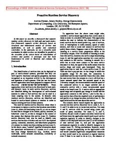
D.2.2 [Software EngineerFigure 1. Building robotic systems by composing reusable components with assured services.
Experimentation
Keywords Component Based Software Engineering, Model-Driven Engineering, Run-Time Model Usage, Service Robotics
1. Introduction Service robots are expected to fulfill complex tasks in unstructured everyday environments. Several robotic systems have already demonstrated promising capabilities like fetching beer from the refrigerator, playing pool, folding piles and performing interaction with humans. However, the implementation of those systems is still more of an art than a systematic engineering process. A systematic engineering process is essential to replace hand-crafted single-unit systems by systems composed out of matured and reusable components in order to decrease costs and time to market and to increase robustness. Typically, in robotics software there is no separation between the roles of the component builder and the system integrator. This is however necessary to enable reuse and establish a market for robotics software components as is already available for hardware components (e.g. sensors, robot platforms, manipulators). The vision is a component shelf (fig. 1) where component builders provide their components for reuse by system integrators. A system integrator reuses existing solutions in form of components having
Permission to make digital or hard copies of all or part of this work for personal or classroom use is granted without fee provided that copies are not made or distributed for profit or commercial advantage and that copies bear this notice and the full citation on the first page. To copy otherwise, to republish, to post on servers or to redistribute to lists, requires prior specific permission and/or a fee. GPCE’11, October 22–23, 2011, Portland, Oregon, USA. c 2011 ACM 978-1-4503-0689-8/11/10. . . $10.00 Copyright
73
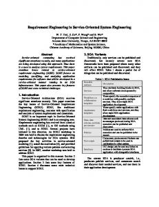
Figure 2. Models created at design-time are used and manipulated at run-time by the robot.
just a black-box view on them. That requires explication of parameters, properties and resource information of the components. Furthermore, advanced robots which operate in complex open environments have to cope with many different situations and contingencies. At run-time, the robot has to manage a huge amount of different execution variants that can never be foreseen and completely pre-programmed and can thus not be analysed and checked entirely at design-time. Managing the sheer variety of different execution variants requires to specify variation points at design-time and to bind them at run-time depending on situation and context. Therefore, the robot control mechanism, which orchestrates the components of the whole system, has to carry out such analysis and checks before setting the configuration. To be able to check whether the desired configuration and parametrization of the components is valid and reasonable, explicated information about components is required and needs to be taken into account.
An effective way to explicate such information and making it accessible for further processing is to rely on models [34]. They provide the ability to abstract and generalize from experience. Models are widely used in different domains since they are computational and can be transformed into different representations that can be manipulated by humans, as well as computers (fig. 2). We believe that making the step from code-driven to model-driven engineering in robotics is one of the basic necessities to achieve both (i) separation of roles and (ii) managing run-time decisions. This paper presents our approach of making the step towards model-centric robotic systems. The contributions are: • making the step from code-driven to model-driven development
of robotic systems by providing a robotics meta-model for robotic software components, • providing levels of abstraction which allow to transform the
models and generate code out of them, • using the models of the robotics software components at design-
time for simulation and analysis purposes, for example, relatime schedulability analysis of the relatime tasks, • bridging between design-time models of robotics software com-
ponents and their run-time representation, • using models at run-time to support the decision making pro-
cess of the robotic system by binding at run-time variation points that have been left-open purposefully at design-time, • an exhaustive real-world example where the approach is ap-
plied.
2. Motivation Software for autonomous robots is typically embedded, concurrent, real-time, distributed and data-intensive and must meet specific system requirements, such as safety, reliability, and fault tolerance. From this point of view robotic systems are similar to software systems in other domains, such as avionics, automotive, factory automation, telecommunication and even large scale information systems. The major differences that arise in robotics compared to other domains are not the huge amount of different sensors and actuators or the various hardware platforms. Instead, the huge amount of different system configurations changing even at run-time depending on current situation and context and a prioritized assignment of limited resources to activities are seen as robotic specific requirements. The resulting level of complexity goes beyond what is already handled in other domains. A complex robotic system can not be treated as a whole finalized system at design-time, for example, trying to analyse whether resource constraints are fulfilled. The idea presented in this paper is to use models for the entire life-cycle of the system. Such a model-centric view puts the models into the focus at both design-time and run-time. Models are, for example, used from the very beginning in the development of the software components, they support the deployment of the components to compose the robot system and they are finally used at run-time to support the decision making process. Models allow to explicate parameters and resource information to make these accessible by different tools and mechanisms and, for example, to ensure resource awareness. Models provide the ground for separation of roles as needed to make the step towards “able” industrial strength robots. They allow for components with explicitly stated properties. That is a prerequisite to compose systems out of reusable building blocks which provide assured and approved solutions. Models are a perfect mean to express the characteristics and structure of a CBSE approach [15]. In CBSE a complex system is split into independent units with well-formed interfaces. CBSE shifts the emphasis
74
in system-building from traditional requirement analysis, system design and implementation to composing software systems out of a mixture of reusable off-the-shelf and custom-built components. Although CBSE has been introduced into robotics, the missing abstraction of not using models to describe the components results in several drawbacks. Up to now, in most robotic systems fundamental properties of the software components are currently hidden in the source code of the components. In particular, Non-Functional Properties (NFPs) and Quality of Service (QoS) parameters are not explicated. Although such properties are considered being mandatory to compose complex systems out of reusable building blocks, they are not yet addressed in a systematic way by most robotic development processes. Consequently, these properties can not be taken into account neither at design-time, for example by analysis tools, nor at run-time by the robot control system. Taking a look into current robotic systems, reuse of existing solutions is mostly limited to the level of libraries and does not take place at the system integration level. In most robotic systems the integration and reuse of existing solutions is more like plumbing and thus error-prone and time consuming. Existing solutions are mostly bound to specific robotic middleware hypes, which typically change too fast to adapt existing solutions to the new technologies. Robotics so far circumvented the problem of a missing abstraction by not separating between the roles of the component builder and the system integrator. As long as both roles are carried out by the same persons, explicit descriptions which allow black-box reuse of existing solutions are not considered as essential. However, separation of roles is mandatory towards proper market structures and development of a robotics market. Composing complex robotic systems which are more mature and complex as current robots requires an established component market. Such a component market allows an integration of cutting edge solutions provided by different experts from different sites. Models allow to compete at the level of different implementations of components. They allow to collaborate at the model level of component interfaces and to collaborate at the system level. Especially the run-time model usage and exploitation of the explicated properties and information is mandatory to manage the huge amount of different situations and contingencies of open environments in order to achieve robust task execution. The best matching between current situation and proper robot behavior becomes overwhelming even for the most skilled robot engineer. The sheer variety of execution variants does at design-time neither allow an optimal solution nor an exhaustive assignment of proper reactions to situations. Instead, robustness requires situation and context dependent selection of available skills and system configurations at run-time. Thus, at design-time the developer specifies variation points and corridors in which the robot can make decisions and operate at run-time [31]. Thereby, appropriate properties and resource information are to be taken into account, also to support the decision making process at run-time. The relevance of making the step towards MDSD in robotics arises from multiple reasons and provides several benefits:
• abstracting from implementation details allows to express ap-
proved solutions and best-practices, as well as harmonizing and comparing different solutions independently of the implementation, • being able to provide different implementations of the agreed
abstract model allows competition at the level of implementations and collaboration at the system integration level, • expressing QoS parameters, like response times, for example,
to ensure collision avoidance,
Figure 3. The system engineer, as well as the robot reason on and manipulate the same models, but with different representations and views.
Figure 4. Model refinement by the example of software components covering design-time as well as run-time aspects.
• managing execution variants and system configurations at run-
builder, system integrator) and support run-time decisions based on design-time models. The S MART S OFT MDSD T OOLCHAIN (section 4) is one example of a tool covering design-time aspects of models of software components. S MART TCL (section 5) provides mechanisms for run-time model usage. The current approach is to extract information out of the models and provide them in the desired representation to perform reasoning, analysis and simulation. As the models coexist in parallel and are not harmonized, they can be inconsistent. At design-time consistency of representations is achieved by the transformations encoded in the toolchain to generate the representation. Transformation rules encode what partial information to take from which model to end up with a consistent representation for that specific partial view. At run-time S MART TCL action blocks represent valid queries and consistently aggregate the results in a precoded way for the particular context.
time by making the models accessible for the run-time system, • and finally, generating other models and artifacts, like source
code out of the models.
3. Model-Centric Robotic Systems Several models covering different aspects (software components, mechanics, simulation, analysis, planning) of the overall system coexist in parallel. The idea is not trying to harmonize the different models into one uniform representation. Rather, each model can have its specific representation according to the used tools (CHEDDAR [8], OpenRAVE [9], Gazebo [11], Metric-FF [16], etc.). This ensures that different and already existing tools and mechanisms can be used which depend on their proprietary model format. The model pool (fig. 3) can be seen as a container for the different heterogeneous models providing references to the models and maintaining meta information. It is a virtual construct to bundle the different models. Several models which are created at design-time by the developer are used at run-time by the robot. Thus, both the system engineer and the robot reason on the parameters, constraints, properties and other information explicated in the same models. However, they access them through different representations. Knowledge of how to transform models between the different representations and which partial information has to be taken into account, what representation is required and how results can be incorporated back is encoded in the tools (design-time) and in the action-plots (run-time). To prevent inconsistencies between the different models, modifications are just carried out in the original model and not in the representations. During the whole life-cycle the models are refined step by step until they finally get executable. The models comprise variation points which are bound during the development phase. Some variation points are bound by the component builder, while others are bound by the system integrator. The models also comprise variation points that are just bound during operation of the robot after specific context and situation dependent information is available. This way, variation points support separation of roles (e.g. component
75
4. The S MART S OFT T OOLCHAIN: Making the step towards MDSD in Robotics This section illustrates how we made the step towards MDSD and introduces our S MART S OFT MDSD T OOLCHAIN. The toolchain is based on the Eclipse Modeling Project (EMP) [10]. It is available for download on Sourceforge (http://smart-robotics. sf.net). 4.1 Identifying Stable Structures Separating the roles of the component builder, system integrator and the robot requires to identify, specify and explicate stable structures as well as variation points each role can rely on. These stable structures and variation points build the ground for a modelbased representation. Representing the structure of the component as meta-model enforces compliance of components with the metamodel via a MDSD-toolchain. We identified the component hull as the key structure to address the above challenges. A component hull composed out of stable elements allows a component builder to provide his solutions with guarantee for system level conformance. At the same time it gives him as much freedom as possible to integrate his business logic inside the compo-
Figure 5. Excerpt of the S MART MARS Meta-Model.
76
patterns
Table 1. The set of patterns and services of S MART MARS. Pattern Description send one-way communication query two-way request push newest 1-to-n distribution push timed 1-to-n distribution event asynchronous notification param component configuration state activate/deactivate component services wiring dynamic component wiring diagnose introspection of components
services
nent. The elements allow to explicate relevant information to ensure a black box view on the software components. The system integrator can then rely on the description of the component hulls to compose a system out of reusable blocks without inspecting the source files of each component. Since a component hull links the inner view and the outer view of a component, it has at least to comprise elements to explicate the communication ports and required resources (tasks, hardware dependencies), as well as access to component configurations (states, parameters). Figure 4 illustrates how the different roles refine the model of the software components. The component builder creates a model which defines the provided/required services of the component, parameters and properties as well as constraints. First model refinements are performed and the model is enriched with the specifics of its purpose. The SmartLaserServer, for example, provides access to a laser range finder. The component contains two service ports: one to push the latest laser scan to subscribed clients and the other one to switch the component on and off. Furthermore, the model defines the constraints, that the user-code (business logic) of the component contains C++/Linux specific parts and that the component requires one serial port (RS232). The system integrator picks the components out of the component shelf and deploys them onto the target system. The target system is specified by a platform description model (PDM) including information on the used processor type, provided hardware interfaces, the operating system and selected implementation of the S MART S OFT framework. In this phase further variation points are bound. Constraints are checked, hardware requirements are matched with the target platform and PDM specific refinements on the model are performed. Such analysis, checks and simulations are based on the model of the components and their deployment. At run-time the information explicated in the model is used to support the decision making process. The robot control system reasons and manipulates the model and reflects the adaptations in the models. The current configuration and state of the component is reflected in the run-time model representation. Using monitoring mechanisms, anomalies are detected and reported to the run-time system. The mechanisms that the robot uses to reason on the models might require specific representations depending on the mechanism. Therefore, the robot is able to transform between different representations at run-time.
4.2 The S MART MARS Meta-Model Identifying stable structures lead to our component model which we express as the S MART MARS (Modeling and Analysis of Robotic Systems) meta-model (fig. 5). S MART MARS is independent of the modeling technology (eCore, UML Profiles). In the current version of our toolchain we implemented it as a UML Profile using Papyrus UML. That gives us a handy way to provide a graphical representation of the meta-model. The instantiation of the S MART MARS meta-model is the S MART S OFT robotics framework. S MART S OFT is independent of the implementation technology (middleware, programming language, operating system) and scales from 8-bit microcontrollers up to large scale systems [30]. Two open-source reference implementations are available. The first implementation is based on CORBA (ACE/TAO) and the second one on ACE [32] only. The communication ports to handle inter-component communication are limited to a well defined set of services (table 1) with precisely defined semantics. The services are based on strictly enforced interaction patterns and are customized by the communication objects they transfer (e.g. laserscan, map). For user convenience further pre-configured services are provided (e.g. wiring, state) [29]. The services describe the outer view of a component, independent of its internal implementation. They decouple the sphere of influence and thus partition the overall complexity of the system. Internal characteristics can never span across components. The services provide stable interfaces towards the user code inside of the component and towards the other components independent of the underlying middleware structure. The interfaces can be used
Fatal
User Space
Alive Shutdown
Monitoring
Communication patterns
component lifecycle Init
PIM
State
Fatal
meta−information for user−code e.g. platform constraints −> runs only on QNX −> runs only on RTAI−Linux component lifecycle Init
State
Fatal
Alive
User Space
Alive
Event
Monitoring
stable interface (framework internal) to middleware and operating system
...
Middleware
OS
User Space
component lifecycle Init
Send State Query
Fatal
User Space
Alive
component lifecycle Init
Send State Query
Shutdown
...
Threads / Mutex / Timer Interface Execution Environment Linux / RTAI−Linux CORBA
...
Fatal
User Space
Alive Shutdown
Event Monitoring
stable interface towards other components
Threads / Mutex / Timer Interface Execution Environment
Shutdown
Diagnose
Send Query
Shutdown
Diagnose
PSM
stable interface towards user−code inside component
component lifecycle Init
Event Diagnose
Monitoring
Diagnose
...
Threads / Mutex / Timer Interface Execution Environment ACE Linux / RTAI−Linux
Send Query Event
Monitoring
...
Threads / Mutex / Timer Interface Execution Environment ACE Windows
... ACE QNX
interoperable
Figure 6. Middleware independence: user-code block (top-left) can be reused within different implementations of S MART S OFT . in completely different access modalities as they are not only forwarding method calls but are standalone entities. The query pattern, for example, provides both synchronous and asynchronous access modalities at the client side and a handler based interface at the server side. Interaction patterns are annotated with QoS parameters (e.g. cycle times for push timed pattern, timeouts for query and event pattern). This allows to build loosely coupled components which follow the principle of local responsibility. The set of interaction patterns covers request/response and publish/subscribe communication as well as asynchronous notification. Dynamic reconfiguration of the components at run-time is supported by a param service to send name-value pairs to the components, a state service to activate/deactivate different behaviors of a component and dynamic wiring to change the connections between the components. The state service is used by a component to manage transitions between service activations, to support housekeeping activities (entry/exit actions) and to hide details of private state relationships (appears as stateless interface to the outside). Inside of the components, the state service provides a state automaton with a generic and an individual part. The generic part provides a standardized life-cycle automaton for each component including the states: Init, Alive, Shutdown and FatalError. The individual part allows the component developer to add a component specific automaton as an extension into the Alive state of the generic automaton. [18] Dynamic wiring is the basis for making both the control flow and the data flow configurable. This is required for situated and task dependent composition of skills to behaviors. The wiring service supports dynamic wiring of component services from outside (and inside) a component.It allows to connect service requesters to service providers dynamically at run time. A service requester is connected only to a compatible service provider (same pattern and communication object). Disconnecting a service requester automatically performs all housekeeping activities inside an interaction pattern to sort out not yet answered and pending calls, for example, by iterating through the affected state automatons (inside interaction patterns) and thus properly unblocking method calls that otherwise would never return. For example, the wiring mechanism already properly sorts out effects of a server being destroyed while clients are in the process of connecting to it. Of course, this relieves a component builder from a huge source of potential pitfalls. Monitoring [18] provides a black box in a component to store different types of information from a component and to provide
77
this information as a generic service (diagnose service) to the outside of a component. This enables a system engineer, as well as the robot system itself, to gain insight into running components for the purpose of debugging, testing and monitoring. The information model of monitoring is based on profiles. Profiles allow to define different sources of information, individually in each component. Other components in a running system, as well as development tools, can use the diagnose service to request for particular information, which is currently of interest for monitoring. 4.3 Component Builder View on the Development of Components The major steps to develop a S MART S OFT component are depicted in fig. 6. The component builder develops the component in a platform independent representation using the meta-elements provided by the S MART MARS meta-model. He focuses on the definition of the component hull – without any implementation details in mind. The component hull provides both a stable interface towards the user-code (inner view of component) and a stable interface towards the other components (outer view of component). These stable interfaces allow to reuse the user-code block (fig. 6 top-left) independent of the binding to a specific implementation of the S MART S OFT concepts (CORBA, ACE, Shared-Memory, etc.). Due to the stable interface towards the user-code, algorithms and libraries can be integrated independent of any middleware structures. The integration is assisted and guided by the toolchain (e.g. oAW recipes). Tags on the user-code block are used to indicate constraints (e.g. runs only on RTAI-Linux). The stable interface towards the other components ensures replacement and rearrangement of components. 4.4 Model Transformation and Code Generation The model transformation and code generation steps are implemented using Xpand and Xtend from the Eclipse Modeling Project. The transformation into the PSM is completely hidden from the component builder. For the component builder it looks like a onestep transformation from the PIM into the PSI. Taking a look behind the scenes the PIM is transformed into a PSM and afterwards the PSI is generated out of the PSM. The PSI is generated against the S MART S OFT library. The user code is protected from modifications made by the code generator due to the generation gap pattern [36] which is based on inheritance.
SchedPolicyKind
SmartTask schedPolicy : SchedPolicyKind isRealtime : Boolean isPeriodic : Boolean priority : Integer timeUnit : TimeUnitType period : Integer wcet : Integer
PIM
isRealtime == false
isRealtime == true
SmartCorbaTask
RTAITask
PSM
schedPolicy : SchedPolicyKind isPeriodic : Boolean priority : Integer period : Integer
SmartCorbaTimer period : Integer
mutex [1]
SmartCorbaMutex
condMutex [0..1]
Figure 7. The transformation of the PIM and the PSM by means of the SmartTask meta-element. SmartMARS
PIM PSM
ACE/SmartSoft Corba/SmartSoft C++
User Code stable interface generated code
PSI
SmartSoft library
...
JMI/SmartSoft
...
Java
...
gen.
User Code generated code
U.C. gen.
lib.
SmartSoft lib.
lib.
C++
C++
User Code generated code
U.C.
SmartSoft library
1a
RTAITask
1b
PeriodicTask
≪class≫ Task1 User-Code 2
SmartTask pthread
SmartSoft lib. ACE Task ... Win32Thread
Figure 9. Gaps between desired (stable S MART S OFT interface) and provided functionality (library) can be closed by the transformation steps (1) or by extending the library (2).
schedPolicy : SchedPolicyKind isPeriodic : Boolean priority : Integer period : Integer wcet : Integer
SmartCorbaCondMutex
isPeriodic == true
M2M / ≪class≫ Task1Core M2T ... 1
PSM
FIFO round−robin sporadic
timer [0..1]
Generation Gap Pattern ≪model≫ Task1 ...
Figure 8. Generating different PSIs. Figure 7 shows the transformation of the PIM and the PSM by the example of the SmartTask meta-element and the CORBA (ACE/TAO) based PSM. The SmartTask (PIM) comprises several parameters which are necessary to describe the task behavior and its characteristics independent of the implementation. Depending on the attribute isRealtime and the capabilities of the target platform (PDM) the SmartTask is either mapped onto an RTAITask or a non-realtime SmartCorbaTask1 . If hard realtime capabilities are required and are not offered by the target platform, the toolchain reports this missing property. To perform realtime schedulability tests, the attributes wcet and period of the RTAITasks can be forwarded to appropriate analysis tools. In case the attributes specify a non-realtime, periodic SmartTask, the toolchain extends the PSM by the elements needed to emulate periodic tasks (as this feature is not covered by standard tasks). In each case the user integrates his algorithms and libraries into the stable interface provided by the SmartTask (user view) independent of the hidden internal mapping of the SmartTask (generated code). Figure 8 illustrates how different implementations based on different middleware technologies are managed. The PSI consists of the S MART S OFT library, the generated code and the user code. To be able to reuse a user-code block within different variants of S MART S OFT , the stable interface of the user-code block needs to match with the interface generated by the transformation steps. This interface of the target platform is provided by the S MARTS OFT library and the generated code. It ensures that, for example, 1 Element
names including Corba, indicate that the element belongs to the CORBA specific PSM.
78
a user-code block with C++ binding can be re-used within different C++ based S MART S OFT implementations. These different implementations follow the exact same syntax and semantic. However, small gaps (if existent) between the different implementations can be closed by generating appropriate code fragments. For example, one implementation supports periodic tasks directly, while another one requires additional code fragments in the generated part of the PSI (cf. fig. 7). Such gaps can be closed at least by the two ways illustrated in figure 9 by the example of the S MART TASK: (1) Features, which are not covered by the library are added by the transformation steps into the generated code. This is either done by the M2M transformation as illustrated above by the example of making a standard task periodic, or directly in the M2T transformation step by providing suitable templates. This option has the advantage, that the library has not to be modified. (2) The missing functionality can also be integrated into the library. This option eases the transformation steps, but requires dedicated access for the framework/toolchain builder to the library. In our approach we provide the major part of the functionality within the library and thus keep the PSM very thin. Only small gaps are closed using the described option (1). Furthermore, the deployment model and the models of the components can be transformed into analysis models. One example is the transformation into a CHEDDAR [8] specific analysis model to perform hard realtime schedulability tests. Therefore, the hard realtime tasks of the deployed components are taken into account. The parameters of the tasks which are explicated in the models are transformed into a representation which is specific to CHEDDAR. These transformation rules are encoded in the toolchain.
5. Exploiting Models at Run-Time This section gives insights into the robot control system and how to use models at run-time. To support the decision making process, analysis tools are required for evaluation and balancing of different alternative plans or to check whether the desired system configuration is valid, before modifying the configuration of the robot. The concrete binding of variation points which were left open at design-time can be analysed at run-time to be able to decide for the most appropriate execution variant depending on current situation and context. In the same manner as analysis tools, simulators (e.g. physics simulators) are used to check pending execution steps with different parametrisation before the robot executes them. The whole system from a CBSE point-of-view is illustrated in figure 10. To manage the huge amount of execution variants, a sequencing mechanism is used which supports the exploitation of models at run-time and thus allows to take advantage from the explicated parameters and properties. The task sequencing mechanisms are wrapped by a component hull and use thus the same communication infrastructure as the other components (skill components). The communication mechanisms between the sequencer
event−driven task execution orchestration of the components ...
control loops, planning, continuous processing service oriented components
...
skill components pl an ne m r ap pe r L AM A M et ric −F F l as er ba se O R pe AV n E
Sequencer (SmartTCL)
symbolic /subsymbolic mechanisms
Figure 10. The sequencer coordinates the robot by orchestrating the components.
Figure 11. left: S MART TCL meta-model. right: The S MART TCL task-tree. (a) run-time decisions between execution variants; (b) contingency handling (rules) by replacing parts of the task-tree.
and the skill components are: (i) param to send commands and parameters by name-value pairs, (ii) state to activate/deactivate component internal behaviors, (iii) query to request information and (iv) wiring to change the data-flow between the components. The event mechanism, as well as the diagnose service are used by the skill components to signal notifications. The components have to follow the paradigm of local responsibility and cognizant failures [24], stating that systems should be designed to detect failures when they occur. Failures that can be handled locally inside of the component have to be handled there. Failures which can not be resolved inside the component have to be signaled (events) to the sequencer which provides appropriate recovery strategies. Due to the stable interfaces of the component, the different events which could be signaled are known at design-time and appropriate recovery strategies can be provided. The sequencer has the control over the whole system. It performs dynamic on-line reconfigurations of the software components of the robot system. It parametrizes the components and switches different behaviors of the components on and off. The sequencer is the place to store procedural knowledge on how to configure skills to behaviors, when to use a symbolic planner or analysis tool and what kind of action plots are suitable to achieve certain goals. It bridges between continuous processing (motion control, path planning) and event driven task execution (discrete states). The sequencer directly interacts with the Knowledge Base (KB) to reflect, for example, the current world state, information about resources and the configuration of the software components. Furthermore, the KB contains information about the world, like object properties, persons and locations. 5.1 Bridging between Design-Time and Run-Time Models of Software Components Software components are the major building blocks in almost every robotic system. They contain relevant parameters, properties and resource information which are required to be taken into account at run-time to support the decision-making process. This information can be used to perform analysis, validation, simulation and planning of different execution variants. To take advantage of these models at run-time they are integrated into the robot control system. The UML/XMI representation is transformed at design-time by the toolchain into an ontology representation of the used KB system (e.g. Knowledge Machine, PowerLOOM). Thus a mapping of the meta-elements into the ontology concepts takes place. For example, in the meta-model a task is expressed by the meta-element SmartTask with attributes, like period, isPeriodic, wcet, and priority. In the ontology representation of Knowledge Machine the SmartTask is represented by the class Task, the attributes of the SmartTask are transformed to slots and the composition between the SmartComponent and the SmartTask is expressed by a relation. In the deployment phase, the software components (executables), parameter files and the KB representation is loaded onto the
79
computer of the robot. At run-time, this ontology representation can then be accessed by the robot to reason on the parameters, for example, to check the resources, reflect the current state and activation of the components and the wiring between the components. This knowledge about the robot system allows for appropriate, approved and resource aware balancing between execution variants. 5.2 The Sequencer: S MART TCL The sequencer in the system is implemented with S MART TCL [35]. The S MART TCL meta-model is illustrated in figure 11 on the left. It supports hierarchical task decomposition and situationdriven task execution. At run-time a task-tree is dynamically created and modified depending on situation and context (fig. 11 right). S MART TCL comprises three constructs: (i) Task Coordination Blocks (TCB), (ii) rules for contingency handling and (iii) event-handler which are associated to events. Each construct comprises an action plot which contains the business logic. The nodes of the task tree are instances of Task Coordination Blocks (TCB). Each block comprises the action plot it executes and optionally a plan including references to other nodes (children). The TCBs are stored in the KB of the robot and instantiated at run-time just before execution. The concrete block is selected at run-time based on the precondition clause (fig. 11 right (a)). In S MART TCL the reaction to failures is defined by rules. Whenever a TCB has finished, the return message is checked by the parent node and matched against the rules which are stored in the KB. The action plot of the matched rule is executed by the parent node, for example, to recover from a failure (fig. 11 right (b)). Therefore, the action plots can delete, replace or add nodes in the task tree or send commands and parameters to the components in the system. Each block is responsible to do its best trying to achieve the expected goal and state an error message (return message) if it fails. In such a situation only the parent which has spawned the child node “knows” about the purpose of the node in a wider context and can thus react to the failure. That hierarchical structure of responsibilities ensures a clear separation of concerns. The rules can be used to define a corridor in which the task execution and management of the nodes in the task tree have to remain. In S MART TCL a task-tree is specified at design-time. Several variation points are left open and bound at run-time: (i) selection for the exact TCB to execute (ii) the further expansion of a node is bound by a certain mechanism. An example for (ii) is the binding of variation points using a symbolic task planner (e.g. Metric-FF). At design-time just the action plot of the node calling the planner is specified. The action plot has encoded which partial information to extract out of the run-time model, how to transform it into the appropriate model representation of the symbolic task planner (e.g. PDDL [12]) and how to import the generated plan back into the S MART TCL task-tree. As the generated plan is transformed into nodes of the tree, the execution is performed by the S MART TCL
Figure 12. The clean-up scenario. (1) Kate approaches the table; (2/3) Kate stacks objects into each other; (4) Kate throws cups into the kitchen sink.
run-time system. Thus the mechanism of the rules is used to define how plan deviations are handled. Either the plan can be repaired locally, or a complete new plan has to be generated. This situation dependent knowledge is encoded in the action-plot of the rules.
6. Example The work presented in this paper has been used to build and run several real-world scenarios, including the participation at the RoboCup@Home challenge. Our robot “Kate” can, for example, follow persons, deliver drinks, recognize persons and objects and interact with humans by gestures and speech. Different scenarios are built by composing already existing components (e.g. mapping, path planning, collision avoidance, laser ranger, robot-base, etc.) taken from the component shelf. The S MART TCL sequencing mechanisms are also provided by a component taken from the shelf. Inside of this component the S MART TCL model is refined to specify the desired robot behavior by adding new ones as well as reusing already existing ones. Thus, reuse takes place at the level of components as well as behaviors. In the clean-up scenario 2 (fig. 12) the robot approaches a table, recognizes the objects which are placed on the table and cleans them either by throwing them into the trash bin or into the kitchen sink. The objects include cups, beverage cans and different types of crisp cans. The cups could be stacked into each other and have to be thrown into the kitchen sink. Beverage cans can be stacked into crisp cans and have to be thrown into the trash bin. Depending on the type of crisp can, one or two beverage cans can be stacked into. Furthermore, after throwing some of the objects into the correct destination the robot has to decide whether to drive back to the table to clean up the remaining objects (if existing) or to drive to the operator and announce the result of the cleaning task. The robot reports whether all objects on the table could be cleaned up or if any problems occurred, how many objects are still left. Already with just a few different objects to stack into each other and simple constraints on how to handle the objects, the amount of different execution variants to clean up a table gets overwhelming and can hardly be pre-program in fixed sequences of execution steps. Furthermore, contingencies, like no object could be found on the table, an object could not be grasped, no IK solution could be found to grasp an object and problems in the path-planning are handled. Almost every single step of such a sequence can fail for different reasons and requires appropriate recovery strategies. To bind the left open variation point (how to stack the objects) the node which 2 http://youtu.be/xtLK-655v7k
80
is responsible to stack the recognized objects calls the symbolic task planner Metric-FF. The knowledge about recognized objects and the properties how to handle them are extracted from the KB, and transformed into a PDDL model representation, which is forwarded to the planner. The generated plan is then imported into the task-tree as child nodes. Several failures in the plan execution are handled – either the failure can be recovered locally in the tasktree or the plan has to be discarded and a complete new plan has to be generated. This recovery and re-planning strategies are managed by the parent node with the help of the rules and defines the corridor in which the generated plan has to remain. To further improve the robustness of the overall system the robot control system is additionally able to execute internal run-time diagnoses and to react on anomalies in the system. For example, a broken connection to the laser range finder device in the SmartLaserServer component is detected by monitoring and the sequencer can react on this failure and stop the robot navigation component and try to recover from that failure. Resources are managed by activating/ deactivating components (speech interaction, person tracking, localization, navigation, object recognition, OpenRAVE) depending on the current situation and task which is performed. For example to manipulate objects on the table, components for navigation are switched off to safe resources that can then be fully accessed by OpenRAVE for the trajectory planning of the manipulator. This management of the resources is performed by S MART TCL taking information explicated in the models into account and reflecting modifications in their usage.
7. Gained Experience In this section we describe the practical experience we gained by implementing the S MART S OFT MDSD T OOLCHAIN. The following topics have been identified as missing in the current state, but are needed in our robotics use cases: (1) Support for different roles (component builder, system integrator, robot) to refine the model are required to provide a clear separation between the roles. Each role should have different access policies individual for the model elements to specify and modify them. To illustrate: a component builder should, for example, be able to specify a range for a parameter, the system integrator then chooses a default value in this range and finally the robot modifies the parameter in the specified range according to the situation at run-time. The access policies should cover use cases like: (i) The component builder sets a value for a parameter that can not be changed either by the system integrator nor by the robot. (ii) The component builder models a parameter without specifying a default value. The parameter has to be bound by the system integrator, but can not be modified by the robot. (2) Instances of components including dedicated parametrizations per instance are required by the system integrator to customize components individually for the use case and to model multiple executions of one component. For example, a robot with two laser scanners (front, rear) requires two instances of the same component. Each instance needs its individual parametrization, like different serial ports and different position offset values. The component builder should be able to specify which properties have to be bound by the system integrator during the deployment step. Instances and their individual parametrization is not adequately supported, for example, by UML and its extension mechanism UML Profiles. (3) Mechanisms to express relations between model elements and their parameters should be included in the models. For example, we need to express that modifying the property ”cycle time” of the navigation component directly changes the property ”maximum allowed velocity” (e.g. linear relation). This is required that the system integrator can modify parameters in the model without knowing about their exact influence on other parameters. The rela-
tions between the model elements and their parameters should be modeled by the component builder. (4) Binding and unbinding of model parameters. Modifying a specific parameter in the model may induce that depending parameters get unbound and have to be bound with respect to the new configuration. For example, changing the processor type invalidates all hard realtime worst-case execution times (wcet).
8. Related Work In recent years, the Model-Driven Engineering (MDE) paradigm, has successfully been introduced in domains where systems are also highly complex, need a multi-disciplinary development approach, and require high reliability and robustness, such as: embedded systems, automotive and home automation. For example, the Artist2 Network of Excellence on Embedded Systems Design [3] addresses highly relevant topics concerning realtime components and realtime execution platforms. The automotive industry is trying to establish the AUTOSAR standard [4] for software components and model-driven design of such components. AUTOSAR will provide a software infrastructure for automotive systems, based on standardized interfaces. Related to AUTOSAR, the ongoing RT-Describe project [28] addresses resource aspects. To adapt the system during run-time, RT-Describe relies on self-description of the components. Software components shall be enabled to autonomously reconfigure themselves, for example, by deactivating functions that are currently not needed. The OMG MARTE [25] activity provides a standard for modeling and analysis of realtime and embedded systems. They provide a huge number of non-functional properties (NFPs) to describe both the internals and externals of the system. Mappings to analysis models (CHEDDAR, RapidRMA) are available to perform scheduling analysis of MARTE models. This part of the MARTE profile is of interest to the robotics community. In the MOST [23] project they are marrying ontology and software technology by integrating ontologies into MDSD. This is of interest for our work, as we are also dealing with both worlds. However, our focus is to reason on the models to support the decision making process of the robot at run-time. The DiVA project [22] leverages models@runtime to support the design and execution of Dynamic Software Product Lines (DSPL) [14]. At design-time four views of a DSPL are described and used at run-time to drive the dynamic adaptation process. In [17], DiVA is used to address adaptations in robotics. The authors provide a case study to gain experience on advantages and drawbacks of applying DiVA to robotic systems. In their approach DiVA is used to adapt high-level models at run-time by the robot itself. An introduction into robotics component-based software engineering (CBSE) can be found in [6, 7]. Several important design principles and implementation guidelines that enable the development of reusable and maintainable software building-blocks are motivated in detail. In robotics, models are currently mainly used at design-time to model single aspects like simulation, control and algorithms [20] [21]. For example, in ROS [27] the Unified Robot Description Format (URDF) is used to specify the model of the robot. This model can be used in Gazebo [11] (simulation) as well as in Rviz [27] (visualisation). Furthermore, models are used to define robotic software components. This allows to abstract from implementation and middleware details. The Object Management Group (OMG), for example, has standardized a robotics component model [26]. Based on that standard several implementations [2, 13, 33] were developed. In [1] the 3-View Component MetaModel (V3CMM) is proposed to model component based systems independent of the execution platform. The GenoM3 [19] project tries to harmonize different robotic frameworks by providing a generic component model and component templates that are spe-
81
cific for each framework. In these approaches they managed to identify stable structures and to provide them in the form of models. Thus, they can be re-used and compared. In the above mentioned approaches, models are used for documentation purposes, abstracting from implementation details, describing the components in an abstract representation and generating source code out of the models. These are already promising examples for what models can be used for, although they just cover small aspects. In comparison to those approaches, we additionally use the models to define variation points at design-time and bind them at run-time. Therefore, we take advantage of the parameters, properties and resource information which are made accessible in the models [31].
9. Conclusions and Future Work In this paper we present the current state of our work to make the step towards model-driven engineering in robotics. We present first results of our overall goal to shift the emphasis towards a model-centric view on the whole system. Making the step from code-driven to model-driven engineering provides the ground for a component market, based on models and to provide a component shelf as described in this paper. Models encourage to separate between the roles of the component builder, system integrator and the robot. They allow to collaborate at the modelling level, and to compete at the level of implementations. That provides the freedom to choose whatever implementation technology is most adequate in a certain target domain. Furthermore, the at design-time in the models explicated information is used at run-time by the robot to support the decision making process. This is of importance to manage the huge amount of different situations and contingencies occurring in open real-world environments. The presented work on the S MART S OFT MDSD T OOLCHAIN provides promising results and reflects the state of the art of applying MDSD to the service robotics domain. The toolchain has successfully been used to build several robotic scenarios. The MDSD approach helped us to come up with running systems and to successfully master their overall complexity. Mastering the component hull with the help of a MDSD toolchain significantly improved the learning curve of developing proper robotics components. The component builder is guided by the toolchain and compliance with our component model is achieved by the meta-model. Students writing their thesis or doing an intern in our lab are able to build components without giving them to much explanations. We agree on the component hull and define the services the component should offer and they are free to implement the business logic according to their needs. The remaining component required to develop a whole scenario can be taken form our component shelf. Our robocup team, for example, which is driven by students from our university could reuse several of the already existing components without going through the source code of the components. A fixed component hull allows to implement components based on that hull but providing a different business logic inside the component. Consequently they can easily be replaced and thus compared against each other. Providing stable structures in the form of meta-models proved to abstract from implementation details. The stable structures we identified and provide as our S MART S OFT component model already demonstrate that different implementations can be provided. We have developed two reference implementations, one based on ACE (messaging) and the other one on CORBA (ACE/TAO). Furthermore, [5] is working on a DDS based implementation of S MART S OFT . In our toolchain the transformation currently relies on the two steps (i) PIM to PSM (M2M) and (ii) PSM to PSI (M2T). This strict two step transformation enforces a too narrow transformation workflow. Adding platform information is an important, but not
the only step. The focus should be shifted towards a stepwise refinement of the model without any fixed number of steps. In such a refinement workflow, the target platform information, as well as results gained from analysis or simulations are incorporated step by step whenever new information is available or already available information has changed. Future work will deal with model refinement and its integrations into our toolchain. We will further extend the usage of the very same models during system development, deployment and at run-time. Especially the further integration of run-time simulation coordinated by the sequencer will be next steps for that the current results already provide a suitable foundation.
Acknowledgments This work has been conducted within the ZAFH Servicerobotik (http://www.servicerobotik.de/). The authors gratefully acknowledge the research grants of state of Baden-W¨urttemberg and the European Union. We thank Dennis Stampfer for his extraordinary support in implementing the S MART S OFT MDSD T OOLCHAIN. We greatfully acknowledge the work of Jonas Brich, Siegfried Hochdorfer, Matthias Lutz and Manuel Wopfner for their contributions to the clean-up scenario described in the example section.
References ´ [1] D. Alonso, C. Vicente-Chicote, F. Ortiz, J. Pastor, and Alvarez B. V3CMM: a 3-View Component Meta-Model for Model-Driven Robotic Software Development. Journal of Software Engineering for Robotics (JOSER), 2009. [2] N. Ando, T. Suehiro, K. Kitagaki, T. Kotoku, and W. Yoon. RTComponent Object Model in RTMiddleware - Distributed Component Middleware for RT (Robot Technology). In IEEE Int. Symposium on Computational Intelligence in Robotics and Automation (CIRA), 2005. [3] ARTIST. Network of excellence on embedded system design. http: //www.artist-embedded.org/, visited on May 15th 2011. [4] AUTOSAR. Automotive open system architecture. http://www. autosar.org/, visited on May 15th 2011. [5] J. Bandera, A. Romero-Garces, and J. Martinez. Towards a DDSbased Platform Specific Model for Robotics. In 6th Int. Workshop on Software Development and Integration in Robotics (SDIR VI) affilated with ICRA 2011, Shanghai, China, 2011. [6] D. Brugali and P. Scandurra. Component-Based Robotic Engineering (Part I). IEEE Robotics & Automation Magazine, 16(4):84–96, Dezember 2009. [7] D. Brugali and A. Shakhimardanov. Component-Based Robotic Engineering (Part II). IEEE Robotics & Automation Magazine, 17(1): 100–112, March 2010. [8] Cheddar. a free real time scheduling analyzer, http://beru. univ-brest.fr/~ singhoff/cheddar/, May 15th 2011. [9] R. Diankov. Automated Construction of Robotic Manipulation Programs. PhD thesis, Carnegie Mellon University, Robotics Institute, August 2010. [10] Eclipse Modeling Project. http://www.eclipse.org/modeling/, February 15th 2011. [11] Gazebo. Gazebo - 3D multiple robot simulator with dynamics, 2006. http://playerstage.sourceforge.net/gazebo/ gazebo.html, visited on May 15th 2011. [12] M. Ghallab, C. K. Isi, S. Penberthy, D. E. Smith, Y. Sun, and D. Weld. PDDL - The Planning Domain Definition Language. Technical report, CVC TR-98-003/DCS TR-1165, Yale Center for Computational Vision and Control, 1998. [13] Gostai RTC. http://www.gostai.com/products/rtc/, May 15th 2011. [14] S. Hallsteinsen, M. Hinchey, S. Park, and K. Schmid. Dynamic Software Product Lines. IEEE Computer, 41(4):93–95, April 2008. ISSN 0018-9162.
82
[15] G. T. Heineman and W. T. Councill. Component-Based Software Engineering: Putting the Pieces Together. Addison-Wesley Professional, June 2001. ISBN 0201704854. [16] J. Hoffmann and B. Nebel. The FF Planning System: Fast Plan Generation Through Heuristic Search. Journal of Artificial Intelligence Research, 14:253–302, 2001. [17] J. F. Ingl´es-Romero, C. Vicente-Chicote, B. Morin, and B. Olivier. Using Models@Runtime for Designing Adaptive Robotics Software: an Experience Report. In 1st Int. workshop on Model Based Engineering for Robotics: RoSym’10 at (MODELS’10), Oslo, Norway, 2010. [18] A. Lotz, A. Steck, and C. Schlegel. Runtime Monitoring of Robotics Software Components: Increasing Robustness of Service Robotic Systems. In Int. Conf. on Advanced Robotics (ICAR), 2011. [19] A. Mallet, C. Pasteur, M. Herrb, S. Lemaignan, and F. Ingrand. GenoM3: Building middleware-independent robotic components. In IEEE Int. Conf. on Robotics and Automation (ICRA), 2010. [20] Matlab / Simulink. http://www.mathworks.com/, May 15th 2011. [21] MODELICA. http://www.modelica.org/, May 15th 2011. [22] B. Morin, O. Barais, J.-M. J´ez´equel, F. Fleurey, and A. Solberg. Models@Runtime to Support Dynamic Adaptation. IEEE Computer, pages 44–51, October 2009. [23] MOST. Marrying Ontology and Software Technology. http://www. most-project.eu, visited on May 15th 2011. [24] F. Noreils. Integrating error recovery in a mobile robot control system. In Int. Conf. on Robotics and Automation (ICRA), pages 396–401, 1990. [25] OMG MARTE. A UML Profile for MARTE: Modeling and Analysis of Real-Time Embedded systems, Beta 2, ptc/2008-06-08, June 2008. [26] OMG RTC. Robotic Technology Component (RTC) Specification 1.0, 2008. http://www.omg.org/spec/RTC, May 15th 2011. [27] M. Quigley, B. Gerkey, K. Conley, J. Faust, T. Foote, J. Leibs, E. Berger, R. Wheeler, and A. Ng. ROS: An open-source Robot Operating System. In ICRA Workshop on OSS, 2009. [28] RT-Describe. Iterative Design Process for Self-Describing Real Time Embedded Software Components, 2010. http://www. esk.fraunhofer.de/en/projects/RT-Describe.html, visited on May 15th 2011. [29] C. Schlegel. Communication Patterns as Key Towards ComponentBased Robotics. Int. Journal of Advanced Robotic Systems, 3(1):49 – 54, 2006. [30] C. Schlegel, T. Haßler, A. Lotz, and A. Steck. Robotic software systems: From code-driven to model-driven designs. In Int. Conf. on Advanced Robotics (ICAR), June 2009. [31] C. Schlegel, A. Steck, D. Brugali, and A. Knoll. Design Abstraction and Processes in Robotics: From Code-Driven to Model-Driven Engineering. In Int. Conf. on Simulation, Modeling and Programming for Autonomous Robots (SIMPAR), volume 6472 of LNCS, pages 324– 335. Springer, Darmstadt, Germany, 2010. [32] D. Schmidt. The ADAPTIVE Communication Environment. http: //www.cs.wustl.edu/~ schmidt/, visited on May 15th 2011. [33] B. Song, S. Jung, C. Jang, and S. Kim. An Introduction to Robot Component Model for OPRoS (Open Platform for Robotic Services). In Workshop Proceedings of SIMPAR, pages 592–603, 2008. [34] T. Stahl and M. V¨olter. Model-Driven Software Development: Technology, Engineering, Management. Wiley, Chichester, UK, 2006. ISBN 978-0-470-02570-3. [35] A. Steck and C. Schlegel. SmartTCL: An Execution Language for Conditional Reactive Task Execution in a Three Layer Architecture for Service Robots. In Int. Workshop on DYnamic languages for RObotic and Sensors systems (DYROS/SIMPAR), pages 274–277. Springer, Darmstadt, Germany, 2010. ISBN 978-3-00-032863-3. [36] J. Vlissides. Pattern Hatching – Generation Gap Pattern. http://researchweb.watson.ibm.com/designpatterns/ pubs/gg.html, visited on May 15th 2011.