the wire impedance become comparable to its resistive part. [1]. In this paper, we explore inductive coupling effects be- tween neighboring parallel wires using a ...
MODELING AND IMPLEMENTATION OF TWISTED DIFFERENTIAL ON-CHIP INTERCONNECTS FOR CROSSTALK NOISE REDUCTION ˙ Hatırnaz and Y. Leblebici I. Swiss Federal Institute of Technology (EPFL) Microelectronic Systems Laboratory (LSM) CH-1015 Lausanne, Switzerland Ilhan.Hatirnaz@epfl.ch, Yusuf.Leblebici@epfl.ch ABSTRACT A simple generic interconnect architecture is presented to allow effective cancellation of inductive and capacitive noise in high-speed on-chip interconnect lines. The approach is based on the principle of constructing periodically twisted differential line pairs for parallel interconnect segments in order to eliminate the mutual coupling influences. Detailed simulations show that the twisted-differential lines (TDL) provide high-speed and crosstalk-immnune interconnects, compared to single-ended and differential lines. 1. INTRODUCTION With continued scaling of device features and interconnect dimensions down to deep-sub-micron and nanometer range, interconnects are becoming the limiting factor for performance and reliability in many system-on-chip (SoC) designs. Since the overall chip dimensions continue to increase with increasing system complexity, interconnects especially the global connections between various system blocks on chip - tend to get longer. At the same time, wire width and wire separation continue to drop while their cross-sectional area is scaled down at a slower rate to prevent resistance values increase dramatically. This ongoing trend of controlling the RC delay, combined with the faster rise/fall times and longer wires, makes the inductive part of the wire impedance become comparable to its resistive part [1]. In this paper, we explore inductive coupling effects between neighboring parallel wires using a simple, physicallybased equivalent circuit model, and we propose simple generic interconnect architecture to reduce cross-talk noise due to capacitive and inductive coupling between the interconnects and to reduce the interconnect delay, as well. This approach could prove to be a very suitable solution for the design of long high-speed bus lines that link various system sub-blocks on chip, achieving very low, predictable delays and noise levels even at very high switching speeds.
������������;����������������,(((
Fig. 1. RLCM model of an interconnect segment, showing inductive and capacitive coupling between two parallel lines. 2. ON-CHIP INTERCONNECTS The classical approach for modelling on-chip interconnects is based on the assumption that the wire loads are mainly capacitive and lumped. In most cases, however, the load conditions imposed on the interconnection line are far from being simple. The line, itself a three-dimensional structure in metal (aluminium wires and tungsten vias), usually has a non-negligible resistance in addition to its capacitance. The (length/width) ratio of the wire usually dictates that the parameters are distributed, making the interconnect a true transmission line. Also, an interconnect is rarely isolated from other influences. In realistic conditions, the interconnection line is in very close proximity to a number of other lines, either on the same level or on different levels. The capacitive/inductive coupling and the signal interference between neighboring lines should also be taken into consideration for an accurate estimation of delay. In general, if the time of flight across the interconnection line (as determined by the speed of light) is much shorter than the signal rise/fall times, then the wire can be modelled as a capacitive load, or as a lumped or distributed RC
9������
,6&$6�����
network. If the interconnection lines are sufficiently long and the rise times of the signal waveforms are comparable to the time of flight across the line, then the inductance also becomes important, and the interconnection lines must be modelled as transmission lines. Figure 1 shows the simplified cross-section of two parallel interconnect lines, together with one segment of the distributed RLCM network that represents the resistive/capacitive/inductive loads as well as the capacitive and inductive coupling between the lines (also called the PEEC model, [2]). The inductive effects mainly manifest themselves as the overshooting and undershooting of the signal edges, switching noise due to Ldi/dt voltage drop, and the long-range coupling. However, most of the techniques which have been used in order to reduce noise on wires, like shielding, increasing metal-to-metal spacing and etc., are more suitable for countering capacitive effects. The capacitive cross-talk noise can be easily reduced by introducing a shield between the aggressor line and the victim line, because electric fields are terminated on the neighboring metallic nodes. However, the same is not necessarily true for the magnetic fields, which may extend well beyond the aggressor nodes. Therefore, the definition of the return path is very critical in determining the inductance of a wire. In the following, we demonstrate how the capacitive noise and the inductive noise can be suppressed significantly by applying a simple, repetitive interconnect pattern (structure) at the layout level.
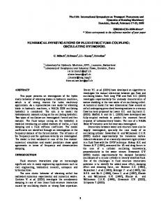
The benefits of using twisted lines on printed circuit boards (PCB) are already studied and well-known [5]. Twisted line interconnect architectures have been proposed earlier for on-chip connections as well [5][6], but the systematic application of this structure together with full-differential signaling has not been studied or analyzed yet. 4. ANALYSIS OF THE TDL STRUCTURE Now, assume that two adjacent differential signal lines are formed as shown in the Figure 2. In this figure, the length of lines between two twisting sections (twisting period) is assumed to be much larger than the distance between the differential pairs. In the TDL structure the complementary signals of the differential pair are routed parallel to each other until to the twisting point, where, one signal of the differential pair changes its track on the same metal level; whereas, the other signal goes one level down through a via, crosses below its complementary signal and switches back to the initial metal layer. Hence, the signals exchange their routing tracks. This twisting of signals is repeated at equal intervals. It should be noted that the neighboring differential pairs have to be routed so that their twisting points are offset relative to them, as shown in Figure 2. �
�
�
�
�
�
�
� �
�
�
�
�
�
�
�
�
�
�
�
DiffSignal1_H DiffSignal1_L �
�
�
�
�
�
�
�
�
�
�
�
�
�
�
�
�
�
�
�
� �
�
�
� �
� �
� �
� �
� �
� �
� �
�
� �
� �
� �
� �
�
� �
� �
�
� �
� �
�
� �
�
�
�
� � �
�
�
�
�
�
� �
� �
�
�
�
� �
� �
�
�
�
� �
3. INDUCTIVE COUPLING BASICS
�
�
�
�
�
DiffSignal2_H DiffSignal2_L
�
�
�
� �
�
�
�
�
�
� �
�
� �
�
�
� �
� �
�
�
�
� �
�
�
�
�
�
�
�
�
�
�
�
�
�
�
Our first assumption is that we use two parallel traces for each signal line; driven in true differential mode: while one of the input nodes of the line is making a low-to-high transition, its complementary input node is making a high-to-low transition. Clearly, it requires gates (or line drivers) with two complementary outputs and also, differential receivers. Using low-voltage swing differential signaling already offers a range of advantages: faster circuits, less crosstalk susceptibility, reduced power consumption and reduced electro-magnetic interference (EMI). All these benefits are mainly due to the fact that the differential driver needs to drive a load only to a few hundreds of millivolts, compared to a few volts depending on the technology used. Therefore, differential drivers are much smaller compared to singleended drivers, which results in smaller change of current in time, followed by significant reduction of inductive noise [3]. Still, the use of full differential signaling is not capable of eliminating the inductive crosstalk between lines. To allow a perfect cancellation of coupled magnetic and electric field components between two parallel adjacent lines, we consider using twisted differential line (TDL) [4].
�
�
�
� �
� �
�
Twisting Period
Fig. 2. Offset-twisted differential line arrangement at the layout level. As far as the crosstalk issues are concerned, one of the differential pairs can be imagined as the aggressor and the other one as the victim line. It can be easily proved that the amount of induced voltages on the victim line will cancel out each other for any two adjacent twisted sections. Also note that in the proposed arrangement (offset twisted differential line), there is no fundamental difference between the aggressor and the victim line - i.e., the roles are completely reversible, and the cancelling effect would be observed in that case, as well. Now, the phenomenon of inductive crosstalk noise cancellation can also be described by using the coupled PEEC models for the two differential lines. To simplify the view, only the partial inductance elements are shown. Each line segment is modeled by two equal partial inductances [2][3],
9������
as shown below in Figure 3. Note the current directions in each branch and the dots indicating the direction of inductive coupling.
Fig. 3. Lumped circuit element model of two TDL segments, showing only inductive elements for simplicity.
Fig. 4. The change of wire delay vs. wire length given for single-ended and differential lines.
Note that the polarity of the voltage induced by one inductor (L) on an adjacent inductor is determined by the relative location of the dots and by the current directions. At the same time, the magnitude of the induced voltage is determined by the amount of mutual inductance (M) between two adjacent line segments. It can be seen that the voltage induced by each partial inductor will be cancelled out by the voltage (same magnitude, reverse polarity) induced on the neighboring segment. Also note that this is true for all line segments (even for those located further apart) and not just the closest ones. Furthermore, it can be shown easily that the offset TDL structure is similarly effective for the cancellation of capacitive coupling between the adjacent line pairs.
The delay of the twisted-differential lines depend on a few parameters, which are the twisting period and the number of parallel vias used per layer change for twisting of signals. Therefore, the TDL delays of a 2mm long wire are given separately in Table 1. The segment length dictates the number of RLCM networks used to model the wire for one twisting period and only changes the granularity of our model. It is obvious from the table that for the same length of wire, there is a big change in delay depending on the twisting period and the number of vias (per layer change). The higher the twisting period, the smaller is the wire delay and the effect of the number of vias on the delay. As we shorten the twisting period, more twistings must be placed for routing the same length of wire, which results in a higher number of total vias and in a longer delay.
5. SIMULATION RESULTS To demonstrate the effectiveness of the proposed approach, both delay and crosstalk simulations were made on the TDL segments, also, on the differential and single-ended straight lines for comparison purposes. In all the simulations the wires are located on the Metal-3 level, resulting in a total height of 3.750µm from the ground plane, with the minimum width (0.6µm), with a line separation of 0.6µm and metal thickness of 925nm. The line segments were modeled using the full PEEC model (as shown in Figure 1), including partial resistance, capacitance, inductance as well as coupling capacitance and mutual inductance values calculated by the 3-D extraction package OEA-NETAN (METAL/HENRY) ®[7]. Figure 4 shows the change in wire delay versus wire length for single-straight lines and differential lines. The delay is measured from the time the input voltage reaches 50% of the full-rail to the time the output reached the same voltage (propagation delay). Under these conditions (considering that there is no differential receivers) differential signals cause much more delay than the single-straight lines, simply because of the coupling capacitance between the differential signals and their opposite switching directions.
Segment Length[um]
Twisting
100
400
100
10
40
20
Number 1 2 3 1 2 3 1 2 3 1 2 3
Delay 13.82 13.67 13.61 21.72 20.24 19.74 26.57 22.65 21.33 24.47 26.63 23.94
Table 1. The delay of a 2mm long wire for different values of the twisting period, the segment length and the number of vias. Table 2 compares the delay of a 2mm-long wire laid out with three different structures. For the TDL the delay for two different cases are provided, where, the ’worst’ corresponds to the smallest twisting period and to the least number of vias (one via) per layer change (the value in the third-
9������
from-below cell in the right-most column in Table 1) and, the ’best’ is exactly the opposite case among the considered ones, as given in the third-from-top cell in the same column. At this point it can be concluded that the TDLs, implemented with a combination of number of vias and of the twisting frequency, provide high-speed on-chip connections. Straight-single wire Differential wire Twisted-differential wire (worst) Twisted-differential wire (best)
25.05ps 60.18ps 34.47ps 13.61ps
Table 2. Delay of a 2mm wire implemented with different structures. Crosstalk is the second issue to be considered. In all the crosstalk simulations, the aggressor is driven by a signal with rise/fall time of 100ps, while the victim line input is kept at a constant DC level (not left floating, i.e, modelling the case of static gate outputs). The voltage fluctuation at the output end of the victim line, terminated with a capacitive load, is measured as the crosstalk noise voltage. Figure 5 shows the crosstalk noise voltage on a straightdifferential victim line, Figure 5(a), subjected to the same conditions, compared to the noise on a TDL, Figure 5(b), with the same conditions and using the same geometry. The noise level on the TDL victim remains significantly lower than that on the straight-differential victim line. It can be seen clearly here as well that the TDL approach results in dramatically lower crosstalk noise. The maximum magnitude of the crosstalk noise signal on the victim line pair remains typically less than 2mV. It was also determined that the additional via resistance that are associated with the TDL structure do not significantly influence the results. With a typical via resistance of 1.2Ω per via, the magnitude of the noise signal increases to about 3mV, which is still much lower than the noise on the straight line. 6. CONCLUSIONS In this paper, we present a fully differential, offset twisted interconnect structure that is capable of reducing the crosstalk noise between adjacent line pairs significantly. The effectiveness of the proposed interconnect architecture is demonstrated with detailed simulation results. This approach could be applied very early and efficiently to construct highly noise-tolerant, on-chip high-speed bus structures for SoC. 7. REFERENCES [1] H.B. Bakoglu, “Circuits, interconnections, and packaging for vlsi,” Addison Wesley, 1990.
(a) Victim output of straigt-differential line.
(b) Victim output of twisted-differential line.
Fig. 5. Victim outputs of two lines with a length of 2000um. Note that the noise voltage amplitude is two orders of magnitude smaller in the twisted-differential case. [2] A. Ruehli, “Inductance calculations in a complex integrated circuit environment,” IBM Journal of Research and Development, vol. 16, pp. 470–481, Sept. 1972. [3] Y. Massoud et al., “Managing on-chip inductive effects,” IEEE Transactions on VLSI Sytems, vol. 10, pp. 799–805, December 2002. [4] I. Hatirnaz Y. Leblebici, “Twisted differential onchip interconnect architecture for inductive/capacitive crosstalk noise cancellation,” Int. Symposium on System-on-Chip, 2003. [5] J. Kim et al., “A novel twisted differential line for highspeed on-chip interconnections with reduced crosstalk,” Elec. Packaging Tech. Conf., 2002. [6] K. Roy G. Zhong, C. Koh, “A twisted-bundle layout structure for minimizing inductive coupling noise,” ICCAD, pp. 406–411, 2000. [7] E. Akcasu et al., “Net-an a full three dimensional parasitic interconnect distributed rcl extractor for large fullchip applications,” IEDM, 1995.
9������