Multi-Chip Implementation of a High-Speed Sorting Engine Based on Rank-Ordering ¨ O.Kalkan
M.S. Hanay
˙I. Hatırnaz and Y. Leblebici
Sabancı University Graduate School Kocaeli, Turkey
[email protected]
California Institute of Technology Pasadena, CA 91125 USA
[email protected]
Swiss Federal Institute of Technology(EPFL) Microelectronic Systems Laboratory (LSM) Lausanne, CH-1015, Switzerland {ilhan.hatirnaz,yusuf.leblebici}@epfl.ch
Abstract— A multi-chip-module (MCM) implementation of a binary sorting engine is presented. Previously, a bit-serial sorter architecture was proposed, which is able to sort up to 63 16-bit numbers in 78 clock cycles, which includes the time spent for the serial data input. This architecture was put on silicon, using a conventional 0.35µm technology, resulting in an area of 13 mm2 and an operation at a clock frequency of approximately 200 MHz. The proposed sorting engine consists of individual sorter units and a control block, which takes care of the data transfer between these units.
I.
I NTRODUCTION
The task of sorting is an expensive operation in terms of areatime complexity; software-based solutions require word-level sorting and can become computationally intensive. The overall complexity of hardware-based solutions usually increases very rapidly with the size of the input vector set and with the bitlength of the input vectors. In this paper, the implementation of a parallel sorting engine is proposed. This sorting engine is built using individual local sorters, which are able to process up to 127 vectors at a time. A control logic is developed to synchronize the local sorters and provide safe data-exchange among individual sorters, which is dictated by the parallel sorting algorithm described below. A summary of the previous work on the local sorting engine and the algorithm used in realizing the parallel sorting engine are given in Section II. The following two sections, Section III. and IV. talk about the proposed system architecture and its hardware realization. II.
S ORTING A LGORITHM
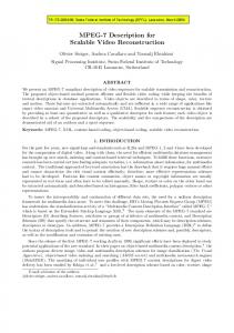
A. Previous Work & Background The main building block of the proposed parallel sorting architecture is rank-ordering based sorter block [1] [2], for which, a bit-serial algorithm was chosen as the basis [3]. The overall architecture of the sorting engine is shown in Figure 1. The flow of data through the modular sorter core is being regulated by complementary input and output shift register arrays, which are used to stagger indidivual bit-planes of each input vector to enable bit-level pipelined operation. The control logic is responsible for regulating the data circulation path, and for applying the rank selection signals to the individual bitplanes, in ascending or descending order. The fact that each individual bit-plane is capable of processing a different rank at any given time significantly increases the overall efficiency of this architecture. In a typical sorting run, the control logic simply requests each bit-plane to process a different rank in each clock cycle, either beginning from the maximum rank and descending, or beginning from the minimum rank and ascend-
ing. It was demonstrated that this sorting engine is capable of producing a fully-sorted output vector set in any rank order in (m+n-1) clock cycles, i.e., in linear time, where, ’m’ is the number of vectors to be sorted and ’n’ is the bit-length, the number of bits used to represent each input vector.
Control signals
CONTROL BLOCK
from the user
Control feedback to the user used to convert bit−wise
used to obtain
staggered output vectors
bit−wise staggered
DataMUX
Rank control bus
data vectors.
control bus
to the majority gates
back to normal.
Sorter slice − MSB
INPUT
Sorter slice − MSB2
OUTPUT
sorter data
SHIFT
SHIFT
sorter data
input bus
REGISTER
REGISTER
output bus
ARRAY
ARRAY
Sorter slice − MSB3
Sorter slice − LSB
SORTER CORE
Fig. 1. Top-level blocks in the sorter architecture. This block is one of the main building blocks of the proposed parallel sorting architecture.
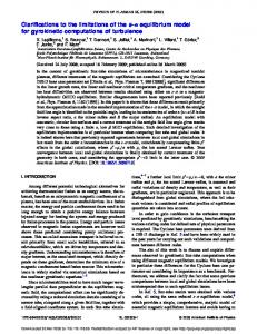
The bit-serial operation of the algorithm suggests a simple bit-level pipelined data architecture, consisting of data modifier-propagator block (ROF cells) to handle fine-grained data selection, and the majority decision blocks (majority function) to determine the output bits. The modular two dimensional array architecture consisting of these two major blocks enables fully scalable construction of structures of arbitrary window size and bit-length. The bit-lenght dictates the number of majority decision gates (rows or slices), whereas the window size determines the number of ROF cells driving one of these majority gates in one slice (columns). The structure of one row is shown in Figure 2. The programmable majority function is the key operation that must be performed in each row. This function also determines the overall operation speed (i.e., the clock frequency), since the m-input majority function must be performed in each clock cycle. The majority gate has been realized with fully combinational parallel counter, which consists of full adders connected in a tree network and an output comparator. A sorting engine based on the architecture described above for processing 127 input vectors of 16-bits has been realized using conventional 0.35µm technology. The architecture consists of 16 rows, where each row is capable of processing 127 bits simultaneously. This 127x16 sorting engine is the main building block of the proposed larger parallel-sorting architecture.
Select signal from the control block
MUX
Rank bus from the control block
Propagating data from the bit-slice Output of the majority gate (fed back to the ROF Cells)
Actual Data output of the last ROF Cell
A Y B
Shifted data from the input shift registers
S
Shifted data to the bit-slice
ROF CELL
ROF CELL
Actual input data flow through the ROF Cells
DFF
D Q
RANK REG
ROF CELL MAJORITY
Input bus to the Select signal for the next lower bit-slice
majority gate
GATE Rank for the next lower bit-slice
Bit-slice output to the output shift register
Fig. 2. The block-level structure and the signal flow in one sorter bit-slice.
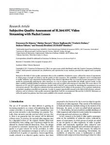
B. Neighborhood-Sort Algorithm To be able to process larger numbers of input vectors, there is a need for an algorithm, which would make smaller sorter blocks run in parallel and provide that a large number of input vectors are sorted either in ascending or in descending order. Among different parallel sorting algorithms, the neighborhood sort algorithm is chosen for its simplicity and its applicability in the forementioned sorting architecture [4]. Figure 3 shows an example for how the algorithm works. In this example, the goal is to sort 12 integers (from 1 to 12), which are given in a random order, using three sorting blocks, each of which, is capable of sorting up to four numbers in one step. The algorithm is mainly a loop of individual sorting of the data in each sorter block, transferring the highest “k” numbers (k =2 in the given example) to the neighboring block (the block at the right), do individual sorting again with the new block contents and then providing the “k” smallest numbers to the neighbor at the opposite side (the block at the left side), until the sorting is completed. This loop dictates that there has to be a check step after every individual sorting of each block contents to see if the numbers are already in the desired order (min-to-max in the example). In the example, each sorter first sorts its contents and then transfer the two largest numbers to the neighboring sorter block (at the right side). The right-most block stores its two largest numbers for a later step, which are not taken into account just for this one step; and it gets another two numbers from the neighboring block to its left. After the next sort operation, this time each sorter block sends its two smallest number to its neighbor at its left. Also, the two numbers stored by the right-most block are shifted inside that block and the sorting is repeated again for each sorter block. This operation goes on until all the numbers are sorted in the increasing order starting from left going to right. As one can easily observe from Figure 3, to sort eight numbers in increasing order with three individual sorter blocks, took four sorting and four shifting operations.
Fig. 3. The operation of the neighborhood-sort algorithm.
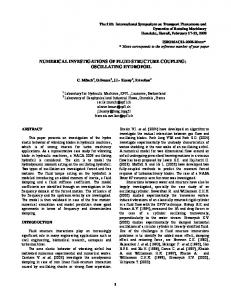
Fig. 4. The implementation of the slightly-changed neighborhood-sort algorithm as part of the proposed sorting architecture.
The proposed architecture employs a slightly changed version of this algorithm, where, “k” possible smallest numbers (“0 0”) are fed from the left side (where we assume that the sorter block processing the minimum numbers is located) and “k” highest possible numbers (represented with “F F”) are provided from the right side (at which, we assume the sorter block that at the end of the process will store the highest numbers, is located), as seen in Figure 4. Whenever Sorter1 needs to transfer data from Sorter2, its two ’0’s are thrown away, later when the data is shifted right, Sorter1 recovers the zeros back. This change in the algorithm makes all the sorting blocks act the same way independent of their location and therefore eases the the job of the control logic. III.
S YSTEM A RCHITECTURE
The modified neighborhood-sort algorithm dictates the need for two main operations: • Transfer of data from one sorter block to other. • Sorting of the content of each sorter block. The previous section presented a sorter block, which can handle up to 127 16-bit input vectors. This block is used for implementing each ’Sorter’ cell of the table shown in Figure 4. Hence, each cell of the table corresponds to a sorter module of 127 input vectors at the implementation side. The other main operation listed above, the transfer of data among blocks, requires a data storage structure and a dedicated control system to ensure the transferred data is received by the correct sorter module. The implementation of the data transfer is illustrated in Figure 5. It is shown that the sorter block receives half of its input vectors from one of its neighboring blocks, either from the left one or from the right depending on the type of data being transferred, and the other half consists of the vectors which were sorted during the previous step by the block itself. At the same time, each sorter module sends corre-
Communication Control output Control inputs
SORTER CONTROL
COMMUNICATION CONTROLLER
Data from left Data from right
REGISTER FILE
ISRA
Data to neighbors
SORTER CORE
Own data
OSRA
Data Selection Multiplexers
Fig. 5. Implementation of the data transfer among neighboring sorter blocks. ISRA and OSRA stand for Input and Output Shift Register Array, respectively.
sponding half of its sorted content to its neighbors, which will be accepted only by the appropriate sorter module. Assuming desired sorting order is from minimum to maximum, i.e., the maximum vector appears first at the output of every sorter module, the corresponding data flow is given below in Table I, including the number of clock cycles required for each operation. It should be noted that the net effect of such a scheme is to push the larger vectors to the rightmost sorter modules and the smaller vectors to the leftmost sorter modules, until the sorting operation is accomplished globally, which is checked by the “Global check” routine. It can be seen that the system operates in units of 143 clock cycles, which is determined by the total number of registers that a input vector must be shifted through; 127 for storing the results of the sorting operation, plus, 16 to hold them inside the corresponding block during the global check. One complete round takes 4 × 143 = 572 clock cycles, after which, another round starts. The so-called “global check” step is used to check if at any moment all the vectors are sorted in the desired order. Under the assumption that a sorting system has ’n’ sorter modules, the condition to confirm the finish of the global sorting operation is the synchronous correctness of all the local conditions below: min (Sorter #1) > max (Sorter #2) min (Sorter #2) > max (Sorter #3) ······ min (Sorter #(n − 1)) > max (Sorter #n) IV.
H ARDWARE R EALIZATION
The generic 127 x 16-bit sorter core has been synthesized, and mapped on a 0.35 um CMOS standard cell library including the register blocks, and the control-communication circuits. The structure consists of 16 individual rows (see Figure 1), each corresponding to one bit-slice. Each row contains 127 ROF cells that are responsible for the low-level implementation of the bit-serial sorting algorithm. The critical path was identified as the 127-bit majority decision circuit that needs to operate for each bit slice concurrently. It was found that the worst case input to output delay of this 127-bit majority decision block can
TABLE I
R EGULAR OPERATION OF THE SYSTEM . N OTE THAT THE VALUES FOR CLOCK CYCLES ARE VALID ONLY FOR THE CASE , WHERE THE SYSTEM EMPLOYS SORTER MODULES OF
# of clock cycles 0-63 64-127 127-143 143-286 286-349 349-413 413-429 429-572
127
VECTORS .
Operation in registers Shift in data from left Shift in own data Shift data& Global check null Shift in own data Shift in data from right Shift data& Global check null
Operation in sorters Produce the maximum half Produce the minimum half Start filling ISRA Shift data inside core Produce max half Produce the minimum half Start filling ISRA Shift data inside core
be optimized by using the procedural description of the majority function. This results in a worst case delay of approximately10 ns for the majority block, allowing a clock frequency of 100 MHz for the overall system. The standard cell realization of one sorter core block is shown in Figure 6 after placement and routing using Silicon Ensemble. The dimensions of the block are 845µm x 820µm, including the register files and the local control unit. Once the basic building block of the system is generated, a much largercapacity parallel sorting engine can be constructed by linking a number of such units in cascade configuration, as depicted in Figure 7 for 16 individual units. The key point is that the capacity of the system can be arbitrarily increased by simply attaching additional units, limited only by the clock distribution network and the data transmission speed between the modules. To achieve a cost-effective solution, it was decided to place 4 individual sorter units on each chip, which results is a relatively small chip size (using 0.35 um CMOS technology) of approximately 25mm2 including the I/O pads. To reduce the cost even
ACKNOWLEDGMENT The authors thank Ms. Tu˜gba Demirci of Cypress Semiconductors Istanbul Design Center, for her invaluable contributions in the early stages of this research. R EFERENCES ˙ Hatırnaz, Y. Leblebici, “Scalable Binary Sorting Architecture Based on [1] I. Rank-Ordering”, Proceedings of ISPACS 2000, Hawaii, October 2000. [2] T. Demirci, ˙I. Hatırnaz, Y. Leblebici, “CMOS Realization of a Scalable High-Performance Binary Sorting Engine Suitable for Embedded Applications”, ASIC/SOC 2000, Rochester, NY, September 2002. [3] B.K. Kar, D.K. Pradhan, “ A New Algorithm for Order Statistic and Sorting”, IEEE Trans. on Signal Proc., vol. 41, pp 2688-2694, August 1993. [4] A. Park and K. Balasubramanian, “Improved Sorting Algorithms for Parallel Computers,” Proceedings of 15th Annual Conference on Computer Science, 1987, pp. 239-244. [5] W.K. Lam and C.K. Li, “Binary sorter by majority gate,” IEE Electronic Letters, Vol. 32, July 1996. [6] C.C. Lin, C.J. Kuo, “Fast response 2-D rank order algorithm by using max-min sorting network,” International Conference on Image Processing 1996, Vol. 1, pp. 403-406. Fig. 6. Standard-cell layout view of the 127x16 sorting engine.
Fig. 7. The top-level placement of the sorter modules and the direction of the data path.
more, only a single layer of conductor is used in MCM and much effort is spent on ensuring that there isn’t any overlapping paths. Utilizing 16 such chips in a cascade configuration produces an aggregate sorting capacity of 8k x 16-bit (= 128 kbits). This capability is significantly higher than those of previously reported sorting arrangements [5], [6]. The control circuitry of the sorter is designed in a way, which makes it possible to send data to the MCM sorter and to receive data from it. This communication can be realized by connecting the sorter to a serial port and writing an assembly code to take care of the communication. V.
C ONCLUSIONS
A multi-chip implementation of parallel sorting engine is presented. The proposed architecture is based on parallel processing of a large number input vectors by a number of individual sorting engines, which exchange data after finishing the local sorting operation. The design given in this paper has a capacity of sorting 8k input vectors, each of which is 16 bits.