MATEC Web of Conferences 139, 00174 (2017) ICMITE 2017
DOI: 10.1051/matecconf/201713900174
Modeling and Predicting Cross-sectional Surface Roughness for the Grinding Process Qiang Li 1,a, Peilian Tan 1,b *
1
School of Mechanical Engineering, Hunan Industry Polytechnic, Changsha 410082, China Abstract. This paper proposes a new algorithm for predicting the cross-sectionalsurface roughnesst of the workpiece for the grinding process, which reduces three-dimensional modeling to two-dimensional modeling by virtue of the cross-sectional area of the undeformed grinding chip. Besides, this paper develops a search technique to figure out systematically the surface roughness in order to determine the final cross-sectional surface roughness produced by thousands of grinding wheel grains with randomly distributed protrusion heights. The simulated results are consistent with the measurement data,which proves the effectiveness of the proposed algorithm.
1 Introduction The face gear transmission performance, vibration, noisy and working life are decided by tooth surface in a great extent. In Engineering, the surface roughness is usually measured perpendicular to the grinding direction. The typical sampling length for the grinding surface roughness measurement is 0.8 mm, and usually the evaluation length should contain 5 consecutive sampling lengths. Current methods, however, aim at threedimensional area simulation which is carried out on a rather small scale [1-5]. Much more time will be consumed if the simulation scale is increased. In this paper, a new algorithm is developed for predicting the cross-sectional surface roughness of the workpiece for the grinding process. It can simulate an arbitrary crosssection of the surface topography, and take into consideration the random distribution of the grain protrusion heights. First, the principle of the simulation technique is introduced by virtue of the cross-sectional area of the undeformed grinding chip to reduce threedimensional modeling to two-dimensional modeling. Then, the interaction of grain with cross section is given and the projection of the undeformed grinding chip on the cross-section is studied. Still, a search algorithm is developed to obtain the final surface roughness. Finally the simulation results are given and verified in part of characteristic in comparison with experimental data.
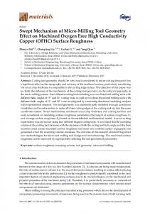
2 Simulation Technique The schematic diagram of surface grinding is shown in coordinate system is set with its Fig.1. A o xyz o origin fixed on the grinding wheel spindle. The crosssection I is any work-section perpendicular to the grinding direction. The abrasive grains in the grinding wheel are represented with polar coordinates ( y , , ). *
In order to simplify the grinding kinematic analysis, the assumptions adopted in the present work for predicting the cross-sectional surface roughness are as follows: 1) the abrasive grains are conical in shape; 2) the distribution of the grain intervals is uniform, and the grain interval L (mm) can be determined as L 137.9 M 1.4 3
[6], where M is the grit number and 32 S
S is the structure number of the wheel; 3) the grain protrusion height h is distributed with mean value and standard deviation . is given by 68 M 1.4 , and can be estimated as (15.2 M 1 68M 1.4 ) / 3 . During the grinding process, the grains on the surface of the wheel pass through the workpiece and cut a portion of the workpiece material. The final topography of cross-section I is the surface shape of the material remaining on the cross section after the passage of all the engaged grains through the cross-section. The generation of the cross-sectional surface is sketched in Fig.2, where the numbers represent the grains in one row. According to the assumptions, the grain protrusion heights are subject to Gaussian distribution, in j row, not all the grains will leave marks on the cross-section and those that do will be the ones trajectory with low intersection with the cross-section. The simulation comprises three steps: (i) the intersecting point of the arbitrarily distributed grains in row with the cross-section is calculated, and j subsequently, the lowest point is calculated in j row; (ii) the grain protrusion height associated with the lowest point is confirmed and the intersection of the two adjacent triangles is calculated; (iii) surface generation is simulated geometrically with reference to the shape of the projection triangle.
Corresponding author:
[email protected]
© The Authors, published by EDP Sciences. This is an open access article distributed under the terms of the Creative Commons Attribution License 4.0 (http://creativecommons.org/licenses/by/4.0/).
MATEC Web of Conferences 139, 00174 (2017) ICMITE 2017
DOI: 10.1051/matecconf/201713900174
The intersecting points of the arbitrarily distributed grains m and n in one row with the cross-section are is shown in Fig.3. In the x z coordinate system, the trajectory of grain m can be expressed as
x x m m sin m z rm cos m
(1)
where xm is the moving distance of the wheel center
when grain m becomes involved in grinding, and it can be expressed as
xm
m is m sin m
Since that
vw
m
small,
(2) it
can
be
approximated
. Substitute it into Eq. (1) and the
equation can be simplified to
Fig.1 Kinematic relation between wheel and workpiece.
x x m m m m2 z ( 1 ) m 2
(3)
Substitute Eq. (2) into Eq. (3) to eliminate parameter m ,
then the equation can be expressed as
z
Fig.2 Schematic of the cross-section generation during grinding.
vw
2 m2 ( x
2 m
m ) 2
(4)
Set x I as the distance between the cross-section I and the origin of the coordinate, and then the intersecting point of grain m with the cross-section I can be expressed as
zm
2 m2 ( x I 2 m
vw
m ) 2
Similarly, the intersecting point of grain cross-section I can be expressed as
zn
2 n2 ( x I 2 n
vw
(5)
n with the
n ) 2
(6)
The smaller value of z m and z n is chosen as the final
intersection which will leave marks on the cross-section. Set ae as the depth of cut and min as the minimum
radius in one row, and then the limit value of the intersection of the grain with the cross-section can be expressed as Fig.3 The intersecting point of the arbitrarily distributed grains
min a e
in one row with the cross-section.
2 (xI 2 min
2 min
vw
)2
(7)
Along each row, number the grains engaged with the cross-section I as 1,2,...i 1, i , and then the grain in j row which will leave marks on the cross-section can be determined as
2.1 Intersecting Point of the Arbitrarily Distributed Grains in one Row with the Crosssection
2
MATEC Web of Conferences 139, 00174 (2017) ICMITE 2017
z ( j ) minz j1 , z j 2 ,..., z j ( i 1) , z ji
DOI: 10.1051/matecconf/201713900174
(8)
z z ( p)
1 [ y ( p 1) L] tan
(12)
1 [ y (q 1) L] tan
(13)
2.2 Prediction of Surface Roughness
z z (q)
The generation of the cross-section during grinding is shown in Fig.4. Set B1 , B2 ,..., B j 1 , B j as the grains associated with the lowest intersection point in each row in the y z plane. The point B1 is the origin in y direction coordinate, and the value in z direction coordinate which can be given according to Eq. (8) can be written as (0, z 1 ). Linear equation of B1 D1 can be expressed as
The intersection G p between these lines can be solved by using Eq. (12) and Eq. (13) as tan ( q ) L ( p) y 2 ( z z ( p q 2) tan ) (14) z 1 ( z ( p ) z ( q ) (q 1) L ) 2 tan The final surface profile of the cross-section is formed by connecting successive points B1 , G1 , B2 , G2 , …, B j and G j , which can be solved by using Eq. (12) to Eq. (14).
3 Simulation The proposed method is applied to simulate the crosssectional surface roughness of the experiment data in [7]. Table 1 lists the grinding and wheel parameters. The surface roughness on the cross section is measured with a cut-off length of 0.8 mm. Since the evaluation length should contain 5 consecutive sampling lengths, the simulation length in the cross-sectional direction is taken as 5 mm. Table 2 shows the roughness results compared with the measurement and references. From table 2, we can see the simulation result is consistent with the experiment data. The main simulation error caused by this method is attributed to the difference between the assumption and the process in the distribution and the shape of the grains. In practice, the grain interval is random and the grain shapes are complex basic geometries, such as ellipsoid, tetrahedron, cuboids and octahedron. In simulation, the undeformed chip cross section is assumed to be triangular in shape. However, the undeformed chip cross section for a dulled flattened pyramidal-shaped grit having a wear flat at its tip of dimension leads to a trapezoidal cross section. For all that, the simulation data proposed in this paper is closer to the experiment data compared with references [8]. Since only one of the cross-sections is simulated in this method, a lot of time is saved and the simulation scale is expanded.
Fig.4 Generation of the cross-section during grinding.
z z (1)
1 y tan
(9)
According to the basic assumption, the uniform grain interval is L , so the coordinate of point B2 can be written 2
as ( L , z ). Linear equation of B2 C2 can be expressed as
z z ( 2)
1 ( y L) tan
(10)
The intersection G1 between these lines can be solved by using Eq. (11) and Eq. (12) as
tan ( 2 ) L (1) y 2 ( z z tan ) z 1 ( z ( 2 ) z (1) L ) 2 tan
(11)
If there is no intersection between line B1 D1 and B2 C2 , it indicates that only one grain which has smaller intersection with the cross-section will leave marks on the final profile. Select the smaller value of z1 and z 2 as point B1 , and then calculate the intersection with the adjacent grains. Similarly, for the arbitrary intersections B p and Bq in
Table 1. Wheel and grinding parameters Nominal wheel diameter (mm) 203
the y z plane, the linear equations of B p D p and Bq Cq can be expressed respectively as
3
Grain mesh size
Structure number
180
8
Wheel spindle speed (rpm) 4500
Table speed (m/s) 0.06
MATEC Web of Conferences 139, 00174 (2017) ICMITE 2017
DOI: 10.1051/matecconf/201713900174
Table 2. Surface roughness compared with the experiment Simulated data(this paper)
Simulated data [7]
Experiment data [8]
2.0
2.73
1.5
Ra (μm)
4 Conclusion (1) A new algorithm for predicting the cross-sectional surface roughness of the workpiece for the grinding process is developed in this paper. It takes into consideration the random distribution of the grain protrusion heights and reduces three-dimensional modeling to two-dimensional modeling by introducing the cross-sectional area of the undeformed grinding chip, which not only saves a lot of time but also expands the simulation scale. (2) The simulation shows that the proposed method gives the results that are consistent with the measurement ones, thus the effectiveness of the algorithm is guaranteed. This research did foundation work for the modeling and predicting surface roughness of the face gear grinding process.
Acknowledgement This Project is supported by Scientific Research Fund of Hunan Provincial Education Department(14B052)
References 1. 2. 3. 4. 5. 6. 7. 8.
Y.Liu, A.Warkentin, R.Bauer, et al: Precis Eng Vol. 37, 758-764(2013). E.Brinksmeier, J.C.Aurich, E.Govekar, et al: Annals of the CIRP Vol. 55,667-696(2006). X.Chen, W.B.Rowe:Int J Mach Tool Manu Vol. 36,871-882,(1996) . X.Chen, W.B.Rowe: Int J Mach Tool Manu Vol. 36,883-896,(1996). P.Koshy, L.K.Ives, S.Jahanmir: Int J Mach Tool Manu Vol.39, 1451-1470,(1999). S.Agarwal, P.Venkateswara Rao: Int J Mach Tool Manu Vol. 50,1065-1076,(2010).. X.Zhou, F.Xi: Int J Mach Tool Manu Vol.42, 969977,(2002). T.W.Hwang., C.J.Evens., S.Malkin:J Manuf Sci ET ASME Vol. 122,42-50 (2000).
4